Use instructions –Hinge safety limit switch ISTR 04 SC 0118-00
The CE declaration of this product is available in the download section of website www.comepi.it or by writing to the following email address:
tecnico@comepi.it
DDC 03 –Safety limit switches series SP-SM-SDP-SDM-SBP-SBM-SCM-SFP
The COMEPI safety limit switches are devices designed and made in compliance
with the international IEC regulations and the EN European standards. They can
be used for monitoring guards on industrial machines and for building safety
systems in compliance with standard EN ISO 14119. Being a protection
equipment for operators, its incorrect installation or tampering can damage
people, even seriously. The device installation must be carried out according to
the regulations in force by authorized staff only. Make sure the switch works
properly before starting the machine and periodically check the correct
operation of the equipment.
Installation precautions
Before starting the machine, check the proper operation of the safety system.
Periodically check the correct operation of the device.
The device installation must be carried out by authorized and qualified staff
only.
The device use must be limited to the applications meeting the regulations
requirements.
The device installation and the safety system design must be carried out only
by people knowing the regulations in force.
The device installation and the safety system design must be carried out in
compliance with the regulations in force.
In case of doubts or special applications, please contact COMEPI Technical
Support.
Before any painting operation, cover the identification label.
Do not install in places where there are flammable dusts or gases.
Do not install in places with strong vibrations; impacts and vibrations can
prevent the switch correct operation.
Only use the installation kit supplied by COMEPI with the device. The use of
different parts does not ensure safety of the device.
During installation follow the procedures described in these instructions and
check the correct operating point according to the opening angle of the guard
and in compliance with the regulations in force.
If the microswitch is damaged or worn, replace the whole device to ensure
safety.
Replace the equipment after exceeding the mechanical durability limit.
During wiring, keep load under the value of the use category.
Check that safety contacts are connected to a protection fuse.
Before reaching the switch contacts, make sure the device is not supplied with
power.
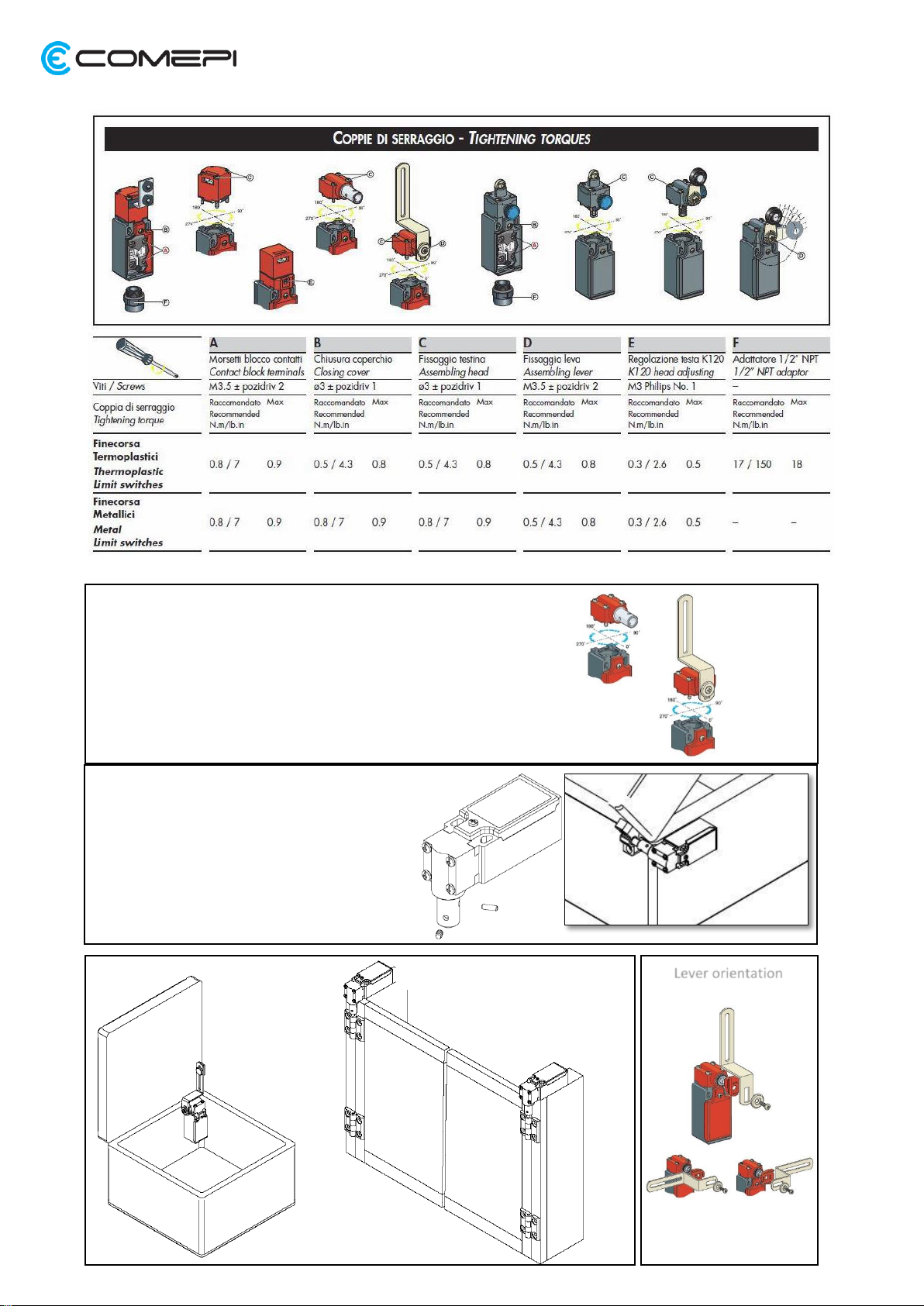
Tighten the screws with the specified tightening torques (0.5Nm plastic, 0.8Nm
metal).
The device must not be disposed of following special procedures, just comply
with the regulations in force in the country where the device is used.
Use limits
Use the switch complying with the regulations in force within its operation
limits and following the instructions. The manufacturer is not to be held
responsible for damages if: the device was not used properly, instructions were
not followed, assembly and maintenance operations were carried out by
unauthorized or unskilled staff, functional tests were omitted.
This device complies with the following Directives:
Low Tension Directive 2014/35/EU
According to standard EN 60947-5-1
Machinery Directive 2006/42/EC
According to standard EN ISO 14119
Directive RoHS 2002/95/EC
Approvals
cULus according to standard UL508 –IMQ according to EN 60947-5-1 (for the
complete list of the certified products, please contact COMEPI Technical
Support).
Use and operation examples
This kind of device is typically used to monitor the safety guards on industrial
machines. When the guard is closed, the microswitch is in the normal operation
condition, while when the guard is open, the signal controlling the machine
stop due to dangerous situation is produced. A single device cannot be used to
ensure safety when the guard protects the perimeter of machines for which
dangerous conditions may last a certain time after generating the stop signal.
Moreover, this device cannot be used as emergency stop device. To test the
proper operation of the equipment, check the correct operation of the
microswitch and close the guard starting the machine. When opening the
guard, the machine stop signal will have to be produced. This signal shall be
produced so as to ensure the operator’s safety and prevent him from entering
the dangerous area during the machine operation. The machine restart must
be impossible while the guard is open and the operator potentially can reach
the dangerous area. The device must not be used as mechanical lock.
Safety warnings
Safety switches protect operators. An incorrect installation as well as the
tampering of the device and of its safety system can cause even extremely
dangerous situations. Never bypass or tamper with the device. In order to avoid
any tampering attempt, it is advisable for the installer to mount the device in a
place that cannot be easily reached by unauthorized staff, even using physical
barriers or other means to make tempering difficult.
Technical data
Technopolymer or painted metal casing
Rated impulsive withstand voltage
Uimp
Room temperature during operation
Conventional thermal current Ith
Environmental designation
Operational current AC-15
Protection against
electrical shocks
Class II (thermoplastic
casing)
Operational current DC-13
Maximum switching frequency
Rated insulation
voltage Ui
500V (400V Z02-X12P-X21P-W03P)
Use categories
according to
UL508
A600 –Q600 (A300-Q300 X12P-X21P-W03P)
Resistance between contacts
Screws M3.5 with cable clamp (M3 for 3 poles
contacts type)
According to IEC 60947-5-1
Dimensions of connecting
cables*
*Only use copper conductors 60/70°C, AWG14-18, stranded and solid conductor. Terminals maximum tightening torque 0.8Nm