Monacor TVSET-450 User manual

Rückfahr-Videosystem
1 Übersicht der Bedienelemente und
Anschlüsse
1Helligkeitsregler
2Kontrastregler
3Umschalter BRIGHT für die Bildhelligkeit am Tag
oder in der Nacht
4Betriebsartenschalter MODE
Taste gedrückt: automatisches Einschalten des
Monitors beim Einlegen des Rück-
wärtsgangs
nicht gedrückt: Dauerbetrieb
5Taste POWER zum Ein- und Ausschalten
6Montagebügel
7Regler V-HOLD für die Bildsynchronisation
8Anschluss POWER für die Betriebsspannung
9Buchse CAMERA zum Anschluss der Kamera
2 Hinweise für den sicheren Gebrauch
Die Geräte (Monitor und Kamera) entsprechen der
Richtlinie für elektromagnetische Verträglichkeit
89/336/EWG.
●Vorsicht! Die Bildröhre des Monitors ist luftleer. Bei
mechanischer Beschädigung besteht Implosionsge-
fahr und Verletzungsgefahr durch herumfliegende
Glassplitter.
●Der Monitor ist nur zur Verwendung im Innenbereich
geeignet.SchützenSieihn vorFeuchtigkeit undHitze
(zulässiger Einsatztemperaturbereich 0–40°C).
●Die Kamera ist spritzwassergeschützt, jedoch nicht
absolut wasserdicht. Tauchen Sie darum die Kame-
ra nicht in Wasser ein.
●Die im Monitor entstehende Wärme muss durch
Luftzirkulation abgegeben werden. Decken Sie
darum die Lüftungsöffnungen am Gehäuse nicht ab.
Stecken Sie nichts durch die Lüftungsöffnungen
bzw. lassen Sie nichts hineinfallen! Dabei kann es
zu einem elektrischen Schlag kommen.
●Verwenden Sie für die Reinigung des Monitors nur
ein trockenes, weiches Tuch, auf keinen Fall Was-
ser oder Chemikalien. Reinigen Sie das Kamera-
gehäuse nicht mit scharfen Reinigungsmitteln oder
Chemikalien.
●Werden die Geräte zweckentfremdet, falsch be-
dient, nicht fachgerecht installiert oder repariert,
kann für eventuelle Schäden keine Haftung über-
nommen werden.
●Sollen die Geräte endgültig aus dem Betrieb
genommen werden, übergeben Sie sie zur Entsor-
gung einem örtlichen Recyclingbetrieb.
3 Einsatzmöglichkeiten
Dieses Videosystem für schwarzweiße Bilddarstellung
ist speziell für die Installation in Kraftfahrzeuge aller
Art konzipiert und ermöglicht eine optimale Rücksicht
z.B. beim Einparken. Es besteht aus einem Monitor,
einer Kamera sowieAnschluss- und Montagematerial.
Der Monitor stellt das Kamerabild spiegelverkehrt
dar, so dass die Sicht wie in einem Rückspiegel er-
scheint. Die Kamera ist spritzwassergeschützt (IP44)
und lässt sich z.B. in die Stoßstange einbauen.
Der Monitor arbeitet mit lebensgefährlich hoher
Spannung. Nehmen Sie deshalb niemals selbst Ein-
griffe im Monitor vor! Durch unsachgemäßes Vorge-
hen besteht die Gefahr eines elektrischen Schlages.
Außerdem erlischt beim Öffnen von Monitor oder
Kamera jeglicher Garantieanspruch.
4 Montage
4.1 Monitor
●Der Monitor muss über den beiliegenden Montage-
bügel (6) fest und fachgerecht an einer mechanisch
stabilenStelle imAuto montiertwerden, damit ersich
nicht löst und zu einem gefährlichen Geschoss wird.
1) Den Montagebügel (6) an geeigneter Stelle fest-
schrauben.
2) Den Monitor nach Abb. 3 an den Montagebügel
festschrauben.
3) BeiBedarf denBlendschutz aufdenMonitor stecken.
Montage Monitor ➂
4.2 Kamera
Um die optimale Kameraposition zu ermitteln, sollte
vor der Montage ein Probebetrieb erfolgen.
1) Ein Loch von 26mm Durchmesser für die Kamera
an die entsprechende Stelle des Fahrzeugblechs
(b) bohren.
Montage Kamera ➃
2) Mit Hilfe eines der abgeschrägten Ringpaare (a)
eine waagerechte oder geneigte Kameraausrich-
tung herstellen. Zum Lieferumfang gehören 3 Ring-
paare für verschiedene Winkel und ein Distanzring.
3) Die Kamera so drehen, dass das Anschlusskabel
nach unten zeigt und das Bild auf dem Monitor
waagerecht dargestellt wird. Die Kamera mit den
beiden Rändelmuttern (c) festschrauben.
abc
®
TVSET-450
BRIGHT MODE POWER
AUTO MANU
4.3 Anschluss
●Die Anschlusskabel so verlegen, daß deren Isolie-
rung nicht beschädigt werden kann.
1) Die Kamera über das beiliegende Verlängerungs-
kabel (20m) an die Buchse CAMERA(9) des Moni-
tors anschließen.
2) Das beiliegende Stromversorgungskabel in die
Buchse POWER (8) des Monitors stecken.
3) Das Stromversorgungskabel mit der KFZ-Bord-
spannung verbinden:
blau: 12V oder 24V über eine entspre-
chende Sicherung
orange: an die Leitung für die Rückfahrschein-
werfer (zum automatischen Einschalten)
schwarz: Masse oder Minuspol der Batterie
5 Bedienung
1) Mit dem Schalter POWER (5) das Videosystem
einschalten.
2) Mit dem Schalter MODE (4) die Betriebsart wählen:
Taste gedrückt: der Monitor wird beim Einlegen
des Rückwärtsgangs automatisch
eingeschaltet
nicht gedrückt: Dauerbetrieb
3) Mit der Taste BRIGHT (3) die Bildhelligkeit wählen:
Taste gedrückt: helles Bild für tagsüber
nicht gedrückt: dunkleres Bild für nachts
4) Bei Bedarf die Helligkeit und den Kontrast mit den
Reglern (1) und (2) optimieren.
5) Wenn das Bild durchlaufen
(Abb. 5) oder flimmern sollte, mit
dem Regler V-HOLD (7) ein sta-
biles Bild einstellen.
Bild läuft durch ➄
6 Technische Daten
Bildschirmdiagonale: . . . 11,4cm (4,5")
Auflösung: . . . . . . . . . . . 380 Linien
Videopegel: . . . . . . . . . . 1Vss/75Ω
Objektiv: . . . . . . . . . . . . . 1:3/2,5mm (130°)
Automatischerelektro-
nischer Verschluss: . . . . 1/50 –1/100000 s
Mindestbeleuchtung: . . . 1 Lux
Stromversorgung:. . . . . . 12V oder 24V /1,2A
Einsatztemperatur:. . . . . 0–40°C
Abmessungen, Gewicht
Monitor: . . . . . . . . . . . 137x126x163mm, 1,1kg
Kamera: . . . . . . . . . . . Ø 25mm x 53mm, 50g
Laut Angaben des Herstellers.
Änderungen vorbehalten.
MONITOR
MONITOR
®
TVSET-450 Best.-Nr. 19.6990
Copyright©by MONACOR®International GmbH & Co. KG, Bremen, Germany. All rights reserved. 08.01.01
®
®
TVSET-450
BRIGHT MODE POWER
AUTO MANU
12 3 4 5 6 7 8 9
V-HOLD POWER CAMERA
nicht angeschlossen
Spannung zum
automatischen Einschalten
Masse+12 V/+24 V
+12 V für die Kamera
Masse
nicht angeschlossen
Masse
Videoeingang
➀➁
®
D A CH

Car Reversing Video System
1 Operating Elements and Connections
1Brightness control
2Contrast control
3Selector switch BRIGHT for picture brightness
during the day or at night
4Selector switch MODE
button pressed: the monitor is automatically
switched on when the car is put
into reverse
not pressed: continuous operation
5POWER switch
6Mounting bracket
7Control V-HOLD for vertical synchronization
8Connection POWER for the operating voltage
9Jack CAMERA for connecting the camera
2 Safety Notes
Theunits (monitorand camera)correspondto thedirec-
tive for electromagnetic compatibility 89/336/EEC.
●Caution! The picture tube of the monitor is vacuous.
Incase of mechanical damage,there is animplosion
hazard and scattered glass may cause injuries.
●The monitor is suitable for indoor use only. Protect it
against humidity and heat (admissible ambient tem-
perature range 0–40°C).
●The camera is splashproof, however, it is not com-
pletely watertight. Therefore, do not immerse the
camera in water.
●The heat generated within the monitor must be car-
ried off by air circulation.Therefore, do not cover the
air vents of the housing with any objects. Do not in-
sert or drop anything through the air vents! This may
result in an electric shock.
●For cleaning the monitor only use a dry, soft cloth, by
no means chemicals or water. For cleaning the
camera housing, do not use strong detergents or
chemicals.
●If the units are used for other purposes than orig-
inally intended, if they are not correctly installed or
operated or not repaired in an expert way, no liabili-
ty for any damage will be accepted.
●If the units are to be put out of operation definitively,
take them to a local recycling plant for disposal.
3 Applications
This video system for black-and-white picture display
has been specially designed for installation in all kinds
of motor vehicles. It allows an optimum rear view, e.g.
when reversing the car into a parking space. The
system consists of a monitor, a camera, and material
for connection and mounting.
The monitor displays the picture of the camera in a
mirror-inverted way so that it seems as if you are look-
ing into a rear view mirror. The camera is splashproof
(IP44) and can be installed e.g. into the bumper.
4 Mounting
4.1 Monitor
●By means of the supplied mounting bracket (6), the
monitor must be mounted rigidly and expertly at a
mechanically stable location in the car in order to
prevent it from getting loose and turning into a dan-
gerous projectile.
1) Fasten the mounting bracket (6) with screws at a
suitable location.
The monitor is supplied with hazardous voltage.
Leave servicing to skilled personnel only! Inexpert
handling may cause an electric shock hazard. Fur-
thermore, any guarantee claim will expire if the moni-
tor or the camera has been opened.
2) Screw the monitor to the mounting bracket accord-
ing to fig. 3.
3) Place the glare shield on the monitor, if required.
Mounting of the monitor ➂
4.2 Camera
To determine the optimum camera position, a test run
should be made prior to mounting.
1) Drill a hole of Ø 26mm for the camera at the corre-
sponding location in the car body sheet (b).
Mounting of the camera ➃
2) Use one of the pairs of bevelled rings (a) to adjust
the camera to a horizontal or inclined position.
Three pairs of rings for different angles and a
distance ring are supplied with the system.
3) Turn the camera in such a way that the connection
cable points downwards and the picture on the
monitor is displayed horizontally. Screw down the
camera with the two knurled nuts (c).
4.3 Connection
●Lay the connection cables in such a way that their
insulation cannot be damaged.
1) Connect the camera to the jack CAMERA (9) of the
monitor via the supplied extension lead (20m).
2) Connect the supplied power lead to the jack
POWER (8) of the monitor.
abc
®
TVSET-450
BRIGHT MODE POWER
AUTO MANU
3) Connect the power lead to the electrical system of
the car:
blue: 12V or24V via a corresponding fuse
orange: to the line for the reversing lights (for
automatic start)
black: ground or negative pole of the battery
5 Operation
1) Switch on the video system with the POWER
switch (5).
2) Select the operating mode with the switch MODE (4):
button pressed: the monitor is automatically
switched on when the car is put
into reverse
not pressed: continuous operation
3) Select the picture brightness with the button
BRIGHT (3):
button pressed: bright picture during the day
not pressed: darker picture at night
4) Use the controls (1) and (2) to optimize brightness
and contrast, if required.
5) If the picture rolls up or down
(fig.5) or if it flickers, adjust a
stable picture with the control
V-HOLD (7).
Picture rolls up or down ➄
6 Specifications
Diagonal screen size:. . . 11.4cm (4,5")
Resolution: . . . . . . . . . . . 380lines
Video level:. . . . . . . . . . . 1Vpp/75Ω
Lens:. . . . . . . . . . . . . . . . 1:3/2.5mm (130°)
Automatic electronic
shutter: . . . . . . . . . . . . . . 1/50 –1/100000 s
Minimum illumination:. . . 1lux
Power supply:. . . . . . . . . 12V oder 24V /1.2A
Ambient temperature:. . . 0–40°C
Dimensions, weight
Monitor: . . . . . . . . . . . 137x126x163mm,1.1kg
Camera: . . . . . . . . . . . Ø 25mm x 53mm, 50g
According to the manufacturer.
Subject to technical change.
®
TVSET-450 Best.-Nr. 19.6990
Copyright©by MONACOR®International GmbH & Co. KG, Bremen, Germany. All rights reserved. 08.01.01
®
®
TVSET-450
BRIGHT MODE POWER
AUTO MANU
12 3 4 5 6 7 8 9
V-HOLD POWER CAMERA
not connected voltage for automatic start
ground+12 V/+24 V
+12 V for the camera
ground
not connected
ground
video input
➀➁
®
MONITOR
MONITOR
GB

Système vidéo pour
marche arrière
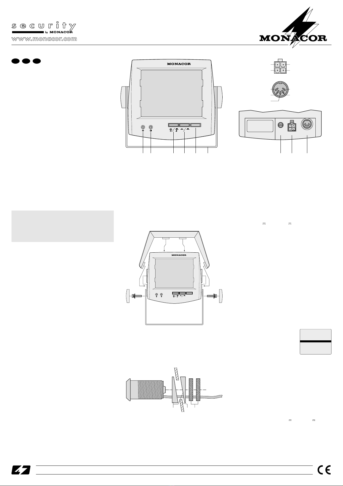
1 Eléments et branchements
1Potentiomètre de réglage de la luminosité
2Potentiomètre de réglage du contraste
3Commutateur BRIGHT pour la luminosité de
l’image le jour ou la nuit
4Sélecteur du mode de fonctionnement MODE:
touche enfoncée:
allumage automatique du moniteur lorsque la
marche arrière est engagée
touche non enfoncée:
fonctionnement en continu
5Touche POWER interrupteur marche/arrêt
6Etrier de montage
7Potentiomètre de réglage V-HOLD pour la syn-
chronisation d’images
8Prise POWER pour la tension de fonctionnement
9Prise CAMERA pour brancher la caméra
2 Conseils d’utilisation
Les appareils (moniteur et caméra) répondent à la
norme européenne relative à la compatibilité électro-
magnétique 89/336/CEE.
●Attention: Le tube du moniteur est vide d’air; en cas
de dommage mécanique, le risque d’implosion
existe pouvant engendrer des blessures par les
éclats de verre.
●Le moniteur n’est conçu que pour une utilisation en
intérieur, protégez-le de l’humidité et de la chaleur
(température d’utilisation 0–40°C).
●La caméra est protégée contre les projections d’eau
mais pas absolument étanche; ne la plongez jamais
dans l’eau.
●La chaleur dégagée par le moniteur doit être éva-
cuée par une circulation d’air suffisante. En aucun
cas,les ouïes deventilation duboîtier ne doiventêtre
obturées par quelque objet que ce soit. N’introduisez
rien ou ne faites rien tomber dans les ouïes de ven-
tilation; vous pourriez subir un choc électrique.
●Pour nettoyer le moniteur, utilisez un chiffon sec et
doux, en aucun cas, de produits chimiques ou
d’eau. Pour nettoyer le boîtier de la caméra, n’utili-
sez pas de détergents ou de produits chimiques.
●Nous déclinons toute responsabilité en cas de dom-
mage si les appareils sont utilisés dans un but autre
que celui pour lequel ils ont été conçus, s’ils ne sont
pas correctement réparés, installés, ou utilisés.
●Lorsque les appareils sont définitivement retirés du
service, vous devez les déposer dans une usine de
recyclage adaptée.
3 Possibilités d’utilisation
Ce système vidéo avec visualisation en noir et blanc
est conçu pour être installé dans des véhicules de tout
type et permet d’effectuer une marche arrière optima-
le, par exemple pour se garer en marche arrière. Il se
compose d’un moniteur, d’une caméra et des acces-
soires de montage et de branchement.
Le moniteur affiche l’image de la caméra en mode
miroir, l’image apparaît comme dans un rétroviseur. La
caméra est protégée contre les projections d’eau (IP44)
et peut être installée, par exemple dans le pare-chocs.
4 Montage
4.1 Moniteur
●Le moniteur doit être fixé à l’aide de l’étrier de mon-
tage (6) livré et placé dans le véhicule à un endroit
Le moniteur est alimenté par une tension très dange-
reuse. Ne touchez jamais l’intérieur du moniteur car
encas de mauvaise manipulation,vous pourriez subir
un choc électrique. En outre, l’ouverture du moniteur
ou de la caméra rend tout droit à la garantie caduque.
mécaniquement stable pour éviter qu’il ne se dévis-
se et devient un projectile dangereux.
1) Vissez l’étrier (6) à l’endroit approprié.
2) Vissez ensuite le moniteur sur l’étrier comme indi-
qué sur le schéma 3.
3) Si besoin, vous pouvez placer sur le moniteur la
protection contre l’éblouissement.
montage moniteur ➂
4.2 Caméra
Pour déterminer la position optimale de la caméra,
nous vous conseillons d’effectuer une marche d’essai
avant de la placer définitivement.
1) Percez, pour la caméra, un trou de diamètre
26mm, à l’endroit voulu (b) dans la tôle du véhicu-
le.
montage caméra ➃
2) A l’aide d’une des paires d’anneaux en biais (a),
créez une orientation horizontale ou penchée de la
caméra. 3 paires d’anneaux pour divers angles et
un anneau de distance sont livrées.
3) Tournez la caméra de telle sorte que le câble de
connexion soit dirigé vers le bas et que l’image sur
le moniteur soit horizontale. Vissez ensuite la
caméra avec les deux écrous moletés (c).
4.3 Branchement
●Placez les câbles de branchement de telle sorte
que l’isolation ne soit en aucun cas endommagée.
abc
®
TVSET-450
BRIGHT MODE POWER
AUTO MANU
1) Reliez la caméra via le cordon prolongateur (20m)
à la prise CAMERA (9) du moniteur.
2) Reliez le cordon d’alimentation livré à la prise
POWER (8) du moniteur.
3) Reliez le cordon d’alimentation à la tension d’ali-
mentation du véhicule:
bleu: 12V ou 24V via un fusible corres-
pondant
orange: au branchement pour les feux de marche
arrière (pour allumage automatique)
noir: masse ou pôle moins de la batterie
5 Fonctionnement
1) Allumez le système vidéo avec l’interrupteur
POWER (5).
2) Avec le sélecteur MODE (4) sélectionnez le mode
de fonctionnement:
touche enfoncée:
allumage automatique du moniteur lorsque la
marche arrière est engagée
touche non enfoncée:
fonctionnement en continu
3) Avec la touche BRIGHT (3), réglez la luminosité de
l’image
touche enfoncée:
image claire pour le jour
touche non enfoncée:
image plus sombre pour la nuit
4) Si besoin, utilisez les potentiomètres (1) et (2) pour
régler le contraste et la luminosité.
5) En cas de mouvement continu de
l’image (schéma 5) ou de scin-
tillement, stabilisez l’image avec
le réglage V-HOLD (7).
mouvement continu de l’image ➄
6 Caractéristiques techniques
Diagonale écran: . . . . . . 11,4cm (4,5")
Résolution: . . . . . . . . . . . 380lignes
Niveau vidéo: . . . . . . . . . 1 Vcc/75Ω
Objectif: . . . . . . . . . . . . . 1:3/2,5mm (130°)
Obturation électronique
automatique:. . . . . . . . . . 1/50 –1/100000 s
Luminosité minimale: . . . 1lux
Alimentation:. . . . . . . . . . 12V oder 24V /1,2A
Température d’utilisation: 0–40°C
Dimensions, poids
Moniteur: . . . . . . . . . . 137x126x163mm, 1,1kg
Caméra: . . . . . . . . . . . Ø 25mm x 53mm, 50g
D’après les données du constructeur.
Tout droit de modification réservé.
®
TVSET-450 Best.-Nr. 19.6990
Copyright©by MONACOR®International GmbH & Co. KG, Bremen, Germany. All rights reserved. 08.01.01
®
®
TVSET-450
BRIGHT MODE POWER
AUTO MANU
12 3 4 5 6 7 8 9
V-HOLD POWER CAMERA
non branché
tension pour
allumage automatique
masse+12 V/+24 V
+12 V pour la caméra
masse
non branché
masse
entrée vidéo
➀➁
®
F B CH
MONITOR
MONITOR

Sistema di controllo video
dalla retromarcia
1 Elementi di comando e collegamenti
1Regolatore luminosità
2Regolatore contrasto
3Commutatore BRIGHT per la luminosità dello
schermo di giorno e di notte
4Selettore MODE della modalità di funzionamento
tasto premuto attivazione automatica del monitor
quando si innesta la retromarcia
non premuto funzionamento permanente
5Interruttore POWER per accendere/spegnere
6Staffa di montaggio
7Regolatore V-HOLD per la sincronizzazione dell’
immagine
8Connessione POWER per la tensione d’esercizio
9Presa CAMERA per il collegamento della teleca-
mera
2 Avvertenze di sicurezza
Gli apparecchi (monitor e telecamera) corrispondono
alla direttiva CE 89/336/CEE sulla compatibilità
elettromagnetica.
●Attenzione! Il tubo catodico del monitor è a vuoto.
Nel caso di danno meccanico esiste il pericolo di
implosione e la possibilità di danni alle persone per
schegge volanti.
●Il monitor è previsto solo per l’uso all’interno. Pro-
teggerlo dall’umidità e dal calore (temperatura d’im-
piego ammessa fra 0–40°C.).
●La telecamera è protetta contro gli spruzzi d’acqua,
ma non è a tenuta d’acqua. Non immergerla nell’ac-
qua.
●Deve essere garantita la libera circolazione dell’aria
per dissipare il calore che viene prodotto all’interno
del monitor. Non coprire in nessun modo le fessure
di aerazione. Non inserire oggetti nelle fessure di
aerazione e non farci cadere niente. Altrimenti si
potrebbe provocare una scarica elettrica.
●Per la pulizia usare solo un panno morbido, asciut-
to; non impiegare in nessun caso prodotti chimici o
acqua. Non pulire il contenitore della telecamera
con detersivi o prodotti chimici aggressivi.
●Nel caso d’uso improprio, di collegamenti sbagliati,
d’impiego scorretto o di riparazione scorretta non si
assume nessuna responsabilità per eventuali danni.
●Se si desidera eliminare gli apparecchi definitiva-
mente, consegnarli per lo smaltimento ad un’istitu-
zione locale per il riciclaggio.
3 Possibilità d’impiego
Questo sistema video in b/n è stato realizzato per l’in-
stallazione in autoveicoli di ogni genere, e offre una
vista ottimale sul lato posteriore del veicolo, p.es.
durante il parcheggio. È composto da un monitor, da
una telecamera e dal materiale di collegamento e di
montaggio.
Il monitor fornisce un’immagine specchiata: la vista
è quindi come in un specchietto retrovisore. La teleca-
meraè protetta contro glispruzzi d’acqua (IP44)e può
essere montata p.es. nel paraurti.
Il monitor funziona con tensione pericolosa. Non
intervenire mai al suo interno; la manipolazione scor-
retta può provocare delle scariche pericolose. Nel
caso di apertura del monitor cessa ogni diritto di
garanzia.
4 Montaggio e collocazione
4.1 Monitor
●Il monitor deve essere fissato bene e a regola d’ar-
te in un punto meccanicamente robusto del veicolo
servendosi della staffa (6) in dotazione, per esclu-
dere che si possa staccare diventando un proiettile
pericoloso.
1) Avvitare bene la staffa di montaggio (6) in un punto
adatto.
2) Avvitare il monitor sulla staffa come da fig. 3.
3) Se necessario, applicare la mascherina antiriflessi
sul monitor.
Montaggio del monitor ➂
4.2 Telecamera
Per stabilire la posizione ottimale della telecamera,
prima del montaggio conviene fare una prova.
1) Applicare un foro di Ø 26mm per la telecamera nel
punto previsto della lamiera (b) del veicolo.
Montaggio della telecamera ➃
2) Con l’aiuto degli anelli obliqui (a) provvedere all’o-
rientamento orizzontale o inclinato della telecame-
ra. Sono in dotazione 3 coppie di anelli per angoli
differenti nonché un anello distanziatore.
3) Girare la telecamera in modo tale che il cavo di col-
legamento si trovi in basso e che l’immagine sul
monitor sia orizzontale. Quindi avvitare la teleca-
mera con le due viti zigrinate (c).
abc
®
TVSET-450
BRIGHT MODE POWER
AUTO MANU
4.3 Collegamento
●Disporre i cavi di collegamento in modo tale da non
danneggiare l’isolamento.
1) Collegare la telecamera con la presa CAMERA (9)
delmonitor servendosi del cavodi prolunga in dota-
zione (20m).
2) Inserire il cavo di alimentazione in dotazione nella
presa POWER (8) del monitor.
3) Collegare il cavo di alimentazione con l’alimenta-
zione dell’autovettura:
blu: 12V o 24V con relativo fusibile
arancio: con il conduttore delle luci di retromarcia
(per l’attivazione automatica)
nero: massa o negativo della batteria
5 Funzionamento
1) Accendere il sistema video con l’interruttore
POWER (5).
2) Scegliere il modo di funzionamento con il selettore
MODE (4):
tasto premuto: il monitor viene attivato automati-
camente quando si innesta la retro-
marcia
non premuto: funzionamento permanente
3) Scegliere la luminosità con il tasto BRIGHT (3):
tasto premuto: immagine chiara per il giorno
non premuto: immagine più scura per la notte.
4) Se necessario, ottimizzare la luminosità e il contra-
sto con i regolatori (1) e (2).
5) Se l’immagine scorre sullo scher-
mo (fig. 5) o se si ha uno sfarfal-
lamento, provvedere a stabilizza-
re l’immagine con il regolatore
V-HOLD (7).
L’immagine scorre ➄
6 Dati tecnici
Diagonale dello schermo: 11,4cm (4,5")
Risoluzione: . . . . . . . . . . 380linee
Livello video:. . . . . . . . . . 1Vpp/75Ω
Obiettivo: . . . . . . . . . . . . 1:3/2,5mm (130°)
Otturatore elettronico
automatico:. . . . . . . . . . . 1/50 –1/100000 s
Illuminazione minima:. . . 1 lux
Alimentazione: . . . . . . . . 12V o 24V /1,2A
Temperatura d’impiego: . 0–40°C
Dimensioni, peso
monitor: . . . . . . . . . . . 137x126x163mm, 1,1kg
telecamera: . . . . . . . . Ø 25mm x 53mm, 50g
Dati forniti dal produttore.
Con riserva di modifiche tecniche.
®
TVSET-450 Best.-Nr. 19.6990
Copyright©by MONACOR®International GmbH & Co. KG, Bremen, Germany. All rights reserved. 08.01.01
®
®
TVSET-450
BRIGHT MODE POWER
AUTO MANU
12 3 4 5 6 7 8 9
V-HOLD POWER CAMERA
libero
tensione per
l’attivazione automatica
massa+12 V/+24 V
+12 V per la telecamera
massa
libero
massa
ingresso video
➀➁
®
I
MONITOR
MONITOR
This manual suits for next models
1
Table of contents
Languages:
Other Monacor Car Video System manuals