ELA-Subwoofer für den Wand-
und Deckeneinbau
Diese Anleitung richtet sich an Installateure,
die Fachkenntnisse in der 100-V-Beschallungs-
technik besitzen. Bitte lesen Sie die Anleitung
vor der Installation gründlich durch und heben
Sie sie für ein späteres Nachlesen auf.
1 Verwendungsmöglichkeiten
Dieser Subwoofer ist speziell für den Einsatz
in ELA-Beschallungsanlagen konzipiert und
dient zur Verbesserung der Basswiedergabe.
Er ist mit einem Übertrager für den Betrieb in
100-V-Anlagen ausgestattet, kann aber auch
direkt an einen niederohmigen Verstärker-
ausgang angeschlossen werden. Die Anpas-
sung der Anschlussleistung erfolgt über einen
Drehschalter unter dem Lautsprechergitter.
2 Wichtige Hinweise
Der Lautsprecher entspricht allen relevan-
ten Richtlinien der EU und trägt deshalb das
-Zeichen.
•
Verwenden Sie den Lautsprecher nur im In-
nenbereich. Schützen Sie ihn vor Tropf- und
Spritzwasser sowie vor hoher Luftfeuchtig-
keit. Der zulässige Einsatztemperaturbe-
reich beträgt 0–40 °C.
•
Verwenden Sie zum Reinigen nur ein tro-
ckenes, weiches Tuch, niemals Wasser oder
Chemikalien.
•
Wird der Lautsprecher zweckentfremdet,
nicht sicher montiert, falsch angeschlos-
sen oder überlastet, kann keine Haftung
für daraus resultierende Sach- oder Per-
sonenschäden und keine Garantie für den
Lautsprecher übernommen werden.
Soll der Lautsprecher endgültig aus
dem Betrieb genommen werden,
übergeben Sie ihn zur umweltge-
rechten Entsorgung einem örtlichen
Recyclingbetrieb.
3 Installation
WARNUNG
Im Betrieb liegt berührungsge-
fährliche Spannung bis 100V
an der Lautsprecherleitung an.
Die Installation darf nur durch
Fachpersonal erfolgen.
Achten Sie auf die Belastung des ELA-Ver-
stärkers durch die Lautsprecher. Eine Über-
lastung kann den Verstärker beschädigen!
1)
Vor der Installation des Subwoofers den
ELA-Verstärker ausschalten, damit die
Lautsprecherleitung spannungsfrei ist!
2) In die Decke oder in die Wand eine Ein-
bauöffnung mit einem Durchmesser von
268mm sägen. Es muss eine Einbautiefe
von 255mm vorhanden sein.
3)
Das Lautsprecherschutzgitter abziehen,
damit die Montageschrauben und der
Drehschalter für die Anschlussleistung
zugängig sind.
4)
Mit einem Schraubendreher am Drehschal-
ter die gewünschte Nennleistung für den
100-V-Betrieb einstellen oder die Position
„4Ω“ wählen, wenn der Lautsprecher di-
rekt an einem niederohmigen Verstärker-
ausgang betrieben werden soll.
VORSICHT! In der Position „4 Ω“ den
Lautsprecher auf keinen Fall in einer
100-V-Anlage betreiben. Der Lautsprecher
und eventuell auch der Verstärker werden
beschädigt.
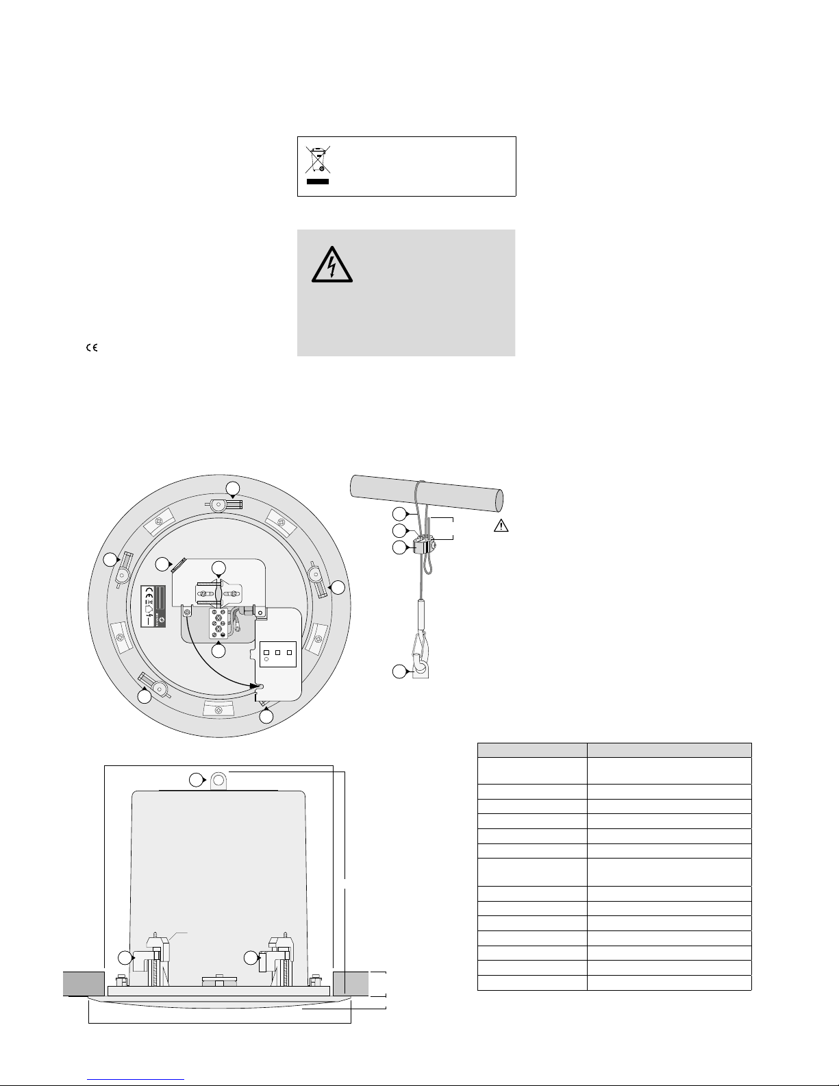
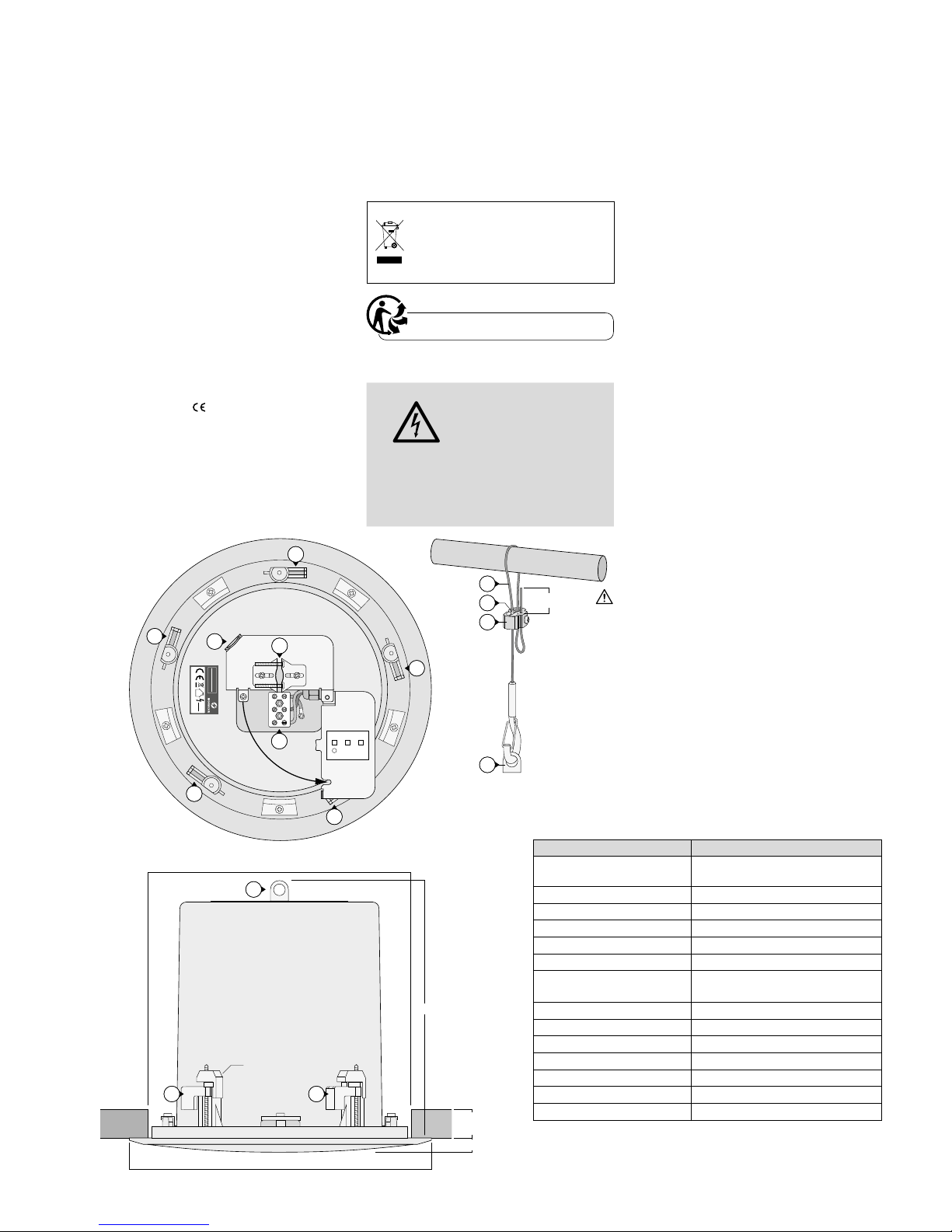
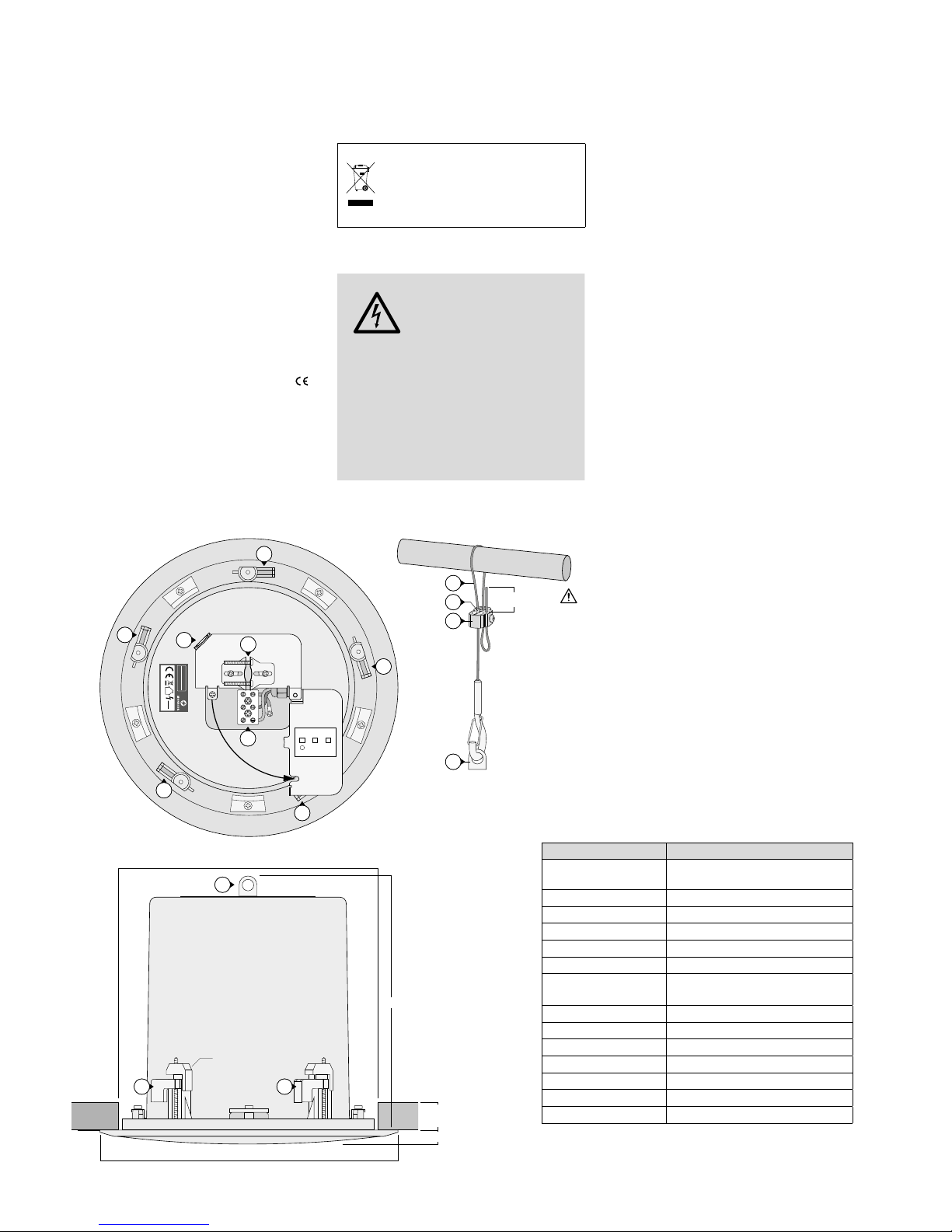
5)
Bei einem Deckeneinbau unbedingt das
beiliegende Fangseil (5) zur Montage-
sicherung anbringen.
a)
Das Seil aus der Seilklemme (7) her-
ausziehen. Dazu die Arretierhülsen (6)
hineindrücken.
b) Das Seil, wie in der Abbildung gezeigt,
an einer mechanisch stabilen Stelle be-
festigen.
c)
Die Seillänge so einstellen, dass bei
einem eventuellen Herausfallen aus der
Decke der Fallweg möglichst kurz ist.
d)
Nach dem Anschließen des Subwoofers
den Karabinerhaken in die Sicherungs-
öse (2) der Subwoofers einhaken.
6)
Das Lautsprecherkabel durch die Kabel-
klemme (3) führen, an die Schraubklem-
men „0“ und „+“ (4) anschließen und mit
der Kabelklemme festklemmen.
7)
Vor dem Einsetzen des Lautsprechers in
das Montageloch sicherstellen, dass sich
die fünf Klemmstücke (1) in ihrer Aus-
gangsposition befinden (siehe Zeichnung
der Draufsicht). Dann den Lautsprecher in
das Loch einsetzen und ihn durch Anzie-
hen der Montageschrauben festklemmen.
8) Das Schutzgitter wieder aufsetzen.
Änderungen vorbehalten.
Technische Daten ESUB-6C/WS
Nennbelastbarkeit 100V: 40/ 20/10W
4 Ω: 55W
Musikbelastbarkeit 110 W
Frequenzbereich 45– 280Hz
Kennschalldruck 88dB (1W/1 m)
Max. Nennschalldruck 104dB
Abstrahlwinkel 180°
Lautsprechertyp Bandpass-Subwoofer mit
16-cm-Langhubmembran (6”)
Deckenstärke 5– 32mm
Einbauöffnung ⌀268mm
Einbautiefe 255mm
Abmessungen ⌀310mm × 265 mm
Gewicht 5kg
Anschluss Keramik-Schraubklemmen
Einsatztemperatur 0–40 °C
Diese Bedienungsanleitung ist urheberrechtlich für MONACOR
®
INTERNATIONAL GmbH & Co. KG geschützt. Eine Reproduktion für
eigene kommerzielle Zwecke – auch auszugsweise – ist untersagt.