5
Deutsch
2 Hinweise
fürdensicherenGebrauch
Das Gerät entspricht allen relevanten Richtlinien
der EU und ist deshalb mit gekennzeichnet.
WARNUNG
Das Gerät wird mit lebensgefähr-
licher Netzspannung versorgt.
Nehmen Sie deshalb niemals
selbst Eingriffe daran vor. Es
besteht die Gefahr eines elek-
trischen Schlages.
•
Verwenden Sie das Gerät nur im Innenbereich
und schützen Sie es vor Tropf- und Spritzwas-
ser, hoher Luftfeuchtigkeit und Hitze (zulässi-
ger Einsatztemperaturbereich 0–40°C).
•
Stellen Sie keine mit Flüssigkeit gefüllten Ge-
fäße, z.B. Trinkgläser, auf das Gerät.
•
Die im Gerät entstehende Wärme muss durch
Luftzirkulation abgegeben werden. Decken
Sie die Lüftungsöffnung (Bassreflexöffnung)
nicht ab.
•
Nehmen Sie das Gerät nicht in Betrieb oder
ziehen Sie sofort den Netzstecker aus der
Steckdose,
1.
wenn sichtbare Schäden am Gerät oder am
Netzkabel vorhanden sind,
2.
wenn nach einem Sturz oder Ähnlichem
der Verdacht auf einen Defekt besteht,
3. wenn Funktionsstörungen auftreten.
Geben Sie das Gerät in jedem Fall zur Repa-
ratur in eine Fachwerkstatt.
•
Ziehen Sie den Netzstecker nie am Kabel aus
der Steckdose, fassen Sie immer am Stecker an.
•
Verwenden Sie für die Reinigung nur ein tro-
ckenes, weiches Tuch, niemals Wasser oder
Chemikalien.
•
Wird das Gerät zweckentfremdet, nicht rich-
tig angeschlossen, falsch bedient oder nicht
fachgerecht repariert, kann keine Haftung für
daraus resultierende Sach- oder Personen-
schäden und keine Garantie für das Gerät
übernommen werden.
Soll das Gerät endgültig aus dem Be-
trieb genommen werden, übergeben
Sie es zur umweltgerechten Entsor-
gung einem örtlichen Recyclingbetrieb.
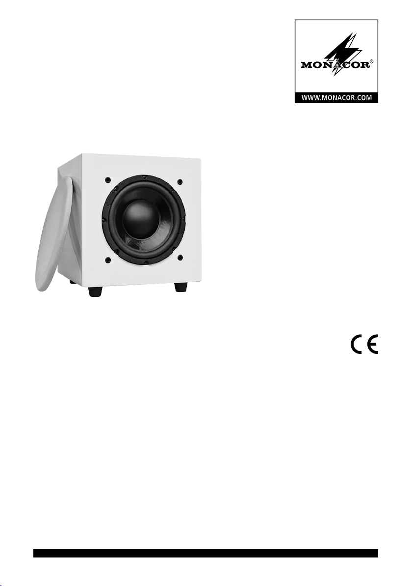
3 Einsatzmöglichkeiten
Dieser kompakte aktive Subwoofer dient als
tieffrequente Ergänzung bestehender Lautspre-
cheranlagen im Hi-Fi-, Heimkino- und Home-
recording-Bereich. Er ist mit einem 20-cm-Bass-
lautsprecher (8”) ausgestattet und sein Verstärker
hat eine Spitzenausgangsleistung von 90W.
Der Subwoofer verfügt über ein einstell-
bares Tiefpassfilter, einen Lautstärkeregler,
eine schaltbare Phasenumkehrung und eine
Stand-by-Automatik.
Es sind zwei Stereo-Eingänge vorhanden
(jeweils mit Durchschleifausgang): ein Eingang
für den Anschluss an einen Ausgang mit Line-
Pegel und ein Eingang für den Anschluss an
einen Lautsprecherausgang.
4 Aufstellen und Anschließen
Den Subwoofer auf einen ebenen Untergrund
stellen. Die genaue Positionierung in der Mitte
zwischen den Stereo-Lautsprechern ist beim
Subwoofer nicht entscheidend, da die von ihm
wiedergegebenen sehr tiefen Frequenzen nicht
genau geortet werden können. Stellen Sie ihn
jedoch nicht zu dicht an Wände oder in Ecken,
weil dies den Frequenzgang verfälscht und die
Wärmeabfuhr des eingebauten Verstärkers be-
hindert. Ebenso darf die Bassreflex-Öffnung auf
der Rückseite nicht abgedeckt werden.
Vor dem Anschluss bzw. vor dem Ändern
bestehender Anschlüsse den Subwoofer und die
anzuschließenden Geräte ausschalten.
Eine Signalquelle über eine der beiden in
den Kapiteln 4.1 und 4.2 beschriebenen An-
schlussmöglichkeiten mit dem Subwoofer ver-
binden.
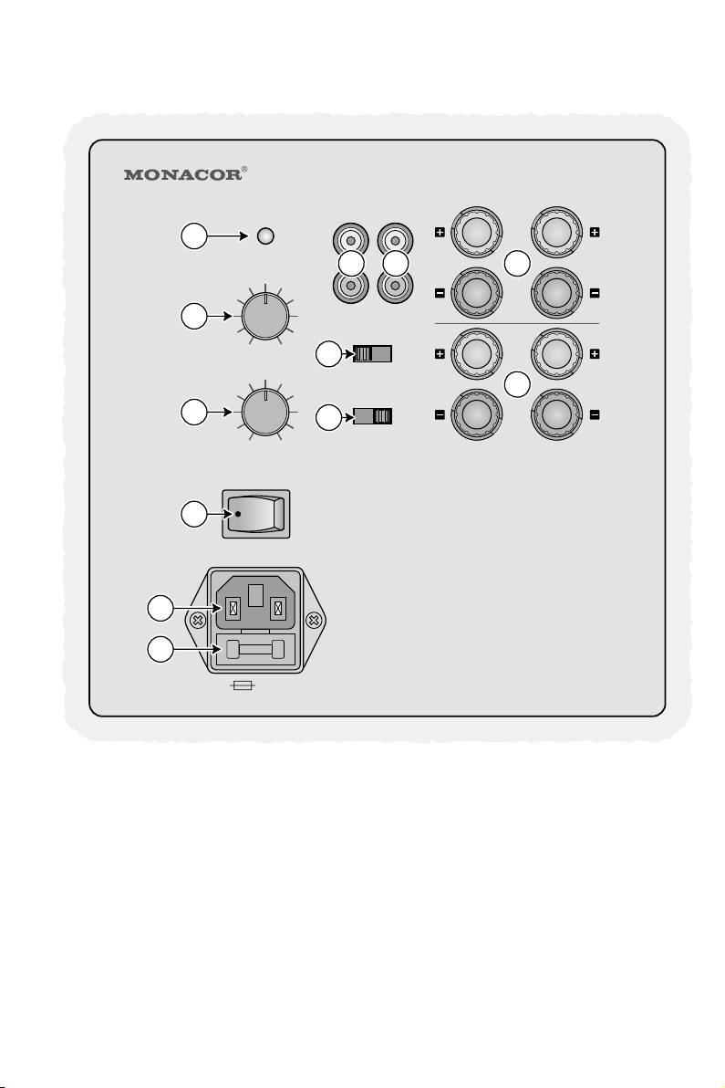
4.1 Stereo-Eingang LINE IN
Ist ein Stereo-Ausgang mit Line-Pegel vorhan-
den (z.B. Ausgang eines Vorverstärkers oder
Mischpults), diesen mit dem Eingang LINE IN
(7) am Subwoofer verbinden. Aus den beiden
Stereo-Kanälen wird intern für den Subwoofer
ein Mono-Signal gebildet.
Sind die Ausgänge des Vorverstärkers oder
Mischpults bereits durch den Anschluss der
vorhandenen Lautsprecheranlage belegt, kann
ein Adapter zur Verzweigung des Ausgangs-
signals verwendet werden (z.B. ACA-120
von MONACOR). Alternativ kann auch der