Montarbo R Series User manual

MANUALE D’USO - SEZIONE 1
USER MANUAL - SECTION 1
BEDIENUNGSANLEITUNG - ABSCHNITT 1
NOTICE D’EMPLOI - SECTION 1
MANUAL DE USO - SECCIÓN 1
1
R108 - R110 - R112 - R115 - R15S - R18S
DIFFUSORI A 2 VIE E SUBWOOFER PROFESSIONALI ATTIVI
ACTIVE 2-WAY LOUDSPEAKERS AND PROFESSIONAL SUBWOOFERS
AKTIVE 2-WEGE-LAUTSPRECHER UND PROFESSIONELLE SUBWOOFER
ENCEINTES À 2 VOIES ET SUBWOOFERS PROFESSIONNELS ACTIFS
ALTAVOCES DE 2 VÍAS Y SUBWOOFERS PROFESIONALES ACTIVOS

32
ITA
manuale d’uso
R SERIES
Grazie per aver acquistato un prodotto Montarbo, azienda italiana fondata nel 1962, da
sempre al servizio della musica e dell’audio professionale. I prodotti Montarbo, originali e
all’avanguardia, sono progettati con la massima attenzione ai dettagli e alla durevolezza
nel tempo. L’adabilità è in linea con gli alti standard qualitativi e la sensibilità all’impatto
ambientale che contraddistinguono l’azienda.
I diffusori attivi della serie R sono
professionali, versatili, ergonomici. La
linea comprende speaker e subwoofer,
ed è quindi adatta all’utilizzo PA
in svariati contesti. La dotazione
di molteplici I/O ne incrementa la
versatilità. Un DSP con 4 preset adatta
le prestazioni acustiche alle diverse
condizioni di utilizzo.
2DOTAZIONI MECCANICHE/ACUSTICHE
Gli speaker sono equipaggiati con un compression driver per le alte frequenze (voice
coil: 1.35” per R108-110, 1,75” per R112-115) ed un trasduttore da 8”, 10”, 12”, e 15”
rispettivamente per R108, R110, R112 e R115. Il design meccanico integra 3 maniglie, oltre
ad una flangia per ssaggio su palo (sul lato inferiore). Oltre a questo, due lati del cabinet,
con inclinazione 40° permettono l’utilizzo come monitor da palco. I subwoofer presentano
rispettivamente un woofer da 15” (R15S) e da 18” (R18S) con voice coil da 4”. Da un punto
di vista meccanico, i subwoofer, oltre ad un adattatore M20 nel lato superiore che consente
il montaggio di uno speaker su palo (non fornito), sono predisposti per il ssaggio di un kit
ruote opzionale per agevolare la movimentazione. Inne per ogni modello sono disponibili,
come optional, cover per trasporto sicuro e protezione rapida dalle intemperie.
3OPZIONI DI CONFIGURAZIONE
1CONTENUTO DELLA CONFEZIONE
1 x Speaker/subwoofer serie R
1 x Manuale d’uso - Sezione 1
1 x Manuale d’uso - Sezione 2
1xCavodialimentazionespecicoperlavostrazonadiutilizzo
INDICE
1CONTENUTO DELLA CONFEZIONE 2
2DOTAZIONI MECCANICHE/ACUSTICHE 3
3 OPZIONI DI CONFIGURAZIONE 3
4 PANNELLO DI CONTROLLO SPEAKER 4
5 PANNELLO DI CONTROLLO SUBWOOFER 6
6 ALIMENTAZIONE 8
7 QUICK SETUP 9
8 ACCESSORI 10
9 ESEMPI DI INSTALLAZIONE 10
10 RISOLUZIONE DEI PROBLEMI 11
11 DATI TECNICI SPEAKER 12
12 DATI TECNICI SUBWOOFER 14
Le avvertenze nel presente manuale devono essere osservate congiuntamente al “MANUALE D’USO - Sezione 2”.
PER ULTERIORI INFORMAZIONI
VEDERE IL CAPITOLO 9

54
ITA
manuale d’uso
R SERIES
6 LEVEL CH2
Questa manopola regola il livello del canale 2, ruotatela verso destra per alzare il livello,
verso sinistra per diminuirlo.
7 PRESET LED
Questi led indicano quale preset è attivo fra PLAYBACK, FLAT, BASS BOOST e WEDGE.
Questi preset sono stati ottimizzati per le diverse applicazioni. PLAYBACK è ideale per
ascolto di audio registrato e/o karaoke, FLAT è ottimo per concerti, BASS BOOST è
perfetto per riproduzione di audio ricco di frequenze basse, quali DJing e musica da
discoteca, mentre WEDGE serve per l’uso come monitor da palco.
8 PRESET
Questo pulsante consente di scegliere fra i quattro preset quello ottimale per
l’applicazione attuale.
9 LED CLIP
Questo led si accende quando il segnale del diffusore è vicino alla distorsione. In questo
caso riducete sia il segnale MAIN che quello dei canali attivi.
10 LED ON
Questo led si accende quando il diffusore è collegato alla rete elettrica e l’interruttore
di accensione è su ON.
11 MAIN OUTPUT
Questa uscita XLR-M fornisce un segnale bilanciato di livello linea, il suo segnale è
stabilito dal relativo selettore.
12 LINK/MIX
Tramite questo selettore potete scegliere se il segnale in uscita verso un altro diffusore
deve essere quello presente negli ingressi (LINK) o quello miscelato fra i tre canali di
ingresso e controllato dal MAIN (MIX).
13 MAIN LEVEL
Questa manopola regola il livello di uscita del diffusore attivo.
4PANNELLO DI CONTROLLO SPEAKER
1 MIC/LINE INPUT
Ingresso combo XLR/jack da 6,35 mm. per segnali microfonici e linea.
2 SELETTORE LINE/MIC
Tramite questo selettore potete regolare la sensibilità dell’ingresso.
3 LEVEL CH1
Questa manopola regola il livello del canale 1, ruotatela verso destra per alzare il livello,
verso sinistra per diminuirlo.
4 LINE INPUT
Ingresso per segnali di livello linea con connettore XLR-F.
5 LINE INPUT
Ingresso per segnali di livello linea con connettore jack da 6,35mm.
1
4
7
5 6
2
3
12
13
11
8
10
9

76
ITA
manuale d’uso
R SERIES
6 CH2 X-OVER OUTPUT
Uscita con crossover per il rilancio del segnale audio ad una testa (speaker).
7 LEVEL
Questa manopola regola il livello di uscita, ruotatela alzare il livello o diminuirlo in
particolare sono indicate le posizioni a 0 dB in caso di sistema singolo (INPUT 1) o
stereo (INPUT 1 + INPUT 2).
8 POLARITY
Permette, se premuto, di invertire la polarità (180°), che normalmente è in posizione 0°.
9 X-OVER
Permette di scegliere la frequenza di crossover per il rilancio del segnale ad una
testa. Premendo il tasto in successione si abilita l’uno o l’altro taglio in frequenza
(80 Hz/100 Hz).
10 LED CLIP
Questo led si accende quando il segnale del subwoofer è vicino alla distorsione. In
questo caso riducete sia il segnale MAIN che quello dei canali attivi.
11 LED ON
Questo led si accende quando il subwoofer è collegato alla rete elettrica e l’interruttore
di accensione è su ON.
5PANNELLO DI CONTROLLO SUBWOOFER
1 CH1 BALANCED INPUT
Ingresso combo XLR/jack da 6,35 mm. per segnali microfonici e linea.
2 CH1 LINK OUTPUT
Uscita di linea per il rilancio del segnale audio.
3 CH1 X-OVER OUTPUT
Uscita con crossover per il rilancio del segnale audio ad una testa (speaker).
4 CH2 BALANCED INPUT
Ingresso combo XLR/jack da 6,35 mm. per segnali microfonici e linea.
5 CH2 LINK OUTPUT
Uscita di linea per il rilancio del segnale audio.
1
2
7
4
5
8
3
6
9
11
10

98
ITA
manuale d’uso
R SERIES
Collocare il diffusore secondo
l’installazione scelta Montare e collegare eventuali gruppi
speaker-subwoofer
Collegare le sorgenti audio agli ingressi
(livelli canali a zero) Effettuare eventuali rilanci ulteriori
Inserire i cavi di alimentazione
ed accendere Regolate tutti i volumi (ed eventuali
crossover) come desiderato
7QUICK SETUP
6ALIMENTAZIONE
1 MAINS INPUT
Presa IEC di ingresso con ltro di rete integrato. Ogni confezione è fornita del cavo di
alimentazione necessario, specico per la vostra area. Con il diffusore spento inserite
in questa presa il cavo per l’alimentazione elettrica. Per la vostra sicurezza, non
scollegate mai il contatto di terra.
2 FUSE
Fusibile di protezione.
ATTENZIONE: Sostituire il fusibile unicamente con uno dello stesso tipo e con gli
stessi valori.
Se il fusibile continua a bruciare, rivolgetevi ad un centro di assistenza autorizzato.
3 POWER ON/OFF
Interruttore per accensione/spegnimento del diffusore attivo.
7.1
7.3
7.5
7.2
7.4
7.6
2 31

1110
ITA
manuale d’uso
R SERIES
palo standard per il montaggio di uno speaker su subwoofer. In questo caso la massima
altezza ammessa tra la base dello speaker e il pavimento dipende anche dal subwoofer
di appoggio. Con R18S: 180 cm (R108-R110) oppure 150 cm (R112-R115). Con R15S:
170 cm (R108), 150 cm (R110-R112), 120 cm (R115). Queste altezze si riferiscono ad
allineamento fronte sub e fronte speaker. Per ogni altra congurazione è necessario un
ssaggio addizionale (non fornito). In caso di rilancio subwoofer – speaker selezionare
l’eventuale crossover.
INSTALLAZIONE CON GOLFARI
E’ possibile installare lo speaker utilizzando ganci eyebolt (golfari). Il posizionamento è
rappresentato nella gura sotto, in cui l’eyebolt posteriore permette di regolare l’angolazione
nale (MAX 45°).
Il posizionamento è intuitivo. Per la diffusione verso una platea seduta o in piedi è consigliato
l’uso di stativi certicati, collocati su una supercie piana e con i cavi di alimentazione e
di segnale posti in modo che non siano calpestabili, né siano tesi, o possano costituire
motivo di inciampo o scarsa sicurezza.
10 RISOLUZIONE DEI PROBLEMI
Lo speaker/subwoofer non si accende
Vericare la presenza della corretta alimentazione a monte dell’impianto.
Vericare che il cavo di alimentazione con connettore VDE sia correttamente inserito.
Lo speaker/subwoofer si accende ma non emette nessun suono
Vericare che i collegamenti agli ingressi dei canali audio (CH1, CH2) siano corretti.
Vericare che i cavi utilizzati non siano interrotti. Utilizzare esclusivamente cavi di qualità
e in buono stato.
Vericare che le sorgenti audio siano accese e indichino segnale in uscita.
Vericare la corretta sensibilità dell’ingresso del CH1 (per gli speaker).
Vericare il volume dell’uscita MAIN (speaker) o LEVEL (subwoofer).
Lo speaker/subwoofer emette un suono di livello basso o distorto:
Regolare il volume delle sorgenti adeguato per gli ingressi della sezione mixer.
Vericare che i cavi utilizzati non siano danneggiati. Utilizzare esclusivamente cavi di
qualità e in buono stato.
Controllare il livello dei volumi degli ingressi e del MAIN (o di LEVEL per il subwoofer).
Attenuare il livello degli ingressi MIC, LINE e/o del MAIN.
Assicuratevi di non aver collegato un segnale di linea al canale 1 con sensibilità MIC.
Vericate i tagli di ltraggio crossover, in caso di rilancio subwoofer-speaker
Presenza di rumore di fondo
Spegnere l’alimentazione e scollegare tutti i dispositivi collegati.
Vericare il segnale di tutte le sorgenti per scoprire quale ha causato il problema.
9ESEMPI DI INSTALLAZIONE
INSTALLAZIONE DI UNO SPEAKER SU STATIVO TREPPIEDE
Il diffusore è installabile su stativo a treppiede opzionale standard con palo di diametro
35 mm. La massima altezza ammessa tra la base dello speaker e il pavimento è 170 cm
per R108, R110, R112 e 150 cm per R115 . Per ogni altro utilizzo è necessario un ssaggio
addizionale (non fornito).
INSTALLAZIONE DI UNO SPEAKER WEDGE
Il diffusore può essere posizionato, usando l’angolazione del cabinet, come monitor live.
In questo caso, si consiglia di selezionare la preselezione WEDGE sul pannello di controllo.
INSTALLAZIONE DI UNO SPEAKER SU SUBWOOFER CON PALO
Utilizzando la predisposizione sul lato superiore del subwoofer, è possibile avvitare un
M8
R108-R110
M10
R112-R115
8ACCESSORI
Coppia di treppiedi Kit da 4 ruote
per i subwoofer
CV-R108/R110/R112/R115/R15S/R18S
cover

1312
ITA
manuale d’uso
R SERIES
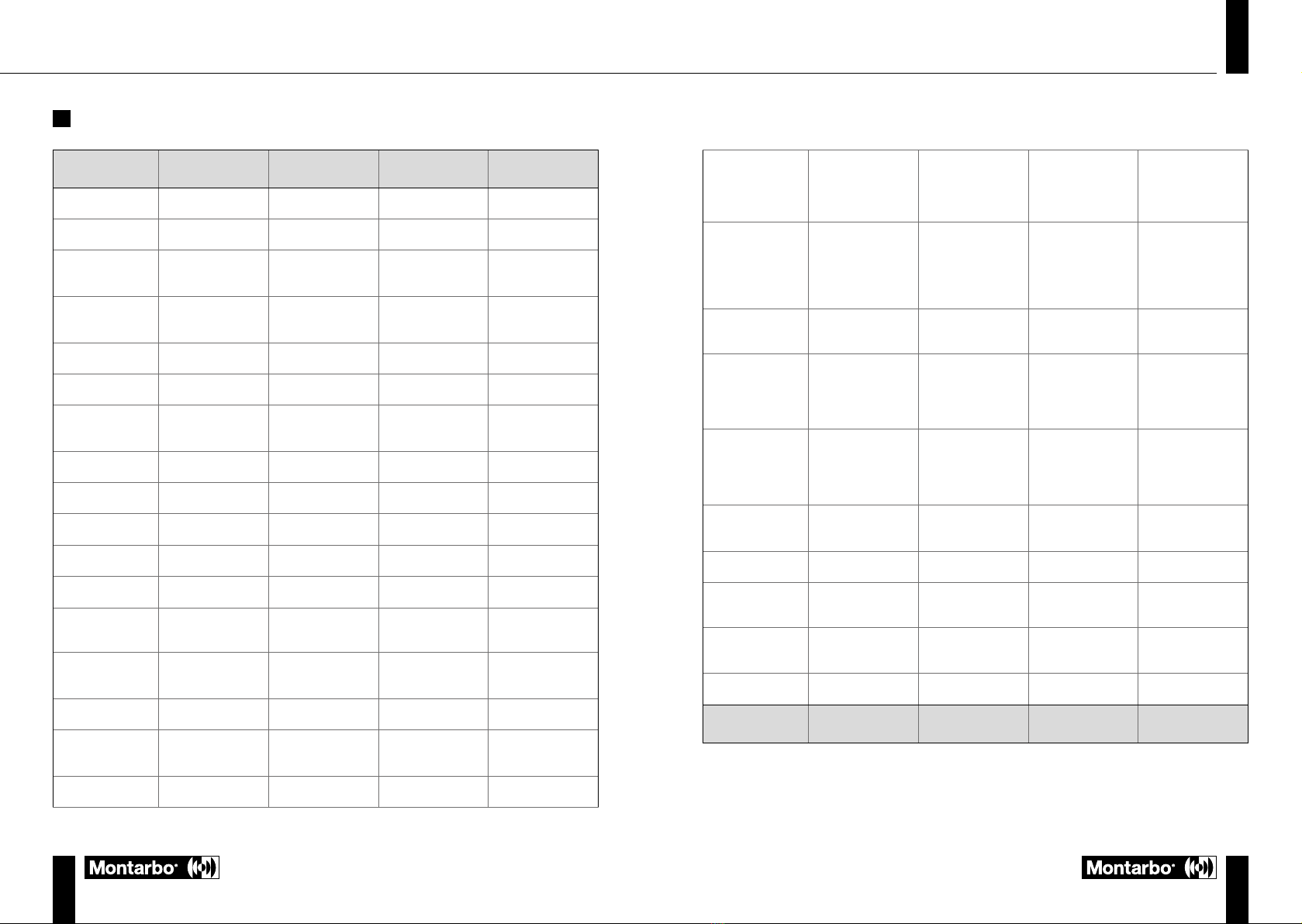
11 DATI TECNICI SPEAKER
MODELLO R 108 R 110 R 112 R 115
TIPOLOGIA
2-vie bass reflex 2-vie bass reflex 2-vie bass reflex 2-vie bass reflex
MAX SPL (@ 1m)
125 dB 127 dB 131 dB 132 dB
Risposta in
frequenza (-10 dB)
63 Hz – 20 kHz 61 Hz – 20 kHz 51 Hz – 20 kHz 48 Hz – 20 kHz
Risposta in
frequenza (-6 dB)
71 Hz – 19 kHz 66 Hz – 19 kHz 56 Hz – 19 kHz 54 Hz – 19 kHz
HF
1.35” driver 1.35” driver 1.75” driver 1.75” driver
LF
8” - 2” V.C 10” - 2” V.C 12” - 3” V.C 15” - 3” V.C
Frequenza di
crossover
1800 Hz 1780 Hz 1500 Hz 1450 Hz
Copertura (H x V)
90°x70° 90°x70° 90°x40° 90°x40°
Classe di
ampicazione
D + A/B D + A/B D D
Potenza RMS
200 W 200 W 600 W 600 W
Potenza di picco
400 W 400 W 1200 W 1200 W
Raffreddamento
Ventola Ventola Radiatore passivo Radiatore passivo
Tensione operativa
110-120V~ 50-60Hz
220-240V~ 50-60Hz
110-120V~ 50-60Hz
220-240V~ 50-60Hz
110-120V~ 50-60Hz
220-240V~ 50-60Hz
110-120V~ 50-60Hz
220-240V~ 50-60Hz
Temperatura
ambiente di
esercizio
-20° +45° -20° +45° -20° +45° -20° +45°
DSP
28/56 bit 28/56 bit 28/56 bit 28/56 bit
Funzioni avanzate
Filtri FIR Filtri FIR Filtri FIR Filtri FIR
Convertitore AD/DA
24 bit, 48 kHz 24 bit, 48 kHz 24 bit, 48 kHz 24 bit, 48 kHz
Connettori I/O
CH1: Combo
CH2: XLR-F +
jack 6,35mm (1/4”)
LINE OUT: XLR-M
CH1: Combo
CH2: XLR-F +
jack 6,35mm (1/4”)
LINE OUT: XLR-M
CH1: Combo
CH2: XLR-F +
jack 6,35mm (1/4”)
LINE OUT: XLR-M
CH1: Combo
CH2: XLR-F +
jack 6,35mm (1/4”)
LINE OUT: XLR-M
Controlli
Livello dei canali
Livello MAIN
PRESET
Sensibilità canale 1
Uscita LINK/MIX
Livello dei canali
Livello MAIN
PRESET
Sensibilità canale 1
Uscita LINK/MIX
Livello dei canali
Livello MAIN
PRESET
Sensibilità canale 1
Uscita LINK/MIX
Livello dei canali
Livello MAIN
PRESET
Sensibilità canale 1
Uscita LINK/MIX
Fusibile
T5A L – 100-120V~
T2.5A L - 220-250V~
T5A L – 100-120V~
T2.5A L - 220-250V~
T6.3A L – 100-120V~
T3.15A L - 220-250V~
T6.3A L – 100-120V~
T3.15A L - 220-250V~
Assorbimento a
1/8 della potenza
(condizioni medie
di utilizzo)
0.6 A (110-120V~)
0.39 A (220-240V~)
0.6 A (110-120V~)
0.39 A (220-240V~)
1.47 A (110-120V~)
0.89 A (220-240V~)
1.47 A (110-120V~)
0.89 A (220-240V~)
Assorbimento a
1/3 della potenza
(condizioni
massime di utilizzo)
1.1 A (110-120V~)
0.85 A (220-240V~)
1.1 A (110-120V~)
0.85 A (220-240V~)
3 A (110-120V~)
1.8 A (220-240V~)
3 A (110-120V~)
1.8 A (220-240V~)
Consumo
in stand-by
18 W 18W 18W 18W
Corrente di inrush
9.5 A 9.5 A 4 A 4 A
Materiale cabinet
Legno multistrato
con nitura poliurea
Legno multistrato
con nitura poliurea
Legno multistrato
con nitura poliurea
Legno multistrato
con nitura poliurea
Dimensioni
(L x H x P)
264 x 440 x 260 mm
10.4” x 17.3” x 10.3”
304 x 505 x 305 mm
11.9” x 19.9” x 14,4”
359 x 610 x 350 mm
14.2” x 24” x 13.8”
427 x 705 x 428 mm
16.8” x 27.8” x 16.9”
Peso
10.9 kg (24 lbs) 12.7 kg (28 lbs) 21 kg (46,3 lbs) 25.9 kg (57 lbs)
MODELLO R 108 R 110 R 112 R 115

1514
ITA
manuale d’uso
R SERIES
Controlli
Livello LEVEL
Selezione XOVER
Selezione POLARITY
Livello LEVEL
Selezione XOVER
Selezione POLARITY
Fusibile
T8A H – 100-120V~
T4A L - 220-250V~
T8A H – 100-120V~
T4A L - 220-250V~
Assorbimento a
1/8 della potenza
(condizioni medie
di utilizzo)
1.5 A (110-120V~)
0.9 A (220-240V~)
1.5 A (110-120V~)
0.9 A (220-240V~)
Assorbimento a
1/3 della potenza
(condizioni
massime di
utilizzo)
1.7 A (110-120V~)
3 A (220-240V~)
1.7 A (110-120V~)
3 A (220-240V~)
Consumo in
stand-by
19 W 19 W
Corrente di inrush
5.7 A 5.7 A
Materiale cabinet
Legno multistrato con nitura poliurea Legno multistrato con nitura poliurea
Dimensioni
(L x H x P)
430 x 580 x 590 mm
16.9” x 22.8” x 23.2”
510 x 650 x 690 mm
20” x 25.6” x 27.2”
Peso
31.9 kg (70.32 lbs) 38 kg (83.8 lbs)
MODELLO R15S R18S
12 DATI TECNICI SUBWOOFER
MODELLO R15S R18S
TIPOLOGIA
Vented – stereo sub Vented – stereo sub
MAX SPL (@ 1m)
130 dB 131,5 dB
Risposta in
frequenza (-10 dB)
45 Hz – Cut freq 41 Hz – Cut freq
Risposta in
frequenza (-6 dB)
48 Hz – Cut freq 44 Hz – Cut freq
LF
15” - 4” V.C 18” - 4” V.C
Classe di
ampicazione
D D
Potenza RMS
500 W 500 W
Potenza di picco
1000 W 1000 W
Raffreddamento
Radiatore passivo Radiatore passivo
Tensione
operativa
110-120V~ 50-60Hz
220-240V~ 50-60Hz
110-120V~ 50-60Hz
220-240V~ 50-60Hz
Temperatura
ambiente di
esercizio
-20° +45° -20° +45°
DSP
28/56 bit 28/56 bit
Convertitore
AD/DA
24 bit, 48 kHz 24 bit, 48 kHz
Connettori I/O
CH1/CH2: Combo
LINE OUT: XRL-M (LINK+XOVER)
CH1/CH2: Combo
LINE OUT: XRL-M (LINK+XOVER)

1716
ENG
user manual
R SERIES
Thank you for purchasing a product created by Montarbo, an Italian company founded in
1962, always at the service of music and professional audio. Montarbo products, original
and avant-garde, are designed with the utmost attention to detail and durability. Reliability is
in line with the high quality standards and sensitivity to environmental impact that distinguish
the company.
The R series active speakers are
professional, versatile, ergonomic.
The line includes speakers and
subwoofers, and is therefore suitable
for PA use in various contexts. The
multiple I/Os enhance their versatility.
A DSP with 4 presets adapts the
acoustic performance to different
conditions of use.
2MECHANICAL/ACOUSTIC FEATURES
The speakers are equipped with a compression driver for high frequencies (voice coil:
1.35” for R108-110, 1.75” for R112-115) and an 8”, 10”, 12”, and 15” transducer for R108,
R110, R112 and R115 respectively. The mechanical design integrates 3 handles, as well
as a pole mounting flange (on the bottom). In addition to this, two sides of the cabinet,
with 40° inclination, allow use as a stage monitor. The subwoofers have a 15” (R15S) and
18” (R18S) woofer with 4” voice coil respectively. From a mechanical point of view, the
subwoofers, in addition to an M20 adapter on the upper side that allows the mounting of
a speaker on a pole (not supplied), are prepared for xing an optional wheel kit to facilitate
handling. Finally, for each model there are optional covers for safe transport and rapid
weather protection.
3CONFIGURATION OPTIONS
1PACKAGE CONTENTS
1 x Speaker/subwoofer series R
1 x User manual - Section 1
1 x User manual - Section 2
1xPowercablespecicforyourareaofuse
CONTENTS
1PACKAGE CONTENTS 16
2MECHANICAL/ACOUSTIC FEATURES 17
3CONFIGURATION OPTIONS 17
4SPEAKER CONTROL PANEL 18
5SUBWOOFER CONTROL PANEL 20
6POWER SUPPLY 22
7QUICK SETUP 23
8ACCESSORIES 24
9EXAMPLES OF INSTALLATION 24
10 TROUBLESHOOTING 25
11 SPEAKER TECHNICAL DATA 26
12 SUBWOOFER TECHNICAL DATA 28
The warnings in this manual must be observed in conjunction with the “USER MANUAL - Section 2”.
FOR FURTHER INFORMATION
SEE CHAPTER 9

1918
ENG
user manual
R SERIES
6 CH2 LEVEL
This knob adjusts the level of channel 2, turn it to the right to raise the level, to the left
to lower it.
7 PRESET LED
These LEDs indicate which preset is active between PLAYBACK, FLAT, BASS BOOST
and WEDGE.
These presets have been optimized for different applications. PLAYBACK is ideal for
listening to recorded audio and/or karaoke, FLAT is great for concerts, BASS BOOST
is perfect for playing rich low frequency audio, such as DJing and disco music, while
WEDGE is for use as a stage monitor.
8 PRESET
This button allows you to choose the optimal preset for your current application from
the four presets.
9 CLIP LED
This LED lights up when the speaker signal is close to distortion. In this case reduce
both the MAIN signal and the active channels signal.
10 ON LED
This LED lights up when the speaker is connected to the mains and the power switch
is ON.
11 MAIN OUTPUT
This XLR-M output provides a balanced line level signal, its signal is set by its selector
switch.
12 LINK/MIX
Through this selector you can choose whether the output signal to another speaker
must be the one present in the inputs (LINK) or the one mixed between the three input
channels and controlled by the MAIN (MIX).
13 MAIN LEVEL
This knob adjusts the output level of the active speaker.
4SPEAKER CONTROL PANEL
1 MIC/LINE INPUT
6.35 mm XLR/jack combo input for microphone and line signals.
2 LINE/MIC SELECTOR SWITCH
This selector switch can be used to adjust the input sensitivity.
3 CH1 LEVEL
This knob adjusts the level of channel 1, turn it to the right to raise the level, to the left
to lower it.
4 LINE INPUT
Input for line level signals with XLR-F connector.
5 LINE INPUT
Input for line level signals with 6.35 mm jack connector.
1
4
7
5 6
2
3
12
13
11
8
10
9

2120
ENG
user manual
R SERIES
6 CH2 X-OVER OUTPUT
Crossover output for linking the audio signal to one head (speaker)
7 LEVEL
This knob adjusts the output level, turn it to raise the level or lower it. In particular the
positions at 0 dB are indicated in the case of single system (INPUT 1) or stereo (INPUT
1 + INPUT 2).
8 POLARITY
If pressed, it allows you to invert the polarity (180°), which is normally in the 0° position.
9 X-OVER
Allows you to choose the crossover frequency for linking the signal to one
head. Pressing the key in succession enables one or the other cut-off frequency
(80 Hz/100 Hz).
10 CLIP LED
This LED lights up when the subwoofer signal is close to distortion. In this case reduce
both the MAIN signal and the active channels signal.
11 ON LED
This LED lights up when the subwoofer is connected to the mains and the power
switch is ON.
5SUBWOOFER CONTROL PANEL
1 CH1 BALANCED INPUT
6.35mm XLR/jack combo input for microphone and line signals.
2 CH1 LINK OUTPUT
Line output for audio signal link.
3 CH1 X-OVER OUTPUT
Crossover output for linking the audio signal to one head (speaker)
4 CH2 BALANCED INPUT
6.35mm XLR/jack combo input for microphone and line signals.
5 CH2 LINK OUTPUT
Line output for audio signal link.
1
2
7
4
5
8
3
6
9
11
10

2322
ENG
user manual
R SERIES
7QUICK SETUP
6POWER SUPPLY
1 MAINS INPUT
IEC input socket with integrated mains lter. Each package is supplied with the
necessary power cable, specic for your area. With the speaker off, plug the power
cable into this socket. For your own safety, never disconnect the ground contact.
2 FUSE
Protection fuse.
CAUTION: Only replace the fuse with one of the same type and with the same rating.
If the fuse keeps blowing, contact an authorised service centre.
3 POWER ON/OFF
Switch for switching the active speaker on/off.
Place the speaker according to the
chosen installation Assemble and connect any speaker-
subwoofer groups
Connect the audio sources to the
inputs (channel levels at zero) Make any further links
Insert the power cables and switch on Adjust all volumes (and any crossovers)
as desired
7.1
7.3
7.5
7.2
7.4
7.6
2 31

2524
ENG
user manual
R SERIES
9EXAMPLES OF INSTALLATION
INSTALLATION OF A SPEAKER ON A TRIPOD STAND
The speaker can be installed on an optional standard tripod stand with 35 mm diameter
pole. The maximum permissible height between the speaker base and the floor is 170 cm
for R108, R110, R112 and 150 cm for R115. Any other use requires additional xing (not
supplied).
INSTALLATION OF A WEDGE SPEAKER
The speaker can be positioned, using the angle of the cabinet, as a live monitor. In this
case, we recommend selecting the WEDGE preset on the control panel.
INSTALLATION OF A SPEAKER ON A SUBWOOFER WITH POLE
Byusingthe prearrangementonthetop ofthesubwoofer, itispossibletoscrewonastandard
8ACCESSORIES
Pair of tripods Kit of 4 wheels
for subwoofers
CV-R108/R110/R112/R115/R15S/R18S
cover
pole for mounting a speaker on a subwoofer. In this case the maximum permissible height
between the base of the speaker and the floor also depends on the supporting subwoofer.
With R18S: 180 cm (R108-R110) or 150 cm (R112-R115). With R15S: 170 cm (R108), 150
cm (R110-R112), 120 cm (R115). These heights refer to the alignment of the sub front and
speaker front. Any other conguration requires additional xing (not supplied). In the case
of a subwoofer - speaker link, select the possible crossover.
INSTALLATION WITH EYEBOLTS
The speaker can also be installed using eyebolts. The positioning is shown in the gure on
the side, where the rear eyebolt allows adjusting the nal angle (MAX 45°).
Positioning is intuitive. For amplifying to a seated or standing audience, the use of certied
stands is recommended, placed on a flat surface and with power and signal cables placed
so that they cannot be walked on, are not stretched and cannot present a risk of tripping
or poor safety.
10 TROUBLESHOOTING
The speaker/subwoofer does not power up
Check that there is a correct power supply upstream from the system.
Check that the power cable with VDE connector is plugged in properly.
The speaker/subwoofer powers up but does not emit any sound
Check that the connections to the audio channel inputs (CH1, CH2) are correct.
Check that the cables used are not interrupted. Use only quality cables in good condition.
Check that the audio sources are switched on and show an output signal.
Check that the input sensitivity of CH1 (for speakers) is correct.
Check the volume of the MAIN (speaker) or LEVEL (subwoofer) output.
The speaker/subwoofer emits low or distorted sound:
Adjust the appropriate source volume for the mixer section inputs.
Check that the cables used are not damaged. Use only quality cables in good condition.
Check the volume level of the inputs and the MAIN (or LEVEL for the subwoofer).
Lower the level of the MIC, LINE and/or MAIN inputs.
Make sure you have not connected a line signal to channel 1 with MIC sensitivity.
Check the crossover lter cuts, in case of a subwoofer-speaker link
Presence of background noise
Turn off the power and disconnect all connected devices.
Check the signal from all sources to nd out which one caused the problem.
M8
R108-R110
M10
R112-R115
2726
ENG
user manual
R SERIES
11 SPEAKER
TECHNICAL DATA
MODEL R 108 R 110 R 112 R 115
TYPE
2-way bass reflex 2-way bass reflex 2-way bass reflex 2-way bass reflex
MAX SPL (@ 1m)
125 dB 127 dB 131 dB 132 dB
Frequency response
(-10 dB)
63 Hz – 20 kHz 61 Hz – 20 kHz 51 Hz – 20 kHz 48 Hz – 20 kHz
Frequency response
(-6 dB]
71 Hz – 19 kHz 66 Hz – 19 kHz 56 Hz – 19 kHz 54 Hz – 19 kHz
HF
1.35” driver 1.35” driver 1.75” driver 1.75” driver
LF
8” - 2” V.C 10” - 2” V.C 12” - 3” V.C 15” - 3” V.C
Crossover
frequency
1800 Hz 1780 Hz 1500 Hz 1450 Hz
Coverage (H x V)
90°x70° 90°x70° 90°x40° 90°x40°
Amplicationclass
D + A/B D + A/B D D
RMS power
200 W 200 W 600 W 600 W
Peak power
400 W 400 W 1200 W 1200 W
Cooling
Fan Fan Passive radiator Passive radiator
Operating voltage
110-120V~ 50-60Hz
220-240V~ 50-60Hz
110-120V~ 50-60Hz
220-240V~ 50-60Hz
110-120V~ 50-60Hz
220-240V~ 50-60Hz
110-120V~ 50-60Hz
220-240V~ 50-60Hz
Operating ambient
temperature
-20° +45° -20° +45° -20° +45° -20° +45°
DSP
28/56 bit 28/56 bit 28/56 bit 28/56 bit
Advanced
functions
FIR lters FIR lters FIR lters FIR lters
AD/DA converter
24 bit, 48 kHz 24 bit, 48 kHz 24 bit, 48 kHz 24 bit, 48 kHz
I/O connectors
CH1: Combo
CH2: XLR-F +
6.35 mm jack (1/4”)
LINE OUT: XLR-M
CH1: Combo
CH2: XLR-F +
6.35mm jack (1/4”)
LINE OUT: XLR-M
CH1: Combo
CH2: XLR-F +
6.35 mm jack (1/4”)
LINE OUT: XLR-M
CH1: Combo
CH2: XLR-F +
6.35mm jack (1/4”)
LINE OUT: XLR-M
Controls
Channel level
MAIN level
PRESET
Channel 1 sensitivity
LINK/MIX output
Channel level
MAIN level
PRESET
Channel 1 sensitivity
LINK/MIX output
Channel level
MAIN level
PRESET
Channel 1 sensitivity
LINK/MIX output
Channel level
MAIN level
PRESET
Channel 1 sensitivity
LINK/MIX output
Fuse
T5A L – 100-120V~
T2.5A L - 220-250V~
T5A L – 100-120V~
T2.5A L - 220-250V~
T6.3A L – 100-120V~
T3.15A L - 220-250V~
T6.3A L – 100-120V~
T3.15A L - 220-250V~
Consumption at
1/8 of the power
(medium
conditions of use)
0.6 A (110-120V~)
0.39 A (220-240V~)
0.6 A (110-120V~)
0.39 A (220-240V~)
1.47 A (110-120V~)
0.89 A (220-240V~)
1.47 A (110-120V~)
0.89 A (220-240V~)
Consumption
at 1/3 of the
power (maximum
conditions of use)
1.1 A (110-120V~)
0.85 A (220-240V~)
1.1 A (110-120V~)
0.85 A (220-240V~)
3 A (110-120V~)
1.8 A (220-240V~)
3 A (110-120V~)
1.8 A (220-240V~)
Consumption
in stand-by
18 W 18W 18W 18W
Inrush current
9.5 A 9.5 A 4 A 4 A
Cabinet material
Multilayer wood
with polyurea nish
Multilayer wood
with polyurea nish
Multilayer wood
with polyurea nish
Multilayer wood
with polyurea nish
Dimensions
(W x H x D)
264 x 440 x 260 mm
10.4” x 17.3” x 10.3”
304 x 505 x 305 mm
11.9” x 19.9” x 14,4”
359 x 610 x 350 mm
14.2” x 24” x 13.8”
427 x 705 x 428 mm
16.8” x 27.8” x 16.9”
Weight
10.9 kg (24 lbs) 12.7 kg (28 lbs) 21 kg (46,3 lbs) 25.9 kg (57 lbs)
MODEL R 108 R 110 R 112 R 115

2928
ENG
user manual
R SERIES
12
SUBWOOFER TECHNICAL DATA
Controls
LEVEL
XOVER selection
POLARITY selection
LEVEL
XOVER selection
POLARITY selection
Fuse
T8A H – 100-120V~
T4A L - 220-250V~
T8A H – 100-120V~
T4A L - 220-250V~
Consumption
at 1/8 of the
power (medium
conditions of use)
1.5 A (110-120V~)
0.9 A (220-240V~)
1.5 A (110-120V~)
0.9 A (220-240V~)
Consumption
at 1/3 of the
power (maximum
conditions of use)
1.7 A (110-120V~)
3 A (220-240V~)
1.7 A (110-120V~)
3 A (220-240V~)
Consumption in
stand-by
19 W 19 W
Inrush current
5.7 A 5.7 A
Cabinet material
Multilayer wood with polyurea nish Multilayer wood with polyurea nish
Dimensions
(W x H x D)
430 x 580 x 590 mm
16.9” x 22.8” x 23.2”
510 x 650 x 690 mm
20” x 25.6” x 27.2”
Weight
31.9 kg (70.32 lbs) 38 kg (83.8 lbs)
MODEL R15S R18S
MODEL R15S R18S
TYPE
Vented – stereo sub Vented – stereo sub
MAX SPL (@ 1m)
130 dB 131.5 dB
Frequency
response (-10 dB)
45 Hz – Cut freq 41 Hz – Cut freq
Frequency
response (-6 dB]
48 Hz – Cut freq 44 Hz – Cut freq
LF
15” - 4” V.C 18” - 4” V.C
Amplication
class
D D
RMS power
500 W 500 W
Peak power
1000 W 1000 W
Cooling
Passive radiator Passive radiator
Operating voltage
110-120V~ 50-60Hz
220-240V~ 50-60Hz
110-120V~ 50-60Hz
220-240V~ 50-60Hz
Operating ambient
temperature
-20° +45° -20° +45°
DSP
28/56 bit 28/56 bit
AD/DA converter
24 bit, 48 kHz 24 bit, 48 kHz
I/O connectors
CH1/CH2: Combo
LINE OUT: XRL-M (LINK+XOVER)
CH1/CH2: Combo
LINE OUT: XRL-M (LINK+XOVER)

3130
DEU
Bedienungsanleitung
R SERIES
Danke, dass Sie ein Produkt der italienischen Firma Montarbo erworben haben, die seit 1962
im Dienst von Musik und professionellen Audioausrüstungen steht. Die ausgereiften und
fortschrittlichen Montarbo Produkte sind auf größte Detailpege und Langlebigkeit ausgelegt.
Die Zuverlässigkeit entspricht den hohen Qualitätsstandards und dem Umweltbewusstsein
im Einklang mit den Kernwerten der Firma.
Die aktiven Lautsprecher der Serie R sind
professionell, vielseitig, ergonomisch.
Die Produktlinie umfasst Lautsprecher
und Subwoofer, sie eignet sich daher
für PA-Anlagen in verschiedenen
Anwendungen. Die Ausstattung
mit vielfachen Ein- und Ausgängen
erhöht ihre Vielseitigkeit. Ein DSP
mit 4 Presets stimmt die akustischen
Leistungswerte auf die verschiedenen
Einsatzbedingungen ab.
2MECHANISCHE/AKUSTISCHE KOMPONENTEN
Die Lautsprecher verfügen über einen Kompressionstreiber für die hohen Frequenzen
(Schwingspule: 1.35” für R108-110, 1,75” für R112-115) und einen 8”, 10”, 12”, sowie 15”
Wandler jeweils für R108, R110, R112 und R115. Die mechanische Konstruktion beinhaltet
3 integrierte Griffe sowie einen Flansch zur Säulenbefestigung (an der Unterseite). Darüber
hinaus ermöglichen zwei Gehäuseseiten mit 40° Neigung den Einsatz als Bühnenmonitor.
Die Subwoofer verfügen jeweils über einen 15” (R15S) bzw. 18” Woofer (R18S) mit 4”
Schwingspule. Was die Mechanik betrifft, sind sie mit einem M20 Adapter an der Oberseite
zur Säulenbefestigung eines Lautsprechers (Säule nicht im Lieferumfang inbegriffen)
ausgestattet und für die Befestigung eines optionalen Räder-Kits für den einfachen
Transport vorgesehen. Für jedes Modell sind außerdem auf Wunsch Abdeckungen für
sicheren Transport und schnell installierbaren Witterungsschutz erhältlich.
3KONFIGURATIONSOPTIONEN
WEITERE INFORMATIONEN
FINDEN SICH IN KAPITEL 9
1LIEFERUMFANG
1 x Lautsprecher/Subwoofer Serie R
1 x Bedienungsanleitung - Kapitel 1
1 x Bedienungsanleitung - Kapitel 2
1 x Spezielles Versorgungskabel für Ihr Einsatzgebiet
INHALTSVERZEICHNIS
1LIEFERUMFANG 30
2MECHANISCHE/AKUSTISCHE KOMPONENTEN 31
3KONFIGURATIONSOPTIONEN 31
4BEDIENFELD LAUTSPRECHER 32
5BEDIENFELD SUBWOOFER 34
6STROMVERSORGUNG 36
7QUICK SETUP 37
8ZUBEHÖR 38
9INSTALLATIONSBEISPIELE 38
10 FEHLERBEHEBUNG 39
11 TECHNISCHE DATEN LAUTSPRECHER 40
12 TECHNISCHE DATEN SUBWOOFER 42
Die Hinweise in der vorliegenden Bedienungsanleitung sind ebenso zu befolgen wie die in der
„BEDIENUNGSANLEITUNG – Kapitel 2“.

3332
DEU
Bedienungsanleitung
R SERIES
6 LEVEL CH2
Dieser Regler regelt den Pegel von Kanal 2; zum Anheben der Verstärkung nach rechts
drehen, zur Absenkung nach links drehen.
7 PRESET LED
Diese LEDs weisen auf das jeweils aktive Preset hin, und zwar PLAYBACK, FLAT, BASS
BOOST und WEDGE.
Diese Presets sind für die verschiedenen Anwendungen optimiert. PLAYBACK ist ideal
für die Wiedergabe von Audioaufnahmen und/oder Karaoke, FLAT für Konzerte, BASS
BOOST für die Wiedergabe von Audio mit Tieffrequenzen wie DJing und Disko-Musik,
WEDGE dient dagegen beim Einsatz als Bühnenmonitor.
8 PRESET
Mit diesem Knopf kann aus vier Presets das jeweils für die gewünschte Anwendung
optimale gewählt.
9 LED CLIP
Diese LED leuchtet auf, wenn das Lautsprechersignal nahezu verzerrt ist. In einem
solchenFallsowohl MAIN-Signalals auch das Signalder aktiven Kanäleherunterdrehen.
10 LED ON
Diese LED leuchtet auf, wenn der Lautsprecher an das Stromnetz angeschlossen und
der Einschalter auf ON ist.
11 MAIN OUTPUT
Dieser Ausgang XLR-M stellt ein symmetrisches Line-Pegelsignal bereit, wobei das
Signal durch den entsprechenden Wahlschalter deniert wird.
12 LINK/MIX
MitdiesemWahlschalterkann festgelegtwerden,obdaszu einem anderenLautsprecher
ausgehende Signal dem an den Eingängen (LINK) anliegenden oder dem unter den
drei Eingangskanälen gemischten und von MAIN gesteuerten Signal entsprechen soll
(MIX).
13 MAIN LEVEL
Dieser Regler regelt den Ausgangspegel des aktiven Lautsprechers.
4BEDIENFELD LAUTSPRECHER
1 MIC/LINE INPUT
Combo-Eingang XLR/Klinke 6,35 mm für Mikrofon- und Line-Signale.
2 WAHLSCHALTER LINE/MIC
Mit diesem Wahlschalter kann die Empndlichkeit des Eingangs eingestellt werden.
3 LEVEL CH1
Dieser Regler regelt den Pegel von Kanal 1; zum Anheben der Verstärkung nach rechts
drehen, zur Absenkung nach links drehen.
4 LINE INPUT
Eingang für Line-Pegelsignale mit Buchse XLR-F.
5 LINE INPUT
Eingang für Line-Pegelsignale mit Klinkenstecker 6,35mm.
1
4
7
5 6
2
3
12
13
11
8
10
9

3534
DEU
Bedienungsanleitung
R SERIES
6 CH2 X-OVER OUTPUT
Ausgang mit Crossover für die Weiterleitung des Audiosignals an ein Kopfstück
(Lautsprecher).
7 LEVEL
Dieser Regler regelt den Ausgangspegel, zum Anheben bzw. Absenken des Pegels
drehen. Im Besonderen sind die Stellungen auf 0dB für Einzelsysteme (INPUT 1) oder
mit Stereo Weiterleitung (INPUT 1 + INPUT 2) angezeigt.
8 POLARITY
Dient in gedrückter Stellung zum Umkehren der Polarität (180°), normalerweise in
Stellung 0°.
9 X-OVER
Dient zur Wahl der Übergangsfrequenz zur Weiterleitung des Audiosignals an ein
Kopfstück. Durch mehrmaliges Drücken der Taste wird zwischen zwei Grenzfrequenzen
gewechselt (80 Hz/100 Hz).
10 LED CLIP
Diese LED leuchtet auf, wenn das Subwoofersignal nahezu verzerrt ist. In einem solchen
Fall sowohl MAIN-Signal als auch das Signal der aktiven Kanäle herunterdrehen.
11 LED ON
Diese LED leuchtet auf, wenn der Subwoofer an das Stromnetz angeschlossen und der
Einschalter auf ON ist.
5BEDIENFELD SUBWOOFER
1 CH1 BALANCED INPUT
Combo-Eingang XLR/Klinke 6,35 mm für Mikrofon- und Line-Signale.
2 CH1 LINK OUTPUT
Line-Out-Ausgang für die Weiterleitung des Audiosignals.
3 CH1 X-OVER OUTPUT
Ausgang mit Crossover für die Weiterleitung des Audiosignals an ein Kopfstück
(Lautsprecher).
4 CH2 BALANCED INPUT
Combo-Eingang XLR/Klinke 6,35 mm für Mikrofon- und Line-Signale.
5 CH2 LINK OUTPUT
Line-Out-Ausgang für die Weiterleitung des Audiosignals.
1
2
7
4
5
8
3
6
9
11
10

3736
DEU
Bedienungsanleitung
R SERIES
7QUICK SETUP
6STROMVERSORGUNG
1 MAINS INPUT
IEC-Eingang mit integriertem Netzlter. In jeder Verpackung mitgeliefert wird ein
für das jeweilige Gebiet geeignetes Stromversorgungskabel. Schließen Sie bei
ausgeschaltetem Lautsprecher das Stromkabel an diesen Eingang an. Zu Ihrer
Sicherheit niemals den Erdungskontakt trennen.
2 FUSE
Schutzsicherung.
ACHTUNG: Sicherung nur mit einer Sicherung des gleichen Typs und mit denselben
Werten ersetzen.
Wenden Sie sich an eine autorisierte Servicestelle, falls die Sicherung weiterhin
durchbrennt.
3 POWER ON/OFF
Schalter zum Ein-/Ausschalten des aktiven Lautsprechers.
Platzieren Sie den Lautsprecher
entsprechend der gewünschten Installation
Montieren Sie eventuelle Lautsprecher-/
Subwoofer-Einheiten montieren und
schließen Sie sie an.
Schließen Sie die Audioquellen an die
Eingänge (Kanalpegel auf Null) an
Führen Sie eventuelle weitere
Weiterleitungen durch
Schließen Sie die Stromkabel an und
schalten Sie den Lautsprecher ein
Stellen Sie die gewünschte Lautstärke (und
eventuelle Crossover) ein
7.1
7.3
7.5
7.2
7.4
7.6
2 31

3938
DEU
Bedienungsanleitung
R SERIES
9INSTALLATIONSBEISPIELE
INSTALLATION EINES LAUTSPRECHERS AUF STATIV
Der Lautsprecher kann auf das optionale Stativ mit standardmäßigem Säulendurchmesser
35 mm installiert werden. Die maximal zulässige Höhe zwischen Lautsprecherbasis und
Boden beträgt 170cm für R108, R110, R112 und 150cm für R115. Für jeden weiteren
Einsatz ist eine zusätzliche Befestigung erforderlich (nicht im Lieferumfang).
INSTALLATION EINES WEDGE-LAUTSPRECHERS
Der Lautsprecher kann mithilfe der geneigten Gehäuseausführung als Live-Monitor
platziert werden. In diesem Fall sollte das Preset WEDGE am Bedienfeld gewählt werden.
INSTALLATION EINES LAUTSPRECHERS AUF SUBWOOFER MIT STÄNDER
Mithilfe der Vorrüstung an der Oberseite des Subwoofers kann eine Standardsäule für
8ZUBEHÖR
Zwei Stative Kit mit 4 Rädern
für die Subwoofer
CV-R108/R110/R112/R115/R15S/R18S
cover
die Montage eines Lautsprechers auf Subwoofer festgeschraubt werden. In diesem Fall
hängt die maximal zulässige Höhe zwischen Lautsprecherbasis und Boden auch vom
tragenden Subwoofer ab. Mit R18S: 180cm (R108-R110) oder 150cm (R112-R115). Mit
R15S: 170 cm (R108), 150 cm (R110-R112), 120 cm (R115). Diese Höhen beziehen sich
auf die Ausrichtung Subwoofer-Frontseite und Lautsprecher-Frontseite. Für jede andere
Konguration ist eine zusätzliche Befestigung erforderlich (nicht im Lieferumfang). Bei
Weiterleitung Subwoofer – Speaker das eventuelle Crossover auswählen.
INSTALLATION MIT RINGSCHRAUBEN
Der Lautsprecher kann unter Anwendung der Eyebolt-Haken (Ringschrauben) installiert
werden. Die Positionierung wird auf der nebenstehenden Abbildung dargestellt, wo der
hintere Eyebolt eine Regulierung des Endwinkels (MAX. 45°) ermöglicht.
Die Aufstellung ist intuitiv. Für die Wiedergabe zu einem sitzenden oder stehenden
Publikum empehlt sich die Verwendung zertizierter Stative auf ebener Oberfläche,
wobei Versorgungs- und Signalkabel so zu verlegen sind, dass sie weder begehbar noch
gespannt sind und keine Stolpergefahr bzw. keine Sicherheitsgefährdung darstellen.
10 FEHLERBEHEBUNG
Der Lautsprecher/Subwoofer lässt sich nicht einschalten
Überprüfen, ob der Lautsprecher korrekt mit der Stromversorgung verbunden ist.
Überprüfen, ob das Stromversorgungskabel mit VDE-Stecker korrekt eingesteckt ist.
Der Lautsprecher/Subwoofer lässt sich zwar einschalten, doch es kommt kein Ton
Überprüfen, ob die Anschlüsse an den Eingängen der Audiokanäle (CH1, CH2)
korrekt sind.
Überprüfen, ob die verwendeten Kabel unversehrt sind. Ausschließlich hochwertige
Kabel in perfektem Zustand verwenden.
Überprüfen, ob die Audioquellen eingeschaltet sind und ein Ausgangssignal liefern.
Die korrekte Eingangsempndlichkeit von CH1 überprüfen (für die Lautsprecher).
Die Lautstärke des Ausgangs MAIN (Lautsprecher) bzw. LEVEL (Subwoofer) überprüfen.
Der Klang aus dem Lautsprecher/Subwoofer ist leise oder verzerrt:
Die für die Eingänge des Mixers geeignete Lautstärke der Quellen einstellen.
Überprüfen, ob die verwendeten Kabel beschädigt sind. Ausschließlich hochwertige
Kabel in perfektem Zustand verwenden.
Lautstärkepegel der Eingänge und des MAIN (bzw. LEVEL für den Subwoofer) überprüfen.
Pegel der Eingänge MIC, LINE und/oder MAIN niedriger drehen.
Sicherstellen, dass kein Line-Signal am Kanal 1 mit MIC-Empndlichkeit anliegt.
Bei Weiterleitung Subwoofer-Lautsprecher die Crossover-Grenzfrequenzen prüfen
Hintergrundgeräusche
Die Stromversorgung unterbrechen und alle angeschlossenen Geräte trennen.
Das Signal sämtlicher Quellen überprüfen, um die Störungsursache lokalisieren
zu können.
M8
R108-R110
M10
R112-R115
This manual suits for next models
6
Table of contents
Languages:
Other Montarbo Subwoofer manuals

Montarbo
Montarbo 112 SA User manual

Montarbo
Montarbo 215 SA User manual

Montarbo
Montarbo BX182A Instruction manual

Montarbo
Montarbo SW 540 User manual

Montarbo
Montarbo 218 SA User manual

Montarbo
Montarbo TANK12SA User manual

Montarbo
Montarbo SW 540 User manual

Montarbo
Montarbo 119SA User manual

Montarbo
Montarbo Earth 118 User manual

Montarbo
Montarbo EARTH 218 User manual


