Monoprice 16116 User manual


2
CONTENTS
SAFETY WARNINGS AND GUIDELINES.......................................................................................................................................3
CUSTOMER SERVICE.................................................................................................................................................................................... 3
PACKAGE CONTENTS.................................................................................................................................................................................4
ASSEMBLY AND INSTALLATION.......................................................................................................................................................5
TECHNICAL SUPPORT...............................................................................................................................................................................14
SPECIFICATIONS............................................................................................................................................................................................14

3
SAFETY WARNINGS AND GUIDELINES
Please read this entire manual before using this device, paying extra attention to these
safety warnings and guidelines. Please keep this manual in a safe place for future reference.
Ensure that any surface this cart will be placed on is sufficiently robust to support
the combined weight of the cart and installed displays, as well as that of any
persons moving the cart into place.
This cart can support four displays weighing up to 100 lbs. (45kg) each for a total of
400 lbs. (181kg). Exceeding the rated weight capacity can result in damage to the
equipment or severe personal injury.
Visually inspect the cart periodically and after it is transported to ensure that all
parts are secure and that all screws are tight. Do not use the cart if any parts are
damaged or missing.
Do not install anything other than four flat-screen displays on this cart. Other loads
could change the center of balance and cause the cart to tip over, resulting in
equipment damage and possible serious injury.
While much of this cart can be assembled by a single person, final assembly, display
installation, and final adjustment should be performed by two people.
CUSTOMER SERVICE
The Monoprice Customer Service department is dedicated to ensuring that your ordering,
purchasing, and delivery experience is second to none. If you have any problem with your
order, please give us an opportunity to make it right. You can contact a Monoprice
Customer Service representative through the Live Chat link on our website
www.monoprice.com during normal business hours (Mon-Fri: 5am-7pm PT, Sat-Sun: 9am-

4
PACKAGE CONTENTS
Please take an inventory of the package contents to ensure you have all the items listed
below. If anything is missing or damaged, please contact Monoprice Customer Service for a
replacement.

5
ASSEMBLY AND INSTALLATION
1. For ten of the twelve 4040 Corner pieces,
attach two T-Nuts using two M8x20
Combination Screws. Tighten the screws
slightly by hand, leaving a 3mm gap between
the Corner and the T-Nut, as shown in the
accompanying drawing. These corner
assemblies will be referred to as Ordinary 4040
Corner Assemblies.

6
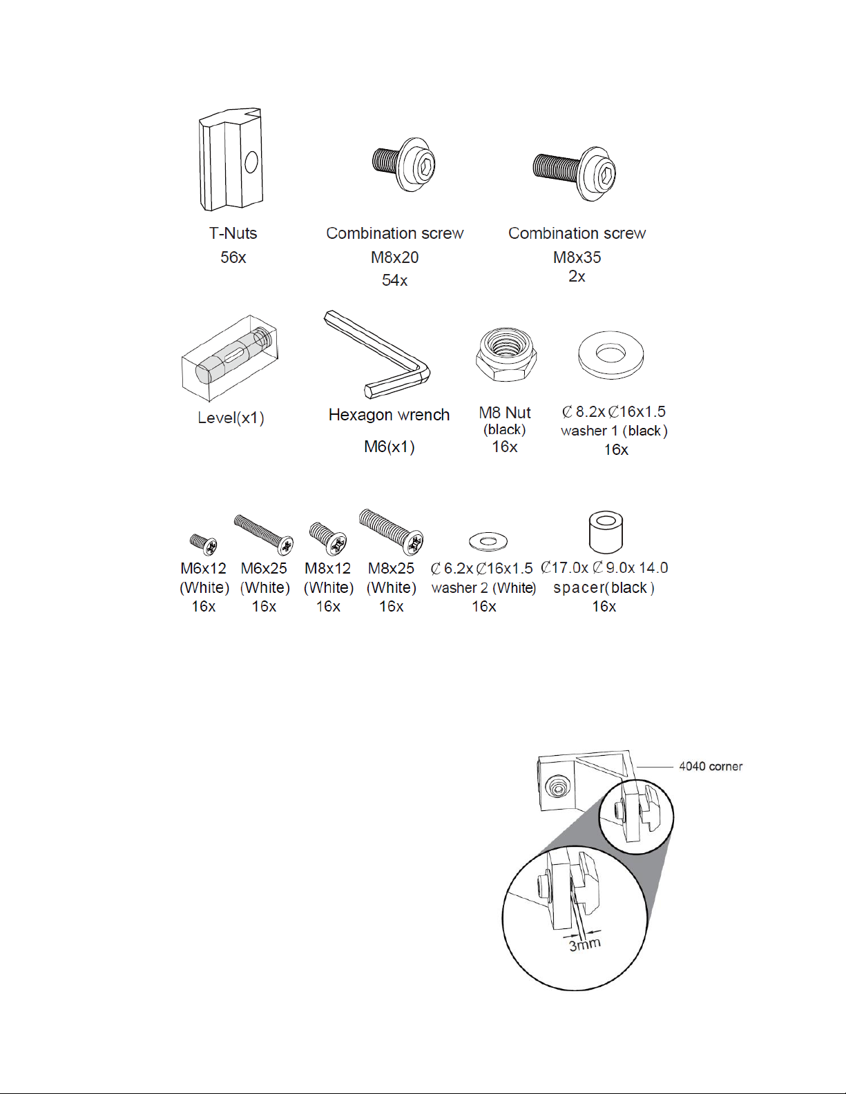
2. For the remaining two 4040 Corner pieces, attach one T-Nut using an M8x20
Combination Screw, then attach a second T-Nut using one M8x35 Combination
Screw. Tighten the M8x35 Combination Screw until the end of the screw is flush
with the back of the T-Nut. This will result in a larger than 3mm gap, but will be
necessary when attaching the lower Beam to the two Base Bars. These two 4040
Corner assemblies will be referred to as Special 4040 Corner Assemblies.
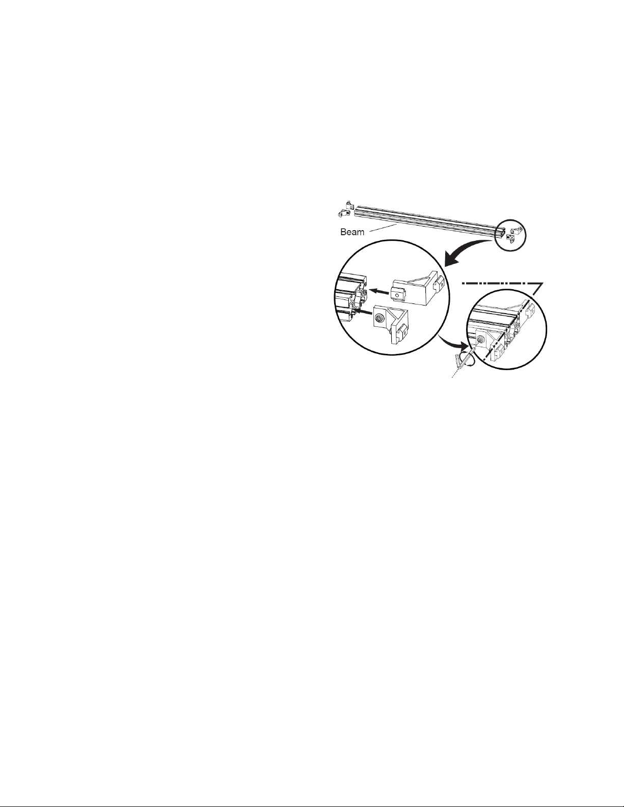
3. Create two Upper Beam Assemblies by
attaching four Ordinary 4040 Corner
Assemblies. To do this, align the T-Nut
with the groove in the Beam and slide
the Corner Assembly into the groove
until the exposed side of the Corner
Assembly is flush with the end of the
Beam. Tighten the M8x20 Combination
Screws on the T-Nuts inserted into the
Beam grooves using the included M6
Hexagonal Wrench.
4. Create one Lower Beam Assembly by attaching two Ordinary 4040 Corner
Assemblies on one side of the Beam, using the instructions in step 3 above. Then
attach the two Special 4040 Corner Assemblies to the other side of the Beam, with
the sides with the M8x35 Combination Screws on the outside. Ensure the exposed
side of each corner assembly is flush with the ends of the Beam, then tighten the
M8x20 Combination Screws on the T-Nuts inserted into the Beam grooves using the
included M6 Hexagonal Wrench.
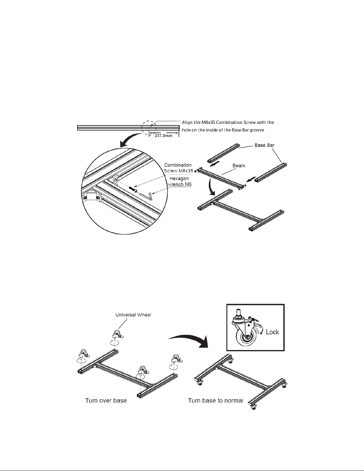
5. Examine each of the two Base Bars. Inside one of the grooves on each, at a distance
of 237mm from the end, is an unthreaded hole. This hole is used to properly position
the Lower Beam Assembly on the Base Bars. Align the T-Nut with the M8x35
Combination Screw into the groove on one of the Base Bars, then slide the Lower
Beam Assembly onto the Base Bar until the M8x35 Combination Screw is aligned
with the hole on the inside of the groove. Ensure that the beam is located on the
short side of the hole in the Base Bar, then tighten the M8x35 Combination Screw
using the M6 Hexagonal Wrench. The screw will extend into the hole, thereby

7
properly positioning and securing the Lower Beam Assembly onto the Base Bar.
Next, tighten the M8x20 Combination Screw on the other side of the Lower Beam
Assembly using the M6 Hexagonal Wrench. Using the same procedure, attach the
other Base Bar to the other end of the Lower Beam Assembly. Ensure that the
caster holes on the Base Bars are all on the same side. Note that the short side is the
back of the cart.
6. Position the Base Assembly with the caster holes up. Depress the locking lever on
each Universal Wheel to lock the wheel. Insert a Universal Wheel into one of the
caster holes on the Base Bars and turn it clockwise to screw it into the Base Bar.
Repeat with the other three Universal Wheels. Flip the Base Assembly over to rest
on the casters.

8
7. Using the same procedure as in step 1 above, attach four T-Nuts to each 8080
Corner piece using four M8x20 Combination Screws.
8. Create two Upright Assemblies by attaching two 8080 Corner Assemblies to one
end of each Upright piece using the same procedure as in step 3 above. Ensure the
exposed sides of the 8080 Corner Assemblies are flush with the end of the Upright,
then tighten the M8x20 Combination Screws using the M6 Hexagonal Wrench.
9. Align the T-Nuts on one
of the Upright
Assemblies, then slide it
into the two grooves on
top of one of the Base
Bars on the Base
Assembly. Align the
Upright Assembly with
the Lower Beam
Assembly, as shown in
the accompanying
illustration. Tighten the M8x20 Combination Screws using the M6 Hexagonal
Wrench. Install the second Upright Assembly onto the other side of the Base
Assembly using the same procedure.

9
10. Align the T-Nuts on one of the
Upper Beam Assemblies, then
slide the Beam Assembly into
the grooves on the insides of the
two Upright Assemblies, as
shown. Position the bottom of
the Upper Beam Assembly about
670mm (26.4") above the top of
the Base Assembly, then tighten
the M8x20 Combinations Screws
using the M6 Hexagonal Wrench.
Note that the 670mm distance does not have to be exact, but each side of the
Upper Beam assembly should be exactly the same distance above the Base
Assembly. Use the included Level as necessary.
11. Attach four T-Nuts to the inside of each of the four Wall Plate Adapters using the
same procedure as in step 1 above.
12. Align the T-Nuts on one of the Wall Plate Adapter Assemblies, then slide it onto one
of the Upright Assemblies, with the solid side facing forward, as shown. Tighten the
M8x20 Combination screws using the M6 Hexagonal Wrench. Install a second Wall
Plate Adapter Assembly to the other Upright Assembly, at the same height as the
first, then secure it in place.

10
13. Using two people, lift one of the Wall Plates and place it on the threaded rods on
the front of the Wall Plate Adapter Assemblies. For each threaded rod, install one
ø8.2xø16x1.5 Washer 1 and one M8 Nut. After all washers and nuts have been
installed onto the threaded rods, use the included Level to ensure the Wall Plate is
level, then tighten the M8 Nuts using an appropriate wrench (not included).
14. Using the same procedure as in step 10 above,
install the second Upper Beam Assembly onto
the two Upright Assemblies.
15. Using the same procedure as in step 12 above,
install the two remaining Wall plate Adapter
Assemblies onto the two Upright Assemblies.
16. Using the same procedure as in step 13 above,
install the second Wall Plate onto the second
pair of Wall Plate Adapter Assemblies.
17. Measure the vertical height of your displays.

11
18. Using two people, slightly loosen the screws on the upper Wall Plate Adapter
Assemblies and adjust the distance between the top of each Wall Plate to match
the height of your displays, then tighten the screws to secure the Wall Plate
Assembly in place.
19. Spread a blanket or towel out on the floor, a table, or other flat surface. Place one
of your displays face down on the blanket/towel.
20. Locate the VESA mounting holes on the back of the display. Using one M6x12 Screw
and one M8x12 Screw, determine which screw fits the VESA holes. Place one of the
Right Monitor Brackets over the two VESA holes on the left side of the display.
Position the bracket so that it is centered on the two vertical VESA holes. If the
bracket is not flush against the holes or if the holes are recessed into the back of
the display, you will need to use the ø17.0xø9.0x14.0 Spacers between the bracket
and the back of the display. If using the spacers, you will need to use the M6x25
Screws or the M8x25 Screws, otherwise use the M6x12 Screws or the M8x12 Screws
to secure the bracket to the back of the display. Be sure and use the ø6.2xø16x1.5
Washers 2 on the screws. Next, install one of the Left Monitor Brackets onto the
holes on the right side of the display. The brackets are properly installed when the
adjustment knobs are at the top and on the outside of the brackets. Refer to the
illustration on the next page.

12
21. Repeat step 20 to install the Mounting Brackets on the other three displays.
22. Using two people, lift one of the displays and hook the Mount Brackets onto the
lower Wall Plate on the right side. Slide the display left or right until the left side is
at the center of the Wall Plate. Repeat the process to place the remaining displays
on the Wall Plates.

13
23. Ensure that all displays are properly positioned, then move around to the back and
tighten the screws at the bottom of each bracket to secure the bracket to the Wall
Plate.
24. Each Monitor Bracket has two knobs for
fine tuning the positioning in or out and
up or down. Use the adjustment knobs
as necessary to fine tune the
positioning of each display. The
adjustment range is 20mm.
25. Install End Caps at the each end of the Base Bars and
at the top of the Upright Assemblies. Avoid excessive
force to prevent damage to the End Caps.
Congratulations, your 2x2 Video Cart is ready for use!

14
TECHNICAL SUPPORT
Monoprice is pleased to provide free, live, online technical support to assist you with any
questions you may have about installation, setup, troubleshooting, or product
recommendations. If you ever need assistance with your new product, please come online
to talk to one of our friendly and knowledgeable Tech Support Associates. Technical
support is available through the online chat button on our website www.monoprice.com
during regular business hours, 7 days a week. You can also get assistance through email by
sending a message to tech@monoprice.com
SPECIFICATIONS
Model
16116
Number of Displays
4
Minimum Display Size
32"
Maximum Display Size
55"
Minimum VESA Size
75 x 75
Maximum VESA Size
600 x 400
Weight Capacity
100 lbs. (45 kg) per display / 400 lbs. (181 kg) total
Weight
58.4 lbs. (26.5 kg)
Table of contents
Popular Outdoor Cart manuals by other brands

Brinly
Brinly PCT-17BH owner's manual

Landmann
Landmann 82427 Assembly and use instructions

Briggs & Stratton
Briggs & Stratton Snapper XD owner's manual

MyBinding
MyBinding Luxor LE42C-B instruction manual

Aqua Creek Products
Aqua Creek Products F-MTTC manual

Office Star Products
Office Star Products WorkSmart DOL8000 operating instructions