Monosem DM-4600 User manual

TABLE OF CONTENTS
OPERATOR’S MANUAL
DM-4600
Monosem, Inc.
1001 Blake St.
Edwardsville, KS 66111
(913) 438-1700
www.monosem-inc.com

OPERATOR’S MANUAL
2
DM-4600
NOTES:

OPERATOR’S MANUAL
3
DM-4600
Table of Contents
System Overview .......................................................................................................................... 4
Specifications ............................................................................................................................ 5
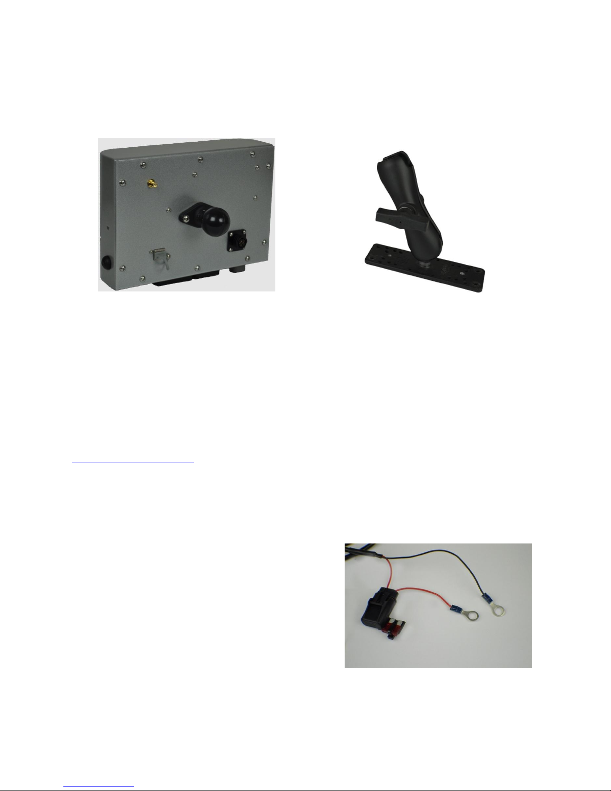
Installation ........................................................................................................................... 6-7
Quick Start ................................................................................................................................8-13
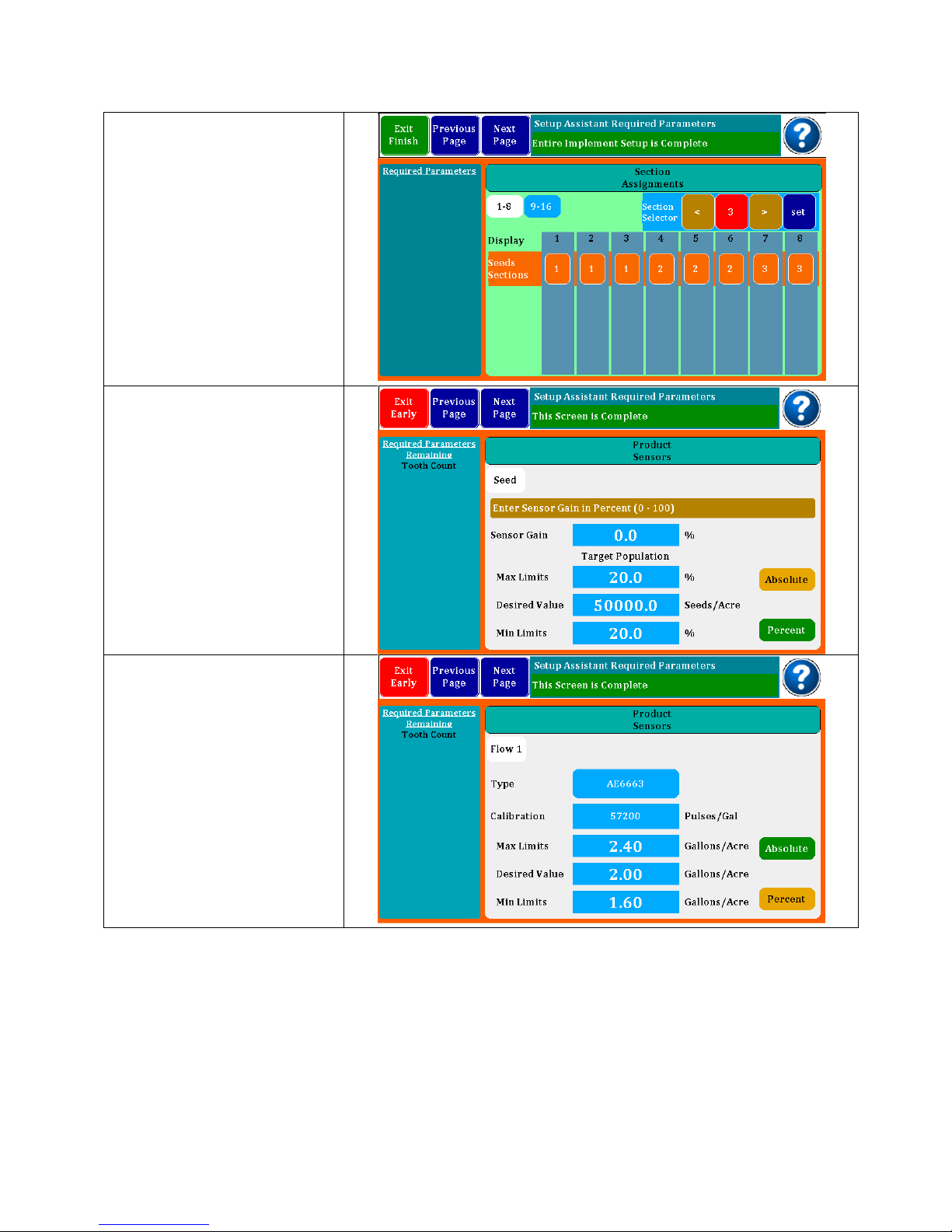
Implement Setup....................................................................................................................... 8
Sensor Setup ........................................................................................................................... 8-9
Target Rates............................................................................................................................. 10
Accessories and Options .................................................................................................. 11-12
Speed Setup ....................................................................................................................... 12-13
Monitor Operations..................................................................................................................... 14
Home Screen...................................................................................................................... 14-15
Dash View ........................................................................................................................... 16-17
Singulation Screen .................................................................................................................. 18
MPH Indicator.......................................................................................................................... 19
Internal GPS Status.................................................................................................................. 20
Lift Switch Configuration / Hopper Type Sensor Setup ...................................................... 21
VAC/Pressure Sensor Setup .............................................................................................. 22-23
Flow meter installation ..........................................................................................................24-27
Master Flow Sensor.................................................................................................................. 28
Post Season Storage............................................................................................................... 29
Harness Pinouts ...................................................................................................................... 30-32
Parts and Accessories...........................................................................................................33-34
Warranty....................................................................................................................................... 36

OPERATOR’S MANUAL
4
DM-4600
INTRODUCTION
System Overview
The DM-4600 Planter Monitor is designed for maximum performance in the field and is
easy to install and use. The system is capable of monitoring up to 32 rows and provides
not only seed population, but also will display area, and has capabilities of monitoring
liquid flow with Monosem “Visu-Flo Technology”.
7” Color Touch Screen
DM-4600 1-32 Row Monitoring
Built in GPS Speed option
Bar graphs
Setup assist for easy programming
Adjustable accumulating time
RAM 1 1/2” Ball Mount
Adjustable Back light
Day/Night Mode
Adjustable Audible Alarm
Optional Visual Alarm Light
View Home or Dashboard
View Seed population or GPM
View 20 sec. Row History
Visu-Flo Option
Optional Lift Switch
2 Hopper Level, 2 RPM, 2 Vac. Opt.
Section grouping

OPERATOR’S MANUAL
5
DM-4600
SPECIFICATIONS
Power
10–16 VDC, 3.5 A maximum
Operating
temperature range
-20°C to 70°C (-4°F to 158°F)
Storage temperature
range
-40°C to 85°C (-40°F to 185°F)
Size
24.1 cm W x 18 cm H x 6.8 cm D (9.5"
W x 7" H x 2.7" D)
Weight
3.58 kg (7.9 lb) for 32-row
DM-4600system
WireHarnesses
The DM-4600 includes detachable
harnesses to supply the unit's power
(fused) and sensor inputs (to hitch).
Connectors on the back for GPS
Antenna, USB and Radar (4 pin)
Sensors
Compatible with Monosem and other
major brands of seed sensors.
Standardmounting
RAM Mount 1
½
” Ball Mounting
Alarm adjustment
Four levels audible alarm with mute
onscreen selection. Optional external light
available.
Backlight adjustment
Five increments plus Day/Night mode
SAFETY NOTICES

OPERATOR’S MANUAL
6
DM-4600
INSTALLATION
Your DM-4600 comes with a RAM 1 ½” Mounting Ball. Any RAM Mount 1 ½” fixtures will
adapt to your monitor.
Optional RAM Base Mount
Part Number: 301108
Install the RAM-238-U 1 ½” Ball supplied with your console by removing the two screws
from the rear of the unit and use them to attach the ball.
Any RAM configuration may be used to attach your console to a convenient location in
your cab. If you need a base mount, see the above for the optional 301108 base. See
your local dealer for brackets and arms that are available, or visit
www.agdirectusa.com to purchase online.
MONITOR AND POWER CONNECTIONS (Harness 301104)
Route the power leads of the main harness to the battery. Allow some slack to tie the
harness off to a secure location in the cab to provide strain relief and for the protection
of the harness.
The monitor operates on 12 VDC only. The red
(Fused) lead should be connected to the
positive battery terminal and the black lead
should be connected to the negative battery
terminal.
There is a short two pin Deutsch connector at the monitor end of the power cord. This
is for connecting the optional Visual Alarm Light (Part No. 301109)

OPERATOR’S MANUAL
7
DM-4600
DM-4600 CONSOLE MAIN HARNESS (Harness 301106)
Route the main harness to the rear of the tractor. Attach the connector to the bottom
of the monitor with a ¼” nut driver. Tie the harness securely in the cab as a strain relief.
The 301106 harness will attach to your planter with a 37 pin AMP CPC style connector.
This connector is pinned to match standards used by Monosem.
If you are using an external speed source such as a radar or external GPS, connect it to
the 4 pin AMP connector on the back of the monitor. (Adapters are available for most
common radar and GPS connectors)
If you are using the internal GPS, attach the antenna to the coax connector on the
back of the monitor.
Once your implement is connected, you are ready to operate your monitor.
INTERNAL GPS
The DM-4600 comes with the onboard GPS enabled.

OPERATOR’S MANUAL
8
DM-4600
QUICK START
Turn monitor on by depressing the On/Off Switch on the right end panel.
The first screen on an
original startup will take
you directly to the Setup
Assistant screen shown at
right. You will find a list of
required parameters on
the left and red boxes that
need to be filled in on the
right.
Touch the Sensors on Row
box and this pop up
screen will appear.
Choose from any
combination of Seed or
Flow inputs. Select No
Sensors if only using the
monitor for an acre
counter.
Selecting Flow 1 or Flow 2
will offer an additional
option of individual row
flow meters or a single
master flow meter. After
the desired configuration
is set, touch “OK” in top
right of pop up screen.
(Ref Master flow meter set
up on pg. 28)

OPERATOR’S MANUAL
9
DM-4600
Continue by entering the
number of rows, row
spacing and implement
width. The Implement
Name may be
personalized using the
pop-up keyboard.
Select the Next Page to
continue to Sensor
Configuration.
From the display
assignments screen, you
can change types of
sensors manually or
configure skip row setups.
To open a configuration
box, touch on one of the
rows in this screen. This will
bring up the planter matrix
where changes can be
entered.
Touch any of the vertical
bars in the above screen
to bring up the manual
assignment screen. Here
you can touch an input
and change sensors or
skip rows. Screen at right
shows a 12 row seed
monitor with 12 flow
meters and two different
flow rates. The funnel is for
flow blockage sensors
often used on air seeders.

OPERATOR’S MANUAL
10
DM-4600
Section assignments may
be entered in this screen.
If you have a planter or
liquid system that is setup
with section shutoff’s, you
can configure the rows to
match so the monitor will
recognize the shutoffs and
not report continuous row
failures. Select section
number at top, then touch
the row pad to add it to
that section.
The product sensors screen
is where target rates are
entered and limits are
assigned. For seeds, set
the desired value and
default is +/- 20%. You
may change percentages
or enter absolute numbers.
If one or more flow inputs
are selected, you must
select the flowmeter part
number (found on your
flowmeters) and then
enter the desired GPA
along with the limits. The
calibration number is auto
generated. If you have
two flow inputs, you will
scroll to flow 2 setup where
you will repeat the above
steps.

OPERATOR’S MANUAL
11
DM-4600
If you have RPM,
VAC/Pressure, Lift Switch
or Hopper Level sensors,
you will need to scroll to
those setups where you
will enter the required
information similar to what
you have done in seed
and flow sensor setup.
(Ref Accessory Sensor set
up on pg.21 and pg.22)
Alarm setup screens are
next. With the first one you
set the volume followed
by a screen where alarms
for accessory sensors may
be disabled or enabled.
The Display setup is where
the screen brightness and
Day/Night Mode are set.
Conversion units may be
set to English or Metric.
Show IO Numbers when
enabled will show the
actual input pin number
on the bar graph row
indicators. This is normally
set to No.

OPERATOR’S MANUAL
12
DM-4600
Sensitivity is the amount of
averaging time used to
calculate rates. The
longer times may show
more accuracy, but
changes will come less
often. This is normally set to
Low or Medium.
The Speed Input screen is
where you select what will
be your primary source of
speed. You can select
Manual where you enter a
number for the speed you
are driving; Radar is used
when an external Radar or
GPS device is plugged into
the 4 pin port on the back
of the monitor. The third
choice is the Internal GPS
when enabled. Speed
Input Alarms may be set
for over speed.
When using an external
Radar or GPS, you will
need to calibrate the
device. This is done by
driving a 400 foot course.
It is suggested that you do
4 runs and the monitor will
store and average them
for you. Flag your course
and as you pass the first
flag, press Start.

OPERATOR’S MANUAL
13
DM-4600
When you pass the
second flag, press End. A
calibration number will
appear in the Run # box.
Continue to do three more
runs to get an accurate
number. The monitor will
average the numbers and
press Save to keep the
calibration number.
Speed derived by this
calibration will be quite
accurate.
Exit the Setup Assistant
and go to the Home
screen. This brings up the
Bar Graph Screen. The
Bar Graph Screen will give
you a visual indication of
each row and showing
over or under rates
compared to average.
There is an information
screen that will show Min-
Max-Ave as well as other
information
Speed/Area Mode
provides a very simple
screen that calculates the
acres covered. Selection
and Configuration of this
mode is very similar to
selection and
configuration of other
Seed/Flow implements. In
the Setup Screen select an
Implement then press on
the associated Sensors on
Row Icon area. This will
bring up the new “Select
the Implement
Configuration” dialog box.
In this dialog select the
check box at the bottom,
the check box text is “No
Sensors”.
After selecting an Implement with No Sensors, the Setup
screens will be reduced to other setup requirements. You
may navigate to the Area/Speed screen by pressing the
Home Button at the top of the Monitor. In the Area/Speed
screen you will get a count of Acres. This count can be
Started or Stopped with the Enable/Disable buttons. You
may also reset the Acre count at any time.

OPERATOR’S MANUAL
14
DM-4600
OPERATING YOUR MONITOR
Once your monitor is configured, you may choose to work from one of the screens on
the previous page.
Getting around the Home Screen….
The three buttons at the top left select the screen. Here we are looking at the Home or
Bar Graph Screen. Seeds and Flow bring up the appropriate Dash View while Setup
takes you back to the setup mode. Speed is displayed to the right and the indicator
showing the type of speed input is displayed. Above figure showing Radar or External
GPS input.
Next, you will find the Information Box and the View Selection buttons. Shown above is
a monitor set for Seed and Flow with two rates. The Avg. View button is selected
showing the Average of each of the applications, Seeds, Flow 1 and Flow 2.
By selecting Seeds, Flow 1 or Flow
2, you bring up a menu box shown
at the right end of the screen.
Shown at right are the three types
of screens you may see for any
product.
The first selection gives the option
of selecting a row and parking on
it. The second shows Min-Max-Avg
for the product and the last shows
a 20 second moving line graph
history of a selected row.

OPERATOR’S MANUAL
15
DM-4600
The bar graphs will change color when the limits are exceeded either over or under as
shown below.
Limits exceeded:
The alarm may be temporarily silenced by holding down the individual row until it
changes color. The small alarm bell will have a circle/red X over it showing that the row
has been silenced. It may be returned to normal operation by holding the row down
again.
THE DASH SCREEN - SEEDS
The Seeds Dash Screen gives a quick overview of the operation. Shown at left is
Population in Seeds/Acre with the Average, the Minimum (Row Number) and Maximum
(Row Number).
Alarm indicator

OPERATOR’S MANUAL
16
DM-4600
Next is Spacing in inches with Average, Minimum (Row Number) and Maximum (Row
Number).
Across the top you will find the acre counters. There are three acre counter memories
in the system and they may be started, stopped or reset by holding the button down for
three seconds to bring up a Start/Stop and Reset button.
On the center right is the Acre/Hr. reading and the Singulation screen showing skips and
multiples.
The Seed Dash Board now allows the user to configure the 3 tiles on the bottom right as
RPM, Vacuum, Pressure or toggling Vac/Pressure. Simply press on the Tiles and a dialog
box will appear with possible Tile assignments.
With the VAC and Pressure capabilities, Tiles are available on the Seed and Flow
Dashboards. Tile Assignments will be saved for future power up cycles. All configurable
Tiles in the Dash boards are now identified with a small peel flip icon in the lower right
corner of the Tile.

OPERATOR’S MANUAL
17
DM-4600
THE DASH SCREEN –FLOW
The Flow Dash Screen is similar to the seeds screen. Shown at left is the Flow Rate. It will
Show GPA Average, Minimum (Row Number) and Maximum (Row Number). If you
have two Flows selected, there will be a second column for Flow 2.
Across the top you will find the acre counters. There are three acre counter memories
in the system and they may be started, stopped or reset by holding the button down for
three seconds to bring up a Start/Stop and Reset button. Shown above, a triangle
shows acres counting, whereas a square indicates counter has stopped.
Center right shows Acre/Hour rate followed by a calculated Field Flow 1 and Total Flow
1. Both of these may be started/stopped or cleared by holding the button down for
three seconds.
On the bottom row you will see the current average GPM flow rate (This will toggle
between Flow 1 and Flow 2 if you have both) and finally, you have Field Flow 2 and
Total Flow 2 which may be started/stopped or cleared by holding the button down for
three seconds.
The center lower 2 tiles can be configured with existing Acres/Hr, Flow GPM and the
new Pressure or Vac sensor values. Simply press on the Tiles and a dialog box will
appear with possible Tile Assignments.

OPERATOR’S MANUAL
18
DM-4600
THE SINGULATION SCREEN
The Singulation Screen provides row by row Singulation conditions. To enter this screen
navigate to the Seed Dashboard and press on the Singulation cell, you will be taken to
the Row Singulation screen.
After entering the screen you will have a view very similar to the Home Screen. The
screen has a console or statistics area, a view select area and a graphical area. The
view select area lets you chose from 3 different console statistics, Row Select, Max
Value, and Overall average. The Row Select shows the Singulation, Skips and Double of
the selected row, these values represent a percentage singulation. Press on the Row
Graphical area to select which Row to view. The Max Value shows the Row number
and Max value in percent of Skips and Multiples. The Row count value is a count of all
rows that are exhibiting Skips and Multiples. The Overall Average view contains the
values normal scene on the Seed Dashboard screen.
For each row graphical object you can see the present Skips and Multiple percentages.
Skips are shown in yellow above the center line and Multiples are shown in Red below
the center line. If neither of these colors show for a given Row this would indicate 100 %
singulation.

OPERATOR’S MANUAL
19
DM-4600
The screen shot above shows 12.2% Skips on Row 1 as shown in yellow. The Multiples are
at 24.5 and are shown in Red.
MPH INDICATOR
In the upper right of the Home Screen, you will find an indicator showing the MPH input
and a speed reading. By holding down this section of the screen for a few seconds,
you can bring up a dialog box to change input icons.
INTERNAL GPS STATUS
Shown at right are the three Speed
Input icons along with the MPH
Reading. At the top, the icon shows
Radar or external GPS Speed input
hooked to the 4 pin connector on the
rear of the monitor.
If you have internal GPS enabled, you
will see the second bar graph screen
showing lock and signal strength.
The final screen is manual speed
where you enter a speed by
incrementing with the gold boxes.
To toggle from one input to another,
hold down the icon for 2-3 seconds
and a dialog box will appear.

OPERATOR’S MANUAL
20
DM-4600
The Internal GPS status is provided in the ICON located in the upper right corner of the
monitor display. This upper right corner area is described more fully in the MPH
INDICATOR section of the DM-4600 Operators Manual on page 15.
The GPS ICON indicates the Signal Strength and GPS Lock Status. The ICON is made up
of 5 bars, the left 4 bars indicate the Signal Strength and the tall bar on the far right
indicates the GPS Lock Status.
The Signal Strength is a measure of how many Satellites are being tracked by the GPS
sensor. The following table explains the 5 possible Signal Strength conditions:
Zero Satellites
7 to 9 Satellites
1 to 3 Satellites
10 or more Satellites
4 to 6 Satellites
The GPS Lock status is indicated by the color of the far right status bar. This status is truly
independent of the other 4 Satellite Strength status bars, however there is a correlation
between them. To establish a GPS lock the GPS sensor must be tracking several
satellites, to establish a GPS WAAS lock the GPS sensor typically requires even more
satellites. The following table provides the GPS Lock Status indicators with typical
Satellite Strengths:
The far right indicator is blank or clear which means the GPS does not
have a lock on any satellites.
In this condition the GPS cannot determine the location, therefore Speed
cannot be determined.
The far right indicator is blue which means the GPS has a Lock on the
satellites.
In this condition the GPS can determine the location, and therefore
Speed can be determined.
The far right indicator is red which means the GPS has a WAAS Lock on
the satellites.
In this condition the GPS can determine the location, and therefore
Speed can be determined. The WAAS lock provides the GPS solution with
the highest accuracy.
Other manuals for DM-4600
1
Table of contents