Monroe MS88-RS User manual

Spreader
MS88-RS & MS96-RS
Installation and Parts Manual
Monroe Snow & Ice Control Division
1051 W. 7th Street
Monroe, WI 53566
Phone: 608-328-8127
Fax: 608-329-8488 05051812
11/14/2012


1
TABLE OF CO TE TS
SAFETY I STRUCTIO S Page 2
I STALLATIO I STRUCTIO S Page 3-11
OPERATI G Page 12-14
TORQUE CHART Page 15
GE ERAL I FORMATIO Page 15
REPLACEME T PARTS Page 16-47
HOW TO ORDER PARTS Page 48
RETUR POLICY Page 48
WARRA TY I FORMATIO Page 49-51

2
SAFETY I STRUCTIO S
• Read all installation, safety and maintenance instructions completely before
operating this equipment
• Keep all personnel clear of moving parts while equipment is being operated.
• Do not operate equipment in need of maintenance! Repair immediately!
• While operating this equipment, use common sense, use caution, be alert
and be safety-conscious.
AVOID HIGH-PRESSURE FLUIDS
Escaping fluid under pressure can penetrate the skin causing serious injury.
Avoid the hazard by relieving pressure before disconnecting
hydraulic or other lines. Tighten all connections before applying pressure.
Search for leaks with a piece of cardboard. Protect hands and body from
high pressure fluids.
If an accident occurs, see a doctor immediately. Any fluid injected into
the skin must be surgically removed within a few hours or gangrene
may result.

3
I STALLATIO I STRUCTIO S
Packing List:
Check the materials received against the order and packing list to verify that
all components have been received. Some hydraulic components may be
shipped direct from the manufacturer.
Position Spreader Trough:
The trough is to be mounted solidly on the rear of the dump body
directly below the tailgate hardware, as close to the body as
possible.
Set the tailgate in the horizontal position by pivoting it in the lower hinges and supporting it
with the chains. Mark a line across the rear of the body at the lower surface of the tailgate.
Raise the tailgate.
Place the spreader trough against the body just under the tailgate with the auger drive on
the right side. It should be 1” below the line and against the body. The trough should be
parallel to the dump body floor and centered from side to side. Verify that the trough cover
and dump body tailgate may be opened and closed without interference.
Attaching Trough to Dump Body:
The trough is attached to the dump body rub rails by using the quick-detach hardware as
shown in figure #2.
Sealer Strip:
If irregularities in the rear of the body cause openings between the body and the trough lip,
you may want to add a 7 gauge sealer strip welded or bolted to the lip to close these gaps.
Tailgate Shields:
Bolt or weld the shields to the inside of the tailgate to prevent material spillage at the ends.
See figure #1.

4
QUICK-DETACH HARDWARE I STALLATIO
Quick Detach Hardware Installation
1. Position spreader in desired position against rear of dump body.
2. Center body Q-D bracket on body rub rail and flush with end of body.
3. Weld or drill holes and bolt bracket to body.
4. Bolt the hanger bar to the spreader end plate. Do not tighten bolt.
5. Assembly the hanger pin bracket to the hanger bar and lock in place with hair pin keeper.
6. Moving the hanger bar, locate a good place near the top of the body for the hanger pin
bracket. Weld it to the body. Tighten bolt.

5
I STALLATIO A D OPERATI G I STRUCTIO S
FOR CHIPPI G ATTACHME T
Chipping Attachment Assembly:
1. Bolt the mounting bracket weldment to the front plate of the roll spreader, flush with the
front plate.
2. Mount the chipping attachment to the trough by bolting the attachment bar to the bracket
weldment.
Stabilizer Bar:
The object of the stabilizer bar is to create a parallelogram linkage between the dump body
hinge pin, stabilizer bar, and the chipping attachment. This ensures that the chipping attachment
will maintain a 50˚ angle to the road surface at any dump angle. (Reference Figure 1)
1. (Reference Figure 2) Position the stabilizer bar on the chassis so that the hole is 8.5” directly
below the dump body hinge pin. Weld the stabilizer bar in place.
2. (Reference Figure 2) Install one of each of the stabilizer rods in the stabilzier bar and the stabi-
lizer weldment on the chipping attachment. old the chipper attachment at the 50˚ angle to the
ground and weld the rods together. Insert the lynch pins through the stabilzer rods.
Figure 1.
Figure 2.

6
HYDRAULIC SYSTEM - I STALLATIO I STRUCTIO S
Mounting instructions for:
Thru-shaft hydraulic pump, reservoir, filter, valve and hoses (all standard truck and hydraulic
spreader plumbing installations).
General:
The Thru-shaft pump, valve, reservoir & filter, with mounting brackets and fasteners, may be
used on most any truck with an existing transmission PTO and continuously operating
dump hoist pump installation.
CAUTION: If dump body is rais d for asi r ump installation, it must b block d s cur ly
b for disconn cting hoist pump.
Important:
1. Taking time to plan location of major hydraulic components will save time in further plumb-
ing operations.
2. All pipe fittings should be cleaned before installing and all other hydraulic components to be
kept as clean as possible during assembly.
3. Check rotation of PTO for proper pump mounting.
4. Pump must be mounted so shaft rotates in direction of arrow.
5. Two (2) U-Joints (one standard type and one slip type) must be used on ends of each piece
of shafting installed in drive train.
6. Yokes on U-Joints must be in phase (lined up) for smooth operation. CAUTION! A set
screws in U-Joints must be tight and proper y safety wired.

7
PUMP I STALLATIO
1. Check PTO RPM with truck engine at 2000 RPM. This reading should be in the operating
range of 1,200 to 1,500 RPM. If this range cannot be achieved, it will be necessary to
change the PTO accordingly.
2. Pump is installed between transmission PTO and existing hoist pump. Remove existing
shaft connecting PTO to hoist pump.
3. Determine best location for pump and mount on bracket,
(following general instructions below):
a. Keep in mind location of suction hoses, pressure hoses, and valve.
b. Pump drive shafting should be in as straight a line as possible, not to exceed 15-
degree bend at any U-joint.
c. Pump drive shafting may be cut to length as needed.
d. If hoist pump is swivel type, that moves as dump body is raised or lowered,
distance should be allowed between new pump and hoist pump for workable
slip U-joint.
e. Short leg of pump bracket is bolted inside truck chassis frame.
f. Pump is bolted to long leg of bracket, using holes which best align pump.
g. Mounting bracket may be re-bent as needed and any excess cut off.
h. Furnished brace may be welded as needed for added support on pump bracket.
NOTE: Moving of hoist pump may be required; follow above general instructions as needed for
re-installation of hoist pump.

8
HYDRAULIC PLUMBI G DIAGRAM
for
SI GLE MOTOR SPREADERS
I STALLATIO OTES
1. ydraulic components should be
kept as clean as possible during
assembly operations.
2. Galvanized pipe and pipe fittings
must not be used because flaking of
galvanizing material can cause
damage to major hydraulic
components.
3. A pipe joint sealant compatible with
hydraulic oil must be applied to all
NPT fittings. (Teflon tape is not
recommended.)
4. Sufficient hose should be allowed
for raising dump body without
kinking or stretching hose.
5. ose should be protected where
severe wear may be caused by
vibration or sliding movement.
6. Long runs of hose should be
supported by tie wiring or clamping.
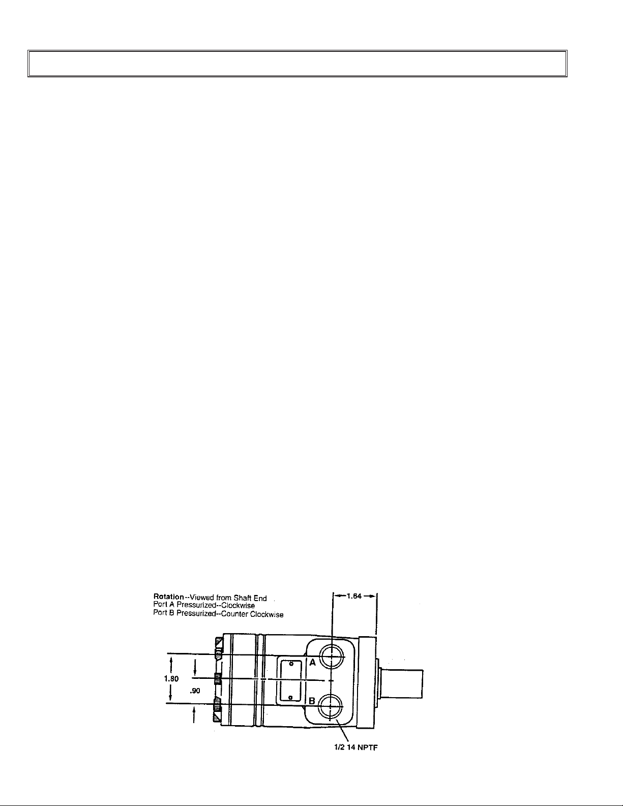
7. Pressure and return hoses,
connected to spinner or auger
motors, may be reversed for proper
motor rotation.
8. Three hose lines to rear of truck
may be installed inside truck frame,
under dump body floor, and secured
in place.
9. Use hose manufacturer's
recommendations for fitting reusable
hose ends.
10. To eliminate hose twisting, allow
hose end clamp to remain loose
until hose end fitting is screwed
tightly in place.
3/4 -1 Wire Hose
3/4 Street Elbow
Pressure Line
From Existing System
3/4 x 1/2
Reducer Bushing
1/2 Street Elbow
Valve 3/4 x 1/2 x 3/4
Elbow
To Tank
1/2-1 Wire Hose
1
JIC (Flared)
NPT (Pipe Thread) ORB (O-Ring)
Requires pipe
thread sealant Self Sealing

9
• This diagram is Monroe Truck Equipment Company's complete recommended hydraulic system.
• Standard pump, valve, tank and hose kits make up the complete system.
• This diagram may be used to install an entire system, or part of a system, depending upon kits supplied, and
existing components on truck.
• Alternate proven methods and components are acceptable to suit various truck model requirements.
1/2-1 Wire Hose 1/2 Quick
Disconnect
1/2-1 Wire Hose
1/2 Street Elbow
Cylinder
1/4 Needle Valve
1/4 Close Nipple
1/2 x 1/4
Reducer Bushing
Relief Valve
(500 PSI)
"IN" Port
1/2 Tee
From Valve
1/2 Close
Nipple
Hydraulic
Motor
1/2 Elbow
1/2 x 3 Nipple To Tank
Required If Not Using
A Motor Spool Valve
1/4-1 Wire Hose
1/2 Street Elbow
Hydraulic
Motor
1/2 x 3 Nipple
1/2 Elbow
1/2-1 Wire Hose
1/2 Quick
Disconnect
1/2-1 Wire Hose

10
I STALLATIO I STRUCTIO S
Reservoir and Filter Installation:
1. Locate the reservoir as close to the pump as possible.
2. The reservoir should be located outside the truck frame. (Ease in filling reservoir is
important.)
3. The integral tank mounting brackets should be bolted to the truck frame.
4. The filter is screwed directly onto reservoir with cartridge down.
5. Oil must flow through filter in direction of arrow on filter.
6. Screw the gauge into the filter and be sure to tighten the plug in the other gauge port.
Valve Installation:
1. Locate valve in truck cab in position convenient for driver and for hosing or piping through
floorboard.
2. Make a 4” hole thru the floor with a 4” hole saw. Position the valve mounting pedestal over
the hole and bolt in place. Push the three (3) proper length hoses with swivel ends up thru
the pedestal. Screw each one into the proper port. “P” is pressure line from the pump; “A”
is the line to the auger; and “T” goes to the tank.
Tie hoses up so they don’t rub the sharp edges of the hole.
3. Bolt the valve in place.
4. The valve may be operated in any position desired.
Hose Installation:
Enough hose and fittings are furnished in the various kits for standard spreader installation. Refer
to the complete hydraulic plumbing diagram included in this manual for hosing all mounted
components.

11
I STALLATIO I STRUCTIO S
IMPORTA T: A pipe joint sealant compatible with
hydraulic oil must be applied to all screwed fittings.
(Teflon tape sealant is not recommended)
CAUTIO : Over tightening fittings in valve may
cause damage to valve body.
Fittings show in solid lines indicate permanent
positions.
1. Screw 3⁄4” street elbow into port #1 until one complete revolution from position shown dotted
cannot be completed. Leave the fitting in this dotted position until further instruction.
2. Screw 3⁄4” street elbow into port #2 using the same procedure as the fitting in port #1 until it
is in position as shown dotted. See further instructions.
3. Finish tightening 3/4” street elbows into ports #1 and #2 until they are in permanent positions
as shown.
4. Screw 3⁄4” x 3” pipe nipple into port #4. Screw 3⁄4” elbow onto nipple and tighten both
fittings together until they are in permanent position as shown.

12
OPERATI G I STRUCTIO S
Caution:
1. Be sure valve is moved completely to “OFF” position and truck engine is shut off before
working on or round spreader equipment!
2. When starting up new equipment, be sure everyone is standing clear and watch for any
thing out of the ordinary that may require shutting the system down.
Initial Test Run:
1. The unit should be ran without material to check operation.
2. Fill the oil reservoir to without about 2” from the top, or to oil level check plug, with a high
grade of non-foaming hydraulic oil. KEEP OIL CLEAN!
3. Move “On-Off” lever on control valve to the “Off” position.
4. Start the engine, engage the PTO or turn on hydrauli system, and allow the oil to circulate
through the system.
5. Open the knob on the control valve and move the “On-Off” lever to the “On” position. If the
engine lugs down, shut the valve “OFF” immediately. This indicates the sytem is not
plumbed properly, which must be corrected.
6. Check the feed roll to make sure it is turning in the right direction. It discharges the
material out the rear of the trough.
7. Check the system for leaks.
8. Refill the reservoir and the system is ready to use.
Preparing Spreader for Use:
1. Start truck engine, engage hydraulic system, turn “On-Off” lever “On” and adjust knob to
vary feed roll speed. Run system to make sure spreader is operating correctly and to warm
up the oil.
2. Shut system off and turn engine off.
3. Position cover plate in vertical poisition and lock cover into place.
4. Adjust back gate opening as required. See adjusting method page.
5. Open dump body tailgate latch and adjust stop chains so tailgate stops just short of the
spreader cover plate.
6. The truck is now ready to load for spreading operation.

13
7. Engage PTO or turn “ON” the hydraulic system.
8. Raise dump body until material slides back and charges the spreader.
9. Set control valve knob to desired setting and engage spreader by moving “On-Off” lever to
“On”.
Spreader Features:
1. The knob that changes the speed of the feed roll may be changed at any time, while the
truck is in motion.
2. The roll may be stopped, without changing vlave setting, by moving the “On-Off” lever to
the “Off” position. This can also be done while the truck is in motion.
3. The back gate is spring loaded in order to pass slightly larger objects thqan the gate
opening. The gate will return to its pre-set poisition after the object has passed.
4. For normal use of the dump truck, the cover plate can be laid flat over the trough. In this
position, the tailgate can be opened from the top or bottom and the load can be dumped
over the spreader.
5. If you have the optional chipping attachment, it should be removed before using the truck
for hauling so it doesn’t get damaged.
Preparing Spreader for Clean-Up:
1. If you have partial load left in the box when you’re done spreading, the hinged feature on
the rear cover plate really helps you. With the body down, just simply unlatch the cover
plate from the vertical-spread position and tip it back towards you. Note that the left end of
the cover plate is notched out. This allows you to push the cover plate over into the
notched area until the right hinge comes out of its hole. It’s eavy-SO BE CAREFU! At
this point, pick the cover plate up and set it on the ground in a safe place.
2. Unhook the chains and dump the load over the spreader.
3. Put the box down and re-hook the tailgate chains so they don’t hang in the trough.
4. MAKE SURE EVERONE IS STANDING CLEAR. Engage the hydraulics; put the “On-Off”
lever in the “On” position. This will turn the feed roll and clear the material out of the
trough.
5. Re-Install the cover plate and the unit is now ready to wash up. The spreader trough
should be kept empty to prevent material from freezing around the roller in severe, cold
OPERATI G I STRUCTIO S

14
weather.
Good Spreader Maintenance:
1. Keep the reservoir full - to check level plug or 2” from top.
2. Replace the oil filter cartridge twice a year or more often if necessary.
3. Clean quick disconnect before taking apart or connecting.
4. All bearings require periodic greasing and more frequent greasing during periods of
heavy use.
5. Grease u-joints and slip shaft on pump drive shaft each time the truck chassis is
lubricated.
6. Roller chains should be checked frequently, cleaned, greased, and the excessive
slack taken up.
7. Frequent greasing or oiling of the spinner hinge rods is suggested.
8. osing down and cleaning the spreader after each use, and repainting or oiling after
each season, will greatly prolong the life of a spreader.
OPERATI G I STRUCTIO S

15
GE ERAL I FORMATIO
• Location descriptions are noted in direction of travel. (i.e. front, rear,
left and right.)
• Delivery of replacement parts is subject to our sales delivery terms.
• Use only Monroe Truck Equipment O.E.M. replacement parts. Failure
to do so will void warranty.
• Replacement parts listed in this manual reflect our most common
items. If you do not find the part you require, please
call your distributor.
•Monroe Truck Equipment reserves the right to make revisions or
alterations to this parts manual.
TORQUE CHART

16
TROUGH ASSEMBLIES
Item Qty Part umber Description
1 1
00068064-A
00068064-B Trough Assembly, MS88RS, MS
Trough Assembly, MS88RS, 304 SST
00068096-A
00068096-B Trough Assembly, MS88RS-DD, MS
Trough Assembly, MS88RS-DD, 304 SST
00075508-A
00075508-B Trough Assembly, MS88RS-GB, MS
Trough Assembly, MS88RS-GB, 304 SST
00041905-A
00041905-B Trough Assembly, MS96RS, MS
Trough Assembly, MS96RS, 304 SST
00068097-A
00068097-B Trough Assembly, MS96RS-DD, MS
Trough Assembly, MS96RS-DD, 304 SST
00075509-A
00075509-B Trough Assembly, MS96RS-GB, MS
Trough Assembly, MS96RS-GB, 304 SST

17
88.75"
00057860 LID WELDME T, MS88-RS, 88.75” (SHOW )
00023200 LID WELDME T, MS96-RS, 96.75”
00057867 ROLLER WELDME T, MS88-RS
00075515 ROLLER WELDME T, MS88-RS-GB
01161125 ROLLER WELDME T, MS96-RS
00075516 ROLLER WELDME T, MS96-RS-GB
00075512 ROLLER WELDME T, MS96-RS-DD
C AIN
GEARBOX
DIRECT DRIVE

00068094 GATE KIT, HYDRAULIC, MS88-RS
Item Qty Part umber Description
1 1 00024914-A
00024914-B Cylinder Assembly, ydraulic, MS
Cylinder Assembly, ydraulic, SST
2 1 00023241-A
00023241-B Adjuster Weldment, Gate, MS
Adjuster Weldment, Gate, SST
3 1 00047033-A
00047033-B Wearstrip, Gate, MS
Wearstrip, Gate, SST
4 1 00057852-A
00057852-B Strip, Seal, ydraulic, MS
Strip, Seal, ydraulic, SST
5 1 00068060-A
00068060-B Retainer, Sealstrip, MS
Retainer, Sealstrip, SST
6 1 00041064-A
00041064-B Wearstrip, Front, MS
Wearstrip, Front, SST
7 1 00075519 Rubber, 5⁄16 x 6 x 87
8 1 05016975 Eyebolt, 1⁄4-20 x 4, Zinc
Hardwar for
Attaching Front
W arstrip It m #6
10
10
10
10
10
10
10
10
05013986
05016003
05020266
05020842
05021365
05021392
05021307
05021390
Bolt, 3⁄8-16 x 1, Carriage, Zinc
Bolt, 3⁄8-16 x 1, Carriage, SST
Nut, 3⁄8-16, ex, Zinc
Nut, 3⁄8-16, ex,SST
Washer, 3⁄8, Lock, Zinc
Washer, 3⁄8, Lock, SST
Washer, 3⁄8, Flat, Zinc
Washer, 3⁄8, Flat, SST
Hardwar for
Installing Gat
Adjust r W ldm nt
It m #2
1
1
1
1
1
4
4
2
2
05035066
05010691
05016096
05020847
05020908
05020268
05020848
05021309
05021391
Spring, Gate, 1.095 x .148 x 5
Bolt, 1⁄2-13 x 11⁄2, Zinc
Bolt, 1⁄2-13 x 11⁄2, SST
Nut, 1⁄2-13, Top Lock, C&W
Nut, 1⁄2-13, Nylon Lock, SST
Nut, 1⁄2-13, ex, Zinc
Nut, 1⁄2-13, ex, SST
Washer, 1⁄2, Flat, Zinc
Washer, 1⁄2, Flat, SST
Hardwar for
Attaching Gat
W arstrip It m #3
and Hydrualic S al
Strip It m #4
12
12
12
12
12
12
05010644
05016049
05020266
05020842
05021365
05021392
Bolt, 3⁄8-16 x 11⁄4, G8, CS, Zinc
Bolt, 3⁄8-16 x 11⁄4, CS, SST
Nut, 3⁄8-16, ex, Zinc
Nut, 3⁄8-16, ex, SST
Washer, 3⁄8, Lock, Zinc
Washer, 3⁄8, Lock, SST
Hardware for
Attaching Sealstrip
Retainer Item #5 and
Rubber Item #7
11
11
11
11
11
05010647
05020266
05020842
05021365
05021392
Bolt, 3⁄8-16 x 2, G8, CS, Zinc
Bolt, 3⁄8-16 x 2, CS, SST
Nut, 3⁄8-16, ex, Zinc
Nut, 3⁄8-16, ex, SST
Washer, 3⁄8, Lock, Zinc
Washer, 3⁄8, Lock, SST
Hardwar for
Attaching Hydraulic
Cylind r Ass mbly
It m #1 and Ey bolt
It m #8
1
1
4
4
2
2
4
4
4
4
05035045
05022161
05010643
05016034
05020264
05020844
05020266
05020842
05021365
05021392
Spring, D Extension
Clevis, Pin Kit, 1⁄2-13
Bolt, 3⁄8-16 x 1, CS, Zinc
Bolt, 3⁄8-16 x 1, CS, SST
Nut, 1⁄4-20, ex, Zinc
Nut, 1⁄4-20, ex, SST
Nut, 3⁄8-16, ex, Zinc
Nut, 3⁄8-16, ex, SST
Washer, 3⁄8, Lock, Zinc
Washer, 3⁄8, Lock, SST
This manual suits for next models
1
Table of contents
Other Monroe Spreader manuals