Shindaiwa HomePro 41RS Broadcast User manual

OWNER’S MANUAL
TM
41RS
BROADCAST

ASSEMBLY
Remove the spreader and com-1.
ponents from the carton. Turn
spreader upside down. Insert (2)
1/4-20 x 1 1/2” hex bolts through
the attened end of handle brace,
frame and leg as shown. Install hex
nuts but do not tighten. Repeat on
opposite side. Make sure braces
are parallel and tighten all nuts.
Slide wheels onto axle with2.
the longer portion of the wheel
facing the frame. The wheels
are identical to ease assembly.
Secure free turning wheel with
(1) 1/8 x 1” cotter pin and (1)
5/32 x 2” cotter pin on the drive
wheel.
Turn spreader upright and3.
install handle tube between
braces. Secure with (2) 1/4-
20 x 2” hex bolts and nuts.
Tighten handle brace nuts
installed in step 1.
VIEWED FROM REAR OF SPREADER
1/4-20 x 1 1/2”
Hex Bolt
Frame Leg
Handle Brace
5/32 x 2”
Cotter Pin 1/8 x 1”
Cotter Pin
Free Turning
Wheel
Drive
Wheel
1/4-20 x 2”
Hex Bolt
Handle Tube
1/4-20 Hex
Nut
1/4-20
Hex
Nut

Feed control knob/wire through4.
the T-handle until spring touches
the round hole. CAUTION: Do Not
Compress Spring At This Time.
Feed wire through the square
handle tube. Be sure wire passes
above the bolts in the handle
brace. Secure T-handle to the tube
with (1) 1/4-20 x 2” hex bolt. (2)
washers, and (1) hex nut in the
bottom hole, and (1) 1/4-20 x 2
1/4” hex bolt, (2) washers, and (1)
hex nut in the top hole as shown.
Remove caution label and push
the thumb release toward the
center and push down knob and
shutoff spring until knob latches.
CAUTION: ONCE KNOB IS LATCHED, DO
NOT MOVE THUMB RELEASE UNTIL YOU
HAVE COMPLETED STEP #5.
Slide wire retaining clip onto5.
wire as shown. Insert wire
through hole shutoff plate. Slide
wire retaining clip over shutoff
plate and wire until the clip
locks into place.
Install gear cover assembly over gears6.
and secure with (2) #6-32 screws. The
41RS spreader should now be com-
pletely assembled and ready for use.
Slide handle grips onto handle. Soapy
water will ease installation. (Do not use
petroleum based products.)
Handle Grip
Remove Caution
Label
Control Knob &
Wire Assembly
Spring
Thumb
Release
1/4-20 x
2 1/4” Bolt &
Washer
1/4-20 Hex Nut
& Washer
Wire Clip
Wire
Shutoff Plate
Handle Grip
#6-32 Screw #6-32 Screw

OPERATION
Check the product package for the rate1.
setting, and recommended swath width. Turn
the spreader off by pushing the control knob
in. Rotate the rate cam to the proper setting.
Always ll the spreader on the driveway 2.
or sidewalk-not on the lawn. Make sure
spreader is in the “OFF” position. Empty
after each use.
Start spreader moving, then open 3.
spreader by pushing the thumb release to
the “ON” position. Always push spreader,
never pull. Push knob down to close
spreader.
Hold handle so top of spreader is level.4.
Tipping the spreader too far can cause
uneven spreading.
The settings and swath widths on the product5.
label are recommended starting points. Always
check the delivery rate and pattern on a small
area before treating a large area. Actual deliv-
ery rate can vary due to weather conditions,
operating variables, and condition of the product
being applied. See “HOW TO DETERMINE
SPREADER SETTING AND SWATH WIDTH”
for details.
Push spreader 3 1/2 m.p.h. (26 feet in 56.
seconds) for full 8’ to 10’ spread pattern
when applying fertilizer products. Apply
header strips at each end of area to be
treated then space trips across the area
as shown.
Push spreader at 2 1/2 mph (18 feet in 57.
seconds) to reduce width of spread when
applying ice melt products to sidewalks.
Empty spreader after each use. Return8.
leftover material to its original container.

HOW TO DETERMINE SPREADER
SETTINGS AND SPREAD WIDTH
EFFECTIVE PATTERN WIDTH
APPLICATION RATE
Two major factors should be considered when determining correct spreader settings of
any product:
The product application rate, or the amount of material applied per 1,000 square feet. 1.
The effective pattern width, or the actual width in which material is applied. Label set-2.
tings are a guide and can be affected by numerous factors.
A simple visual pattern test can be made
by operating the spreader over a non-
turf area and evaluating the pattern. A
more accurate method is to place a row
of common, disposable, aluminum cake
pans approximately 1 foot on centers.
Set the rate cam at a middle setting and
make 3 or 4 passes in the same direc-
tion as shown. Pour the material collected
from each pan into individual bottles of
the same size. Set them side by side in
order, and visually inspect their volume.
The effective pattern width is the distance
out from the spreader to a point where
the amount of material is 1/2 the average
amount in the center pans. This distance
is multiplied by 2 to achieve the total
effective pattern width.
Knowing the effective pattern width (for exam-
ple, 10 feet), measure a distance equal to 100
square feet (10’ x 10’ swath width). Determine
the product coverage is pounds/ 100 sq. ft. by
the recommended square foot coverage (add
two zeroes to the weight of the bag).
EXAMPLE: Product weight: 25 lbs. sq. ft.
coverage: 5,000 sq. ft. 2500 lbs. - 5,000
sq. ft. = .5 lbs. / 100 sq. ft.
Weigh out between 15 to 20 lbs. of material
and spread over the 100 sq. ft. area. Weigh
remaining material left in hopper and adjust
rate setting as required. Repeat test until
application rate is correct.
Space Pan 1’0” on Centers Space for Wheel Track

RATE SETTING CONVERSION
The following provides approximate 41RS settings for those units listed.
The following provides approximate 41RS settings when only the product weight,
square foot coverage, and visual inspection of the material is available.
Conversions should be used as guidelines for establishing proper rate settings. To obtain the
most accurate application rate, follow the procedures described in the Effective Pattern Width
and Application Rate sections. The settings shown here are only approximations and will vary
due to physical characteristics of the product, walking speed, turf condition, humidity, etc. War-
ranty and guarantees of actual coverage or uniformity are neither expressed nor implied.
Shindaiwa
41RSSetting 234567891011 12 13 14 15 16 17 18
Scott Speedy
Green Setting 234567891011 12 13 14 15 16 17 18
Prizelawn
BF1 / BF1SS
Setting
E I K M O R W Z — — — — — — — — —
Lesco
#029600 D — H — K M Q S — — — — — — — — —
Scotts R8A/
SR-1 Setting G K M O Q T — Z — — — — — — — — —
Earthway
2200/2400
Setting
10 — 15 17 19 22 26 30 — — — — — — — — —
Spyker 76/78-2
Setting 4 — 5 6 7 8 9 10 — — — — — — — — —
FERTILIZER
PARTICLE SIZE
BAG RATE
Pounds of fertilizer used per
1,000 sq. ft. of coverage
APPROX.
SETTING
SPREAD
WIDTH
Large, heavy
particles
5
10
15
3 1/2
4
4 1/2
8
8
8
Medium-mixed
particles
5
10
15
2 1/2
3 1/2
4
8
8
8
Small particles
(nitrogen)
1
2
3
2
2 1/2
3
8
8
8
Mixed size particles-
some nes
5
10
15
3
3 1/2
4
6
6
6
Light weight particles
5
10
15
2
2 1/2
3
4
To
6

MAINTENANCE
WARRANTY
Never store unused material in spreader.1.
Return unused product to its original container.
Wash spreader thoroughly after each use2.
and dry completely in sun or heated area.
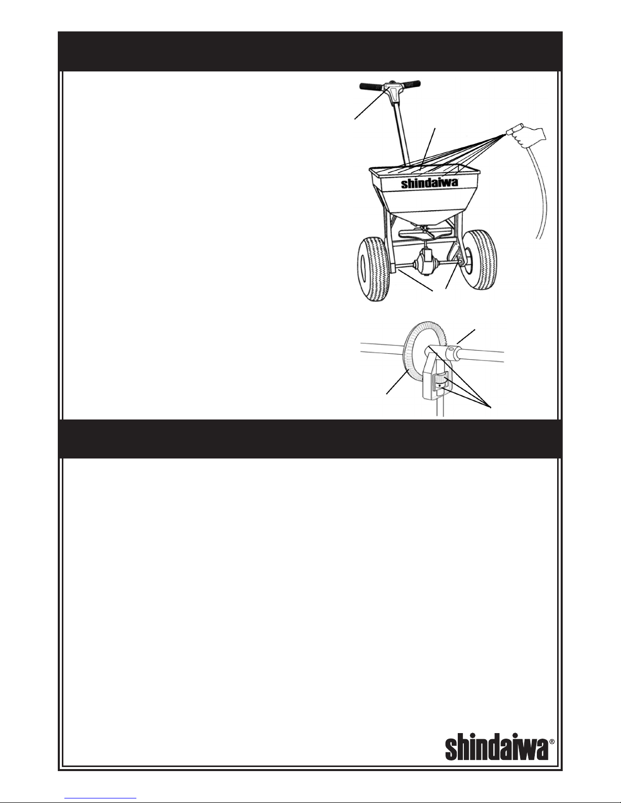
Oil the axle bearings, impeller shaft bearing 3.
in hopper, control knob in T-handle.
Remove gear cover and wash gears4.
thoroughly. Oil all bearing areas and face
of gear teeth. Re-install gear cover.
Gear mesh should be checked on a regular5.
basis during high use periods. Clearance
between the axle gear and pinion gear should
be minimal but not tight. If adjustment is nec-
essary, loosen axle collar set screw and hold
gears together. Slide axle collar against the
gear support and tighten axle collar set screw.
Spin drive wheel. Gears should run freely and
smoothly.
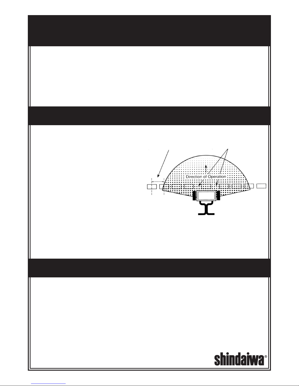
Impeller surface should be cleaned periodically6.
to remove build-up of product. Build-up can
cause the spread pattern to change.
Tire pressure should be 20-25 PSI.7.
Shindaiwa Inc. manufactures its products to superior standards of quality to ensure customers obtain the highest level of satisfaction. In
keeping with this goal, Shindaiwa Inc. warrants the unit to the original purchaser as follows:
WARRANTY PERIOD
One year from the delivery date to the original purchaser for consumer and commercial applications.90 days for rental applications.
WARRANTY ADMINISTRATION
Within the covered warranty period, Shindaiwa Inc. will, at their option, repair or replace any defect in material or workmanship, without
charge for parts or labor, if this product is presented at an authorized Shindaiwa dealer.
WARRANTY EXCLUSIONS AND LIMITATIONS
Shindaiwa Inc. assumes no responsibility for damages, loss, or injury resulting from:
Normal wear and tear
Misuse or neglect
Modications to or removal of original component parts
The warranty is limited to the terms stated herein. Shindaiwa Inc. disclaims all liability for incidental or consequential damages. Some
states do not allow the exclusion of incidental or consequential damages, so these limitations may not apply to you.
This warranty give you specic legal rights, and you may also have other rights which may vary from state to state.
Shindaiwa reserves the right to change the design or specications of this product without obligation to modify previously manufactured
products.
OWNER’S RESPONSIBILITIES
The owner of the unit must demonstrate reasonable care in the use, maintenance, and storage of this Shindaiwa product. If a warrant-
able failure should occur, the owner must deliver the product to an authorized Shindaiwa servicing dealer for correction. All residual chem-
icals must be ushed from the tank prior to delivery.
Unidentied chemicals left in the tank can pose a serious health threat to anyone servicing the unit and unaware of its
presence!
To obtain warranty service, proof of purchase must be presented to the authorized Shindaiwa servicing dealer when the product is
presented for repairs.
Proof of purchase must include date of purchase and the name and address of the selling dealer.
Oil
Oil Impeller Shaft
Bearing In Hopper
Oil Oil
Axle Collar

Parts List for SHINDAIWA MODEL 41RS
PART OF OUR SERVICE IS PRO-
VIDING REPLACEMENT PARTS.
Parts may be obtained through your
local distributor. be sure to give:
SPREADER MODEL NUMBER1.
SPREADER NAME2.
PART NUMBER3.
NAME OF PART AS SHOWN4.
11975 SW Herman Rd.
Tualatin, Or. 97062
503-692-3070 Fax 503-692-6696
www.shindaiwa. com
P / N 82010
23
15
14
22
21
12
6
16
17 18
19
1
10
3 2
5 13
4
13
20
7 9
8
11
Key
No.
Description Part No. Key
No.
Description Part No.
1 Hopper Ass’y-includes #2 & 3 15845 13 Drive & Free Turning Wheel 14939-1
2 Rate Cam & Chute Assembly 14455-1 14 Handle Braces (2) 13613-1
3 Shutoff Plate 14454-1 15 Handle Tube 14513-1
4 Impeller Assembly 15849 16 T-Handle Assembly 13634-2
5 Frame Assembly 15837 17 Control Knob Spring 14462
6 Legs (2) 13619-1 18 Control Knob & Wire Ass’y 13640-1
7 Axle 15842 19 Wire Retaining Clip 13643-1
8 Axle Collar 13362 20 Gear Cover Assembly 13623-1
9 Axle Bushings (2) 12696 21 Fastener Package 15880
10 Impeller Shaft Bearing 15833 22 Hopper Cover 15209
11 Axle Gear 13625-1 23 Handle Grip (2) 15264
12 Agitator 15866
This manual suits for next models
1
Table of contents
Other Shindaiwa Spreader manuals

Shindaiwa
Shindaiwa HomePro 76RS User manual

Shindaiwa
Shindaiwa RS76 User manual

Shindaiwa
Shindaiwa RS60 Instruction Manual

Shindaiwa
Shindaiwa RS41 Instruction Manual

Shindaiwa
Shindaiwa RS600 User manual

Shindaiwa
Shindaiwa RS41 User manual

Shindaiwa
Shindaiwa RS60 User manual

Shindaiwa
Shindaiwa RS850/S User manual

Shindaiwa
Shindaiwa RS76 User manual

Shindaiwa
Shindaiwa RS600 User manual