10.
IMPORTANT HEALTH & SAFETY INFORMATION
1. WARNING
FOR OUTDOOR USE ONLY! DO NOT USE INDOORS
Please read these instructions carefully prior to assembly and use.
Failure to follow these instructions could lead to serious injury and/or significant damage to property.
Do not start the barbeque if there is any doubt over the correct assembly, ignition, gas control or cooking of the unit.
These instructions should be retained for future reference.
For use with ULPG cylinder gas only.
The barbeque must have a minimum side clearance from any combustible material of at least 250mm. Additionally there must be a clearance of at least
1500mm above the cooking surface of the barbeque, 500mm clearance at the back.
Flammable materials and liquids must be stored well away from the barbeque.
Aerosols must not be used near the barbeque.
The barbeque should not be moved when lit or hot.
A lit barbeque should be attended at all times.
Gas cylinders MUST be stored vertically.
Avoid dousing the barbeque with water.
Turn off the gas cylinder when the barbeque is not in use.
Always allow the barbeque to completely cool down before covering.
For safety reasons it is advisable to keep a fire extinguisher and fire blanket close to hand.
Unsupervised children, elderly and infirm should not be allowed close to the barbeque during pre-heat, cooking, burn off or cooling down of the unit.
Please dispose of all polythene packing and plastic bags carefully and keep out of the reach of children.
2. GAS TYPE AND REGULATOR
This barbeque is only designed to run off ULPG cylinder gas.
To ensure maximum performance a gas cylinder of 9kg is recommended.
•The regulator as supplied should be firmly tightened but care must be taken not to over-tighten the connections.
The regulator as supplied is the correct regulator for this item.
Do not attempt to connect gas to a barbeque that is not secure in a frame or trolley.
To ensure performance a gas cylinder of minimum 4.5kg is required.
3. IF YOU SMELL GAS
DO NOT ATTEMPT TO OPERATE THE BARBEQUE UNTIL THE CAUSE
OF THE GAS SMELL HAS BEEN IDENTIFIED AND ELIMINATED.
Immediately isolate the gas supply by turning the gas off at the cylinder.
Extinguish all naked flames.
Do not operate any electrical devices close to the barbeque.
Check for leaks as described further in this manual.
Ensure that local area is well ventilated to remove any excess gas.
If the gas smell continues the barbeque should not be operated under any circumstances and it is important to make immediate contact
with the customer service centre.
4. PRECAUTIONS
BEFORE FIRST TIME OPERATION AND AFTER EACH CYLINDER EXCHANGE/REFILL
ALL CONNECTIONS SHOULD BE CHECKED FOR GAS LEAKS.
Connections can be checked for leaks by using a soapy water solution.
Naked flames (matches or other open flames) must not be used to check for gas leaks, this is a dangerous practice to be avoided.
Flammable liquids of any description, including petrol, lighter fluid, oils, etc must not be stored close to the barbeque.
Spare or extra gas cylinders must NOT be stored within close proximity of this barbeque or any other gas or electric appliance.
Spare or extra gas cylinders should not be stored where they are exposed to continuous direct sunlight, as this is a potentially dangerous practice.
The position of the assembled barbeque should be such that the gas cylinder is not left exposed to direct sunlight as this is a potentially dangerous situation.
Please read and follow all instructions in this manual, if in doubt as to any operational or safety precaution contact the customer service centre.
Please ensure the gas cylinder is positioned outside of the barbeque frame. It must not be positioned underneath the barbeque.
For storage and cylinder exchange, disconnect the cylinder only. Do not disconnect hose from the appliance.
DC3V 1.5VX2 30
29
32
31 33
24
SAFETY
GAUGE
GAS
25
H VIEW
9.
1. Working from the back, slide Oil Cup (24)
into the brackets under the Fat Tray,
as shown in diagram.
1. Prior to fitting gas cylinder ensure the cart, shelves, body and lid are secure.
2. All fixings are tight.
3. Partially loosen bolts in Flexible Gas Hose Fixed (25)
and position over main barbeque gas hose connection
as shown in diagram.
4. Place bolt heads through mounting holes in
Cart Right Panel (5) and push down into correct
position as shown in H View.
Tighten bolts but do not over-tighten.
5. Place gas cylinder on Gas Tank Tray (7);
ensure the gas supply is off.
6. Connect the regulator to the gas cylinder;
7. Care must be taken not to cross-thread these
connections and do not over-tighten the nut.
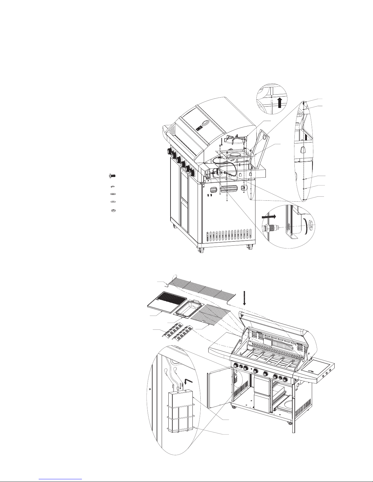
1. Align Motor Sup (30) to pre-drilled left-hand side of Body & Lid Assembly (12) holes as shown in diagram.
2. Thread 2xBolt (A) through Motor Sup (30) and Body & Lid Assembly then through Flat Washers (C)
and Spring Washer (B) into Nuts (M). Tighten.
3. Mount Motor (29) onto Motor Support (30).
4. Connect Fork A (31) and Fork B (32) as shown in diagram.
5. Hang Clump weight (33) from Fork B (32).
6. Insert assembled fork to Motor (29) resting right-hand side on Body & Lid Assembly (12) right side panel.
A M6X12...2 PCS
B M6 SPRING WASHER...2 PCS
C M6 FLAT WASHER...2 PCS
M M6 NUT...2 PCS
STEP 12
PLACEMENT OF OIL CUP
STEP 14
ATTACH FLEXIBLE GAS HOSE FIXED AND CONNECT GAS CYLINDER
THIS IS A LEFT HAND THREAD MEANING IT
TIGHTENS IN AN ANTI-CLOCKWISE DIRECTION.
STEP 13
MOUNT ROTISSERIE