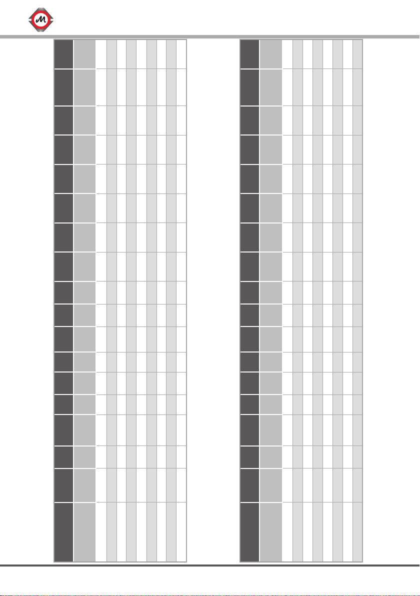
Montanari MGV20 Series User guide

www.montanarigiulio.com
O
18
190
100
200
REV:4_03_2021
MANUALS
MGV20RANGE
INSTALLATION, USE AND MAINTENANCE
GEARLESS

2
DOWNLOAD OUR APP!
A unique container of all documentation available for gearboxes, gearless, speed
governors and safety gears.
You may check your supply, configure the inverter, download manuals, tech
reports, certificates and much more.
Search for Montanari Giulio App, available on Google Play and App store.
SCAN THE QR TO DOWNLOAD
ANDROID APP
SCAN THE QR TO DOWNLOAD
iOS APP

3
www.montanarigiulio.com
MGV20M - L ENGLISH
Thank you for choosing a Montanari product.
Since 1970, Montanari Group has been focused on
providing its customers with the best traction machines and
components for lifts and escalators.
We are proud to have you as a customer and user of the
Montanari traction machines, and we are confident that we
can work together for a long time.
Thanks again for your choice.
Massimo Montanari
CEO of Montanari Group

4
REV. DATE DESCRIPTION EDITED BY VERIFIED BY APPROVED BY
1 20/11/2019 First Redaction Marketing Dept Technical Dept
Alberto Mantovani
STEFANO BERTONI
(DTE)
2 24/03/2020 Technical data update Marketing Dept Technical Dept
Alberto Mantovani
STEFANO BERTONI
(DTE)
3 05/10/2020 Update Marketing Dept Technical Dept
Alberto Mantovani
STEFANO BERTONI
(DTE)
4 02/03/2021 Update Marketing Dept Technical Dept
Alberto Mantovani
STEFANO BERTONI
(DTE)
WARNING SYMBOLS
USED IN THE MANUAL:
TIP
!
!
It indicates that safety measures must
be taken to avoid electric shock.
It indicates that safety measures must
be taken to prevent personal injury.
It indicates that safety measures
must be taken to prevent damage to
components.
It indicates that safety measures must
be taken to prevent burns due to
contact with hot/ overheated surface.
It indicates useful information before
and during the installation step.
It refers to specific parts of the
manual.
It refers to the proper product
disposal.

5
www.montanarigiulio.com
MGV20M - L ENGLISH
CONTENTS
1. GENERAL INFORMATION .....................................................................7
1.1 Introduction............................................................................................7
1.2 Copyright ...............................................................................................7
2. SAFETY...................................................................................................8
2.1 Intended use ..........................................................................................8
2.2 User’s obligations ...................................................................................8
2.3 Correct disposal ...................................................................................9
2.4 Specific hazards......................................................................................9
2.5 Legal References ....................................................................................9
3. IDENTIFICATION AND DATA ................................................................9
3.1 Identification plate .................................................................................9
3.2 Dimensions...........................................................................................12
3.3 Sound pressure.....................................................................................13
4. TRANSPORT AND STORAGE ..............................................................13
4.1 Handling...............................................................................................13
4.2 Storage.................................................................................................14
5. DESCRIPTION ......................................................................................14
5.1 General description..............................................................................14
5.2 Main components ...............................................................................15
5.3 Brake ....................................................................................................17
6. INSTALLATION.....................................................................................18
6.1 General installation information ...........................................................18
6.2 Installation surface................................................................................18
6.3 Installation procedure...........................................................................18
6.4 Electrical installation - Connections .....................................................20
7. CONNECTION OF THE BRAKE FOR RESCUE SYSTEM......................22
7.1 Connection of the cable to the brake levers........................................22
7.2 Connection of the cable to the hand release lever..............................23
7.3 Rescue System .....................................................................................23

6
8. OPERATION .........................................................................................24
8.1 Connections .........................................................................................24
8.2 Additional components........................................................................24
8.3 General operation information.............................................................24
9. TROUBLESHOOTING, MAINTENANCE AND REPAIR ........................24
9.1 General information .............................................................................24
9.2 Traction/return sheave..........................................................................25
9.3 Replacement of components ...............................................................25
9.4 Problems, causes and solutions .........................................................25
9.5 Maintenance and repair .......................................................................26
9.5.1 General indications ...........................................................................26
9.5.2 Description of maintenance activities................................................26
10. SPARE PARTS .......................................................................................27
10.1 General information ...........................................................................27
10.2 How to order spare parts ...................................................................27
11. COMPLIANCE DECLARATION ............................................................28

7
www.montanarigiulio.com
MGV20M - L ENGLISH
1. GENERAL INFORMATION
1.1 Introduction
These operating instructions must always be available for consultation. No
liability is accepted for any malfunction due to installation not conforming to
specifications, except in cases approved by Montanari Giulio & C.
All persons involved in the installation, operation, maintenance and repair of the
unit must have read and understood the instructions.
No liability is accepted for damage, breakage or accident caused by failure to
follow the instructions.
To make technical improvements, Montanari reserves the right, if deemed
necessary, to modify the units and accessories, preserving their essential char-
acteristics and improving efficiency and safety, without notice.
1.2 Copyright
All rights to these operating instructions belong to Montanari Giulio & C. S.r.l.
The information in this manual may not be reproduced or used in an unauthor-
ized manner or made available to third parties without prior approval.
If you have any questions, please contact:
MONTANARI GROUP
HEADQUARTER - MONTANARI GIULIO & C. Srl
Via Bulgaria 39 - 41122 - Modena - Italia
Tel: +39 059 453611 - Fax: +39 059 315890
www.montanarigiulio.com

8
2. SAFETY
2.1 Intended use
The MGV20 gearless machine is supplied ready for safe and reliable use. Any
modification by the user that may affect safety or reliability is prohibited; it is
also prohibited to tamper with devices or functions designed to prevent acci-
dental contact.
The Montanari MGV20 gearless machine must be used and operated
in strict compliance with the conditions set out in the supply contract.
!
Technical specifications considered: speed, cab capacity, cab weight, presence
or absence of compensation, roping at the time of order.
No liability is accepted for any malfunction due to installation not conforming to
specifications, except in cases approved by Montanari Giulio & C.
2.2 User’s obligations
The operator must ensure that all persons involved in installation, operation,
maintenance and repair have read and understood the supplied operating
instructions and have adapted to them in order to:
• Avoid damage to property or persons.
• Ensure safe and reliable operation of the unit.
• Avoid breakage and environmental damage due to misuse.
In particular:
• Always observe the relevant environmental and safety regulations when
transporting, assembling, installing, operating, maintaining and dismantling
the unit.
• The unit must only be used, maintained and repaired by authorized, prop-
erly trained and qualified personnel.
• The gearless must not be cleaned using high-pressure cleaning equipment.
• All work must be carried out with care and with due attention to safety.
• Any work on the unit should only be carried out when it is not in operation.
• A warning must be placed on the main switch to clearly indicate that work
is in progress on the unit.
• No welding must be carried out on the unit.
• Do not use the unit as a grounding point for welding operations.
• If any changes are detected (e.g. overheating or unusual noise) during
operation, switch off immediately.
• Rotating components must be equipped with appropriate guards to pre-
vent contact.
• If the unit is intended for installation in plant or machinery, the manufacturer
of such plant or machinery must ensure that the standards, indications and
descriptions contained in these operating instructions are incorporated into its
own instructions.

9
www.montanarigiulio.com
MGV20M - L ENGLISH
N Norm Description
1 UNI 10147 Maintenance: Terminology.
2 EN 81-20 Safety rules for the construction and installation of lifts - Lifts for the transport of persons
and goods.
3 EN 81-50 Safety rules for the construction and installation of lifts - Examinations and tests.
4 EN 81-21 Safety rules for the construction and installation of lifts - Lifts for the transport of persons
and goods - Part 21: New passenger and goods passenger lifts in existing building.
3. IDENTIFICATION AND DATA
3.1 Identification plate
The data on the plate are:
• The information on the warning or identification plates must be complied
with. These plates must be kept clean and legible at all times. Missing plates
must be replaced.
• All spare parts can be obtained from Montanari Group.
2.3 Correct disposal
Respect the environment and dispose of the product according to the
regulations in force in the country of installation.
2.4 Specific hazards
Depending on the conditions of use, the surface of the unit can become very
hot.
Fig. 1
Danger of burning!
!
Manufacturer
Manufacturer’s
address
Year of production
Serial number
Gearless
machine
code
Model
Speed
Rated
voltage
Frequency
Power rating
Cycle type
Rated torque
Motor
pole no.
Rated current
Weight
QR code to access
the relevant
documentation.
2.5 Legal References Tab. 1
- Example of Identification Plate
Download
App

10
MGV20M Type Pn
Speed Vn Cn In Cmax Imax EMF Poles F Rs Ls Static
Load IDuty
Cycle Weight
Code
machine kW [RPM] [V] [Nm] [A] [Nm] [A] [V∙s/
rad] [N°] [Hz] [Ω] [mH] [Kg] [kg∙m2] [Kg]
MGV20152393B401 MGV20M 1,57 75 210 200 13 340 23 8 20 12,5 2,3 10 3000 0,04 180S/H 40% 125
MGV20152913B401 MGV20M 2,4 115 210 200 14,7 340 26 7 20 19,2 1,7 7,4 3000 0,04 180S/H 40% 125
MGV20153823B401 MGV20M 3,35 160 210 200 17,5 340 31 6 20 26,7 1,2 5,3 3000 0,04 180S/H 40% 125
MGV20155103B401 MGV20M 5 239 210 200 23,5 340 40 4 20 39,8 0,73 3,1 3000 0,04 180S/H 40% 125
MGV20151193B401 MGV20M 2,5 119 360 200 8,5 340 15 13 20 19,8 5,3 23 3000 0,04 180S/H 40% 125
MGV20152393B401 MGV20M 5 239 360 200 13 340 23 8 20 39,8 2,3 10 3000 0,04 180S/H 40% 125
MGV20152913B401 MGV20M 6,09 291 360 200 14,7 340 26 7 20 48,5 1,7 7,4 3000 0,04 180S/H 40% 125
MGV20153823B401 MGV20M 8 382 360 200 17,5 340 31 6 20 63,7 1,2 5,3 3000 0,04 180S/H 40% 125
MGV20155103B401 MGV20M 10,7 510 360 200 23,5 340 40 4 20 85 0,73 3,1 3000 0,04 180S/H 40% 125
MGV20L Type Pn
Speed Vn Cn In Cmax Imax EMF Poles F Rs Ls Static
Load IDuty
Cycle Weight
Code
machine kW [RPM] [V] [Nm] [A] [Nm] [A] [V∙s/
rad] [N°] [Hz] [Ω] [mH] [Kg] [kg∙m2] [Kg]
MGV20202553B501 MGV20L 1,9 70 210 265 17 450 31 8 20 11,7 1,7 7,8 3000 0,05 180S/H 40% 145
MGV20203823B501 MGV20L 4,4 160 210 265 23,5 450 42 6 20 26,7 0,9 4,1 3000 0,05 180S/H 40% 145
MGV20205103B501 MGV20L 7,1 255 210 265 31 450 53 5 20 42,5 0,53 2,4 3000 0,05 180S/H 40% 145
MGV20200913B501 MGV20L 2,5 91 360 265 10 450 18 18 20 15,2 5 23 3000 0,05 180S/H 40% 145
MGV20201603B501 MGV20L 4,4 160 360 265 13 450 23 12 20 26,7 3,1 14 3000 0,05 180S/H 40% 145
MGV20202553B501 MGV20L 7,1 255 360 265 17 450 31 8 20 42,5 1,7 7,8 3000 0,05 180S/H 40% 145
MGV20203823B501 MGV20L 10,6 382 360 265 23,5 450 42 6 20 63,7 0,9 4,1 3000 0,05 180S/H 40% 145
MGV20205103B501 MGV20L 14,1 510 360 265 31 450 53 5 20 85 0,53 2,4 3000 0,05 180S/H 40% 145
GEARLESS MACHINE TECHNICAL CHARACTERISTICS: MGV20M - MGV20L
Tab. 2
Tab. 3

11
www.montanarigiulio.com
MGV20M - L ENGLISH
BRAKE CHARACTERISTICS
Model Brake model Power Voltage Current Braking Force Certificate
[W] [V] [A] [Nm]
MGV20M RTW180 2 x 265 W
2 x 67 W
207VDC PK
104V DC HOLD
2 x 1,3 A
2 x 0,65 A 2 x200 Nm EU-BD 954
MGV20L RTW250 2 x 79 W 207VDC 2 x 0,4 A 2 x250 Nm EU-BD 845
Tab. 4

12
3.2 Dimensions
The technical drawing and the overall dimensions follow.
Fig. 2
MGV20M
Fig. 3
MGV20L
148,5
324
200
190
Ø18
100
270
240
D
395,5
Ø
148,5
237
100
200
190
O
18
O
264328,5
324

13
www.montanarigiulio.com
MGV20M - L ENGLISH
3.3 Sound pressure
MGV20 RANGE / Sound pressure in dB(A)*
Version When operating With brake
M≤48 ≤54
L
Only use lifting systems and equipment with adequate lifting capacity
for handling. The entire packaging is designed to allow movement with
forklift and forklift truck.
!
4. TRANSPORT AND STORAGE
4.1 Handling
All gearless machines are packed in crates or cages.
Different types of packaging can be used, depending on the size and means
of transport. Unless otherwise specified, the packaging complies with the HPE
guidelines.
In some cases, the machines are mounted on wooden pallets to enable them
to be transported correctly on trucks. The packaging may not be stacked in any
way. It is recommended to check the conditions of the material when it is re-
ceived. In case of damage, do not proceed with the installation unless expressly
authorized by Montanari Giulio & C. Observe the symbols on the packaging to
prevent damage to property or personal injury. Here are the meanings of the
symbols that may appear on the packaging.
Keep dry Handle with care
Upper side Do not use hooks
Fragile Center of gravity
Keep away from
heat sources
Attachment point
Tab. 5

14
For lifting, anchor points (eye-
bolts) are provided as shown in
Fig. 4.
Use only the specified eyebolts to
handle the unit.
Fig. 4
! !
4.2 Storage
The gearless machine must be stored in the position of use on a wooden base
not subject to vibrations, in a covered and sheltered place.
If the unit is stored outdoors, it should be covered, taking care that no
moisture and/or other foreign matter can accumulate on it.
!
Supplies for special environmental conditions during transport (e.g.
by ship) and storage (climate, temperature, etc.) must be contractually
agreed.
!
• Check the correct operation of the motor and brake after installation.
• Repairs may only be carried out by the manufacturer or by authorised per-
sonnel.
• The machine can be red-hot.
• These machines must be connected to inverters.
• When the machine is rotating, both manually and mechanically, it can act as
a generator and produce high voltage.
• During configuration, the machine is powered by high voltage.
5. DESCRIPTION
5.1 General description
The MGV20 series gearless machines are permanent magnet motors with
double brake system.
! !

15
www.montanarigiulio.com
MGV20M - L ENGLISH
5.2 Main components
The unit consists of the main groups as shown in Fig. 5 - 6
MGV20 M - L are equipped with a PTC thermal probe inside the windings to
protect against overheating (winding temperature up to 130°C) and with a ther-
mo-contact for the activation of the fans. Refer to the electrical connections for
more details. - See Par. 6.4.
Lubrication
The gearless machine contains no oil and it is supplied with bearings
already lubricated throughout the life of the machine; no further lubri-
cation is required.
!
Brake
Standard
guards
Fig. 5
Cooling fans
Traction sheave
Fixing holes
Motor cable
outlet
Label
MGV20M
Standard guards
Fig. 6
Cooling fan
Pulley
Fixing holes
Motor cable
outlet
MGV20M Brake detail
Encoder
Brake electromagnet
Brake Disk
Microswitch
brake
Brake levers

16
Standard
guards
Fig. 6
Cooling fan
Pulley
Fixing holes
Motor cable
outlet
Brake levers
MGV20L
Brake detail
Encoder
Brake electromagnet
Brake Disk
Microswitch
brake
Brake
Standard
guards
Fig. 5
Cooling fans
Traction sheave
Fixing holes
Motor cable
outlet
Label
MGV20L

17
www.montanarigiulio.com
MGV20M - L ENGLISH
5.3 Brake
The gearless machine is supplied with a brake that conforms to the standards
indicated in paragraph 2.5.
The brake system is pre-calibrated by the manufacturer and no further adjustment
is required.
The brake system operates as follows:
• Not powered (electromagnet not powered): the brake disc is clamped
by the movable surfaces (yellow arrows on Fig. 7). In this condition the system
does not move.
• When the brake electromagnet is powered, it releases the brake disc
(yellow arrows in Fig. 8); now the motor is released.
!!
AIR GAP 0,5 mm AIR GAP 0 mm
Brake system not powered Brake system powered
Fig. 7 Fig. 8

18
6. INSTALLATION
6.1 General installation information
The gearless machine must be installed in a building or in a closed travel com-
partment.
Do not use the gearless machine in an explosive atmosphere.
The room temperature must be between 0°C and +40°C.
Assembly and installation must be carried out with great care by qualified and
trained personnel.
The manufacturer cannot be held responsible for damage caused by incorrect
assembly or incorrect installation.
Before starting work, make sure that adequate lifting and handling equipment
is available.
No welding work must be carried out on the unit.
The unit must not be used as a grounding point for welding operations. The
bearings can be irreparably damaged.
All fixing points specified by the manufacturer must be used.
The air supply for cooling must not be prevented.
6.2 Installation surface
The installation surface must be uniform and level.
The levelling tolerance is 0.1 mm.
The installation surface must be rigid and robust enough to withstand the forces
involved.
6.3 Installation procedure
The gearless machine can be lifted using the eyebolts for the insertion of the
belts or lifting chains (see also the paragraph on storage and handling). Particu-
lar attention is needed to avoid that the gearless machine receives blows in cor-
respondence of the brake disc; the brake levers and the electrical connections
of the board are very delicate. Lifting example Fig. 9.
!!
Fig. 9

19
www.montanarigiulio.com
MGV20M - L ENGLISH
Place the unit on the installation surface and secure it.
• Fixing screws and nuts must be tightened to the prescribed torque.
• Use bolts with a minimum strength class of 8.8.
• Do not force or hit the fixings to position them; this could damage the
bearings, rings, etc.
• Mount the safety devices.
N.B.: Tight correctly the eyebolts.
The static load changes depending on the roping direction. (Fig. 10):
Fig. 10
LATERAL
DOWNWARDS
STATIC LOAD:
3.000 kg
STATIC LOAD:
1.500 kg
STATIC LOAD:
1.200 kg
UPWARDS
Load direction

20
!!
Brake disc closed Condition
contact Brake disc free Condition
contact
Disconnected Connected
Connected Disconnected
BLACK
COM.
BLUE
N.O.
BLACK
COM.
GREY
N.C. COM. N.C.
BLACK
COM.
BLUE
N.O.
Fig. 11
Shielding cable
(Grey)
Grounding
(Yellow green) Power cables for
the U-V-W phases
(1 - 2 - 3)
• The power cable must be routed separately from the other cables.
• The motor power cable is shielded and the shield must be grounded.
• The encoder cable must be routed away from the motor power cable to avoid
electrical interference.
• The brake system has a power cable and another cable for the microswitch
contacts. (Fig. 12). All electrical data are listed on the label of the brake system.
The microswitch has two contacts: one open and one closed. (Fig. 13).
• These contacts indicate the brake condition (see Tab. 7).
Tab. 7
Cables for PTC probe
PTC (T5 - T6)
Cooling fans cables
(F7 - F8) [230Vac]
Cable
6.4 Electrical installation - Connections
The gearless machine is supplied with:
• Cable for the power supply of the motor [1 - 2 - 3, Ground, SC] (Fig. 11), for
the power supply of the cooling fan (230 Vac) [F7-F8] and of the PTC [T5-T6] (Fig.
11).
BLACK GREY
This manual suits for next models
12
Table of contents
Other Montanari Engine manuals
Popular Engine manuals by other brands

Briggs & Stratton
Briggs & Stratton 402500 Series Illustrated parts list

Robin
Robin EY15 Service manual

Ametek
Ametek dunkermotoren BG 65 dMove Series Translation of the original function and connection guide

Bosch
Bosch Hagglunds CB Installation and maintenance manual

Rotax
Rotax 912 Series installation manual

Cub Cadet
Cub Cadet 195 cc OHV Operator's manual