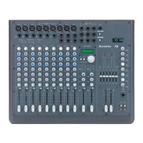
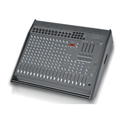
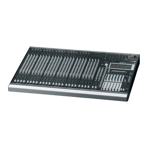
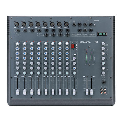
Montarbo 783 User manual


783
/
784 professional audio mixing systems
IMPORTANT ! Safety instructions
CONTENTS
Section 1: installation and care
Section 2
◗2.1 Introduction
◗2.2 MONO input module
◗2.3 STEREO input module
◗2.4 EFFECTS module
◗2.5 MASTER module
◗2.6 External power supply unit
Section 3
◗3.1 Initial set-up
◗3.2 Suggestions for better operation
◗3.3 In case of problems…
Section 4: connections
◗4.1 Live
◗4.2 4-track recording
◗4.3 Master and monitor outputs
◗4.4 External effects
◗4.5 Stereo tape recorder
Section 5
◗5.1 Block diagram
◗5.2 Technical specifications
3
4
5 - 9
10 - 14
15 - 17
18 - 27
28
29
29
30
31 - 32
33
34
35
35
36
37
The lighting flash with arrowhead symbol within an equilateral triangle, is
intended to alert the user to the presence of uninsulated "dangerous voltage"
within the product's enclosure, that may be of sufficient magnitude to constitute
a risk of electric shock to humans.
The exclamation point within an equilateral triangle, is intended to alert the
user to the presence of important operating and maintenance (servicing)
instructions in the literature accompanying the product.
WARNING !
In order to protect your own and others' safety and to avoid
invalidation of the warranty of this product, please read this
section carefully before operating this product.
-This product has been designed and manufactured for being operated
as mixing console in the applications tipical of a sound reinforcement
system or of a sound recording system. Operation for purposes and in
applications other than these has not been covered by the manufacturer
in the design of the product, and is therefore to be undertaken at end
user's and/or installer's sole risk and responsability.
To avoid the risk of fire and/or electric shock:
•Never expose this product to rain or moisture, never use it in proximity
of water or on a wet surface. Never let any liquid, as well as any object,
enter the product. In case, immediately disconnect it from the mains
supply and refer to servicing before operating it again.
•Before connecting this product to the mains supply, always make
sure that the voltage on the mains outlet corresponds to that stated
on the product.
•This product must be connected only to a grounded mains outlet
complying to the safety regulations in force via the supplied power
cable. In case the power cable needs to be substituted, use exclusively
a cable of the same type and characteristics.
•Never place any object on the power cable. Never lay the power cable
on a walkway where one could trip over it. Never press or pinch it.
•During operation do not cover the mixer and do not keep it in
containers which may prevent correct air circulation.
•In case the external fuse needs replacement, substitute it only with
one of the same type and rating, as stated on the product.
•Always make sure the On/Off switch is in its 'Off' position before
doing any operation on the connections of the product.
•Before attempting to move the product after it has been installed,
remove all the connections.
•To disconnect the power cable of this product from the mains supply
never pull the cable directly. Hold the body of the plug firmly and pull
it gently from the mains supply outlet.
-Before placing the product on a surface of any kind, always make sure
that its shape and load rating will safely match the product's size and
weight.
-To avoid shocks always reserve a protected area with no access to
unqualified personnel as installation site of the product. In case the
product is used near children and animals closest supervision is
necessary.
-This product in combination with headphones or speakers can
generate very high acoustic pressures which are dangerous for the
hearing system. Do not operate for a long period of time at a high
or unconfortable volume level. Never expose children to high sound
sources.
CAUTION !
This product does not contain user serviceable parts.
To prevent fire and/or electrical shock, never remove its cover.
Maintenance and servicing must be carried out the official
Montarbo Distributor in your State or by qualified personnel
specifically authorized by the distributor.
783/784
2

783
/
784 professional audio mixing systems 3
1: Installation and care
■ Both models use a separate power supply.
Never use a different power supply (or an home made
unit): this is likely to cause damage.
■ Connect the power supply to the mixing console
using the supplied multipin cable, and the power supply
to the mains socket using the supplied power cable,
or any suitable three conductor cable conforming to
applicable safety regulations. Be sure that the ground
conductor is connected.
■ Before connecting to mains socket, be sure
that the mains voltage corresponds to the one
indicated on the power supply unit.
■ The power supply unit needs free air circulation
for proper cooling: never cover it in any way during
operation.
■ Always switch off the power supply before
connecting or disconnecting the mixer’s supply cable
or before attempting service to the mixer (in any case
service must be done by qualified personnel only).
■ Before switching on or off the power supply, close
(set to minimum) the output faders.
This will avoid switching noises that may cause damages
to loudspeakers.
■ Always use quality cables and connectors.
Never expose the mixer and the power supply
to heat sources, direct sunlight, excessive
vibrations or mechanical shocks.
Avoid operating and storing the units in damp or
dusty places, and absolutely never expose them
to rain: this will avoid malfunctions, premature
degrading of specifications and the risk of
electrical shocks and fires.
Avoid using the mixer close to strong sources of
electromagnetic interferences (e.g. video monitors,
high power electrical cabling).
This may lead to degradation of audio quality
due to induced voltages in connection cables
and chassis.
For the same reason, always place the power
supply as far as possible from the mixer.
Care should be taken so that objects do not fall
and liquids are not spilled into the mixer.
In pubblic event don't let people, musicians,
technicians or anyone put glasses, cups, ashtrays
and cigarettes on the mixer.
Before moving the mixer, disconnect all cables
from the unit. Take care of the connectors cables,
always coil them avoiding knots and twists.
Never apply excessive force to the controls
(sliders, potentiometers and switches).
Protect the mixer during transport using the
flight case or a suitable packaging.
Use only a soft dry brush or compressed air
to clean the panel.
Do not use alcohol solvents or detergents.
If service is needed, refer to qualified service
personnel only or to the Montarbo distributor
in your country.

783
/
784 professional audio mixing systems 4
783 and 784 differ only in the size of their frames,
which allow to incorporate up to 6 (783) and up to 8
(784) mono or stereo 4-channel input modules, which
can be combined as required.
Standard configurations offer:
5 mono input modules, 1 stereo input module, 1 DSP
module (with twin processors) and 1 master module
for the 783;
7 mono input modules, 1 stereo input module, 1 DSP
module (with twin processors) and 1 master module
for the 784.
■ 6 or 8 mono (I4M) or stereo (I4S) four-channel input
modules, 1 effects module (DP2) and 1 master module (O4G)
may be combined at will in the same frame, allowing to pass
from 24 to 48 input channels in the 783 frame and from 32
to 64 input channels in the 784 frame.
■ Dual configuration (split and in-line) allows for more simple
and versatile use, in live or studio applications.
■ The micro (XLR) and line inputs, the 48 V phantom power
supply, the GAIN, PAD and PHASE REVERSE controls, and a
very sophisticated electronically balanced input circuitry
guarantee the optimal interface with every type of input
signals and allow use of the most advanced capacitor
microphones.
■ The 4 band equalizer, with two semi-parametric sections,
and the high-pass filter allow for the maximum control of
timbre.
■ The channel’s six auxiliary sends, easily configured pre or
post fade, can satisfy any need for stage monitoring or effect
connection.
■ The PEAK indicator reveals overloads in any point of the
input channel.
■ Long stroke faders, routing to both L/R master outputs and
to the 4 groups, PAN (or BALANCE in stereo inputs) control,
help to create the desired mix.
■ Each input, output, send and return is fitted with a PFL/solo
control, that - together with the addressable TALKBACK
system - helps the engineer's work.
■ 4 AUX outputs with fader and 4 band equalizer.
■ 2 STEREO effects return channels, routable to L/R masters,
to the 4 groups and to the AUX outputs.
■ The complete control facilities include the multiple LED level
meter, the MONO output and the stereo CONTROL ROOM
output (to drive independent monitor speakers systems) and
a PHONES amplifier.
■ Two stereo LINE inputs allow to increase the available
inputs.
■ Any external device may be connected to the XLR outputs
and insert sockets of the master, group and aux outputs.
■ A two track recorder may be easily connected to the PIN
in/out sockets, and both input and output level controls are
available.
■ The DP2 module houses two digital stereo multieffect
processors based on a 56-bit DSP with 24-bit Delta/Sigma
conversion.
Each of them provides 160 programs of outstanding audio
quality with effects of: Stereo Gen, Halo, Echo,
Echo+Reverb, Voice Reverb, Percussion Reverb, Halo+Reverb,
Ping Pong, Bounce, Early Reflections, Stereo Flanger, Stereo
Chorus, Detune, Dual Pitch, Single Pitch, Reverse Reverb,
Pitch+Reverb.
The effect may be sent to L/R masters, groups and aux
outputs, with independent level controls.
■ The external power supply and the master phantom power
switch contribute to the excellent noise level and to the safety
of operation.
2: 2.1 Introduction

783
/
784 professional audio mixing systems
Input section (2.2.1)
Channel insert socket (2.2.2)
Input section (2.2.1)
Equalizer section (2.2.4)
Auxiliary sends (2.2.5)
Master and submaster sends (2.2.6)
Channel direct output (2.2.3)
Peak led indicator (2.2.9)
Channel fader (2.2.10)
Channel on/off switch (2.2.8)
PFL switch (2.2.7)
2: 2.2 MONO input module (I4M)
5
783-I4M
E2
E1
PAN
40
30
25
20
12
9
6
0
3
6
ON
PEAK
D
RL
8
64
2
010
8
64
2
010
8
64
2
010
C
8
64
2
010
B
8
64
2
010
A
8
64
2
010
PFL
3/4
1/2
L/R
E2
E1
PAN
40
30
25
20
12
9
6
0
3
6
ON
PEAK
D
RL
8
64
2
010
8
64
2
010
8
64
2
010
C
8
64
2
010
B
8
64
2
010
A
8
64
2
010
PFL
3/4
1/2
L/R
E2
E1
PAN
40
30
25
20
12
9
6
0
3
6
ON
PEAK
D
RL
8
64
2
010
8
64
2
010
8
64
2
010
C
8
64
2
010
B
8
64
2
010
A
8
64
2
010
PFL
3/4
1/2
L/R
E2
E1
PAN
40
30
25
20
12
9
6
0
3
6
ON
PEAK
D
RL
8
64
2
010
8
64
2
010
8
64
2
010
C
8
64
2
010
B
8
64
2
010
A
8
64
2
010
PFL
3/4
1/2
L/R
PHANTOM 48V D.C.
2.5.15
1.2
.3 .6
1.8.25
LF
HF
8
10
64
2
8
15
22
8
15
8
15
22
8
15
8
15
22
8
15
INSERT
LINE
OUT
GAIN
MIC
KHz
dB
10.5
5
1.2 2.5
7.5.7
8
15
22
8
15
HI
MID
KHz
dB
MIC
PAD
INSERT
LINE
OUT
INSERT
LINE
OUT
LF
HF
8
10
64
2
8
15
22
8
15
8
15
22
8
15
MIC
PAD
LF
HF
8
10
64
2
8
15
22
8
15
8
15
22
8
15
MIC
PAD
LF
HF
8
10
64
2
8
15
22
8
15
8
15
22
8
15
MIC
PAD
LO
MID
EQ EQ EQ EQ
GAIN GAIN GAIN
BAL BALBALBAL
2.5.15
1.2
.3 .6
1.8.25
8
15
22
8
15
KHz
dB
10
.5
5
1.2 2.5
7.5.7
8
15
22
8
15
HI
MID
KHz
dB
LO
MID
2.5.15
1.2
.3 .6
1.8.25
8
15
22
8
15
KHz
dB
10
.5
5
1.2 2.5
7.5.7
8
15
22
8
15
HI
MID
KHz
dB
LO
MID
2.5.15
1.2
.3 .6
1.8.25
8
15
22
8
15
KHz
dB
10
.5
5
1.2 2.5
7.5.7
8
15
22
8
15
HI
MID
KHz
dB
LO
MID
MIC MIC
MMMM

783
/
784 professional audio mixing systems
PHANTOM 48V D.C
8
10
64
2
INSERT
LINE
OUT
GAIN
MIC
MIC
PAD
INSERT
LINE
OUT
8
10
64
2
MIC
PAD
4
2
MIC
PAD
GAIN
3
2
1
3
2
1
3
BALBAL
MIC
1
2. 2.2: Channel insert socket
INSERT: this stereo socket allows inserting an external
accessory (tipically an equalizer or a compressor-limiter) in the
input channel’s signal path. The send to the external device is
after the channel’s equalizer section and before the channel
fader (post eq-pre fade). The signal is line level. (fig. C - page 9)
☞
note: adjust the effect’s input and output level controls (when
fitted) for an unity gain operation (refer to the effects unit operating
manual): this will reduce the risk of distortion or noise.
2. 2.3: Channel direct output
OUT: this mono socket (see fig. D page 9) is the channel
output, intended for connection to a multitrack recorder.
The signal is post eq and post fader.
2
6
The mono input module 'I4M' includes 4 identical channels.
The following description is valid for each of them.
2. 2.1: Input section
MIC: electronically balanced microphone input, transformer-
less, optimized for extremely high dynamic range and low
noise. The circuitry used allows for excellent transient response
and phase linearity and very high common mode rejection
even in presence of high frequency interference.
The input impedance is 2,2kΩ, allowing connection of any
microphone type without performance degradation.
(see fig. A - page 9).
PHANTOM 48V DC: this push-button connects the 'phantom'
power supply to the microphone input, for condenser micro-
phones. Standard dynamic balanced microphones are not
damaged when the phantom supply is on, if they are wired
correctly (fig. A - page 9). We suggest, however, to avoid
pushing this switch if not needed.
☞
note: The 48V DC switches operates only if the master "Phantom
Power" switch on output module is pushed and the corresponding
LED is on.
LINE: balanced line input. Impedance is 33kΩ, suitable for
any high level source. (see fig. B - page 9).
GAIN: this potentiometer adjusts the gain (sensitivity) of both
the line and mic inputs, allowing connections of signal sources
(both line and mic level) having a wide range of signal level.
As a practical rule, the GAIN control must be set to the
maximum allowable level that will not activate the PEAK level
indicator [29]. This will maximize the signal to noise ratio.
PAD: this switch inserts a 20dB attenuator in the microphone
input. It must be used when connecting sources having very
high signal level (e.g. some condenser microphones or direct
injection boxes), that will activate the PEAK indicator even
with the GAIN control set to the minimum.
MIC: this switch, when pushed, selects the microphone input.
☞
note: you can use the microphone input or the line input. Avoid
connecting microphones to the line inputs (the resulting signal will
be of low level and quality) or instruments or other high level sources
to the microphone inputs (this will result in distortion due to excessive
signal level).
: this switch inserts an high pass filter, that will produce
an attenuation of very low frequency signals.
This is very useful to reduce the 'bass boom' due to close use
of directional microphones, and low frequency 'spill' and
'rumble' due to stage noise pickup. The effect is generally
inaudible with most signal sources, and we recommend to
use the filter whenever possible.
2: 2.2 MONO input module (I4M)
1
3
8
9
4
5
6
7
1
2
3
4
5
6
7
8
9

783
/
784 professional audio mixing systems
E2
E1
D
8
64
2
010
8
64
2
010
8
64
2
010
C
8
64
2
010
B
8
64
2
010
A
8
64
2
010
E2
E1
D
8
64
2
010
8
64
2
010
8
64
2
010
C
8
64
2
010
B
8
64
2
010
A
8
64
2
010
4
2
0
4
2
0
4
2
0
4
2
0
4
2
0
4
2
0
2.5.15
1.2
.3 .6
1.8.25
LF
HF
8
15
22
8
15
8
15
22
8
15
8
15
22
8
15
KHz
dB
10.5
5
1.2 2.5
7.5.7
8
15
22
8
15
HI
MID
KHz
dB
LF
HF
8
15
22
8
15
8
15
22
8
15
2
8
15
2
8
15
LO
MID
EQ EQ EQ
2.5.15
1.2
.3 .6
1.8.25
8
15
22
8
15
KHz
dB
10
.5
5
1.2 2.5
7.5.7
8
15
22
8
15
HI
MID
KHz
dB
LO
MID
.15
.3
.
.25
2
8
15
.5
1.2
2
.7
2
8
15
E1-E2: these pots adjust the signal sent to the EFFECTS SEND
1 and 2 outputs. The signal is post eq and post fade, so that
any change in the channel level in the main mix will result
in a proportional change in the level of the corresponding
effects, maintaining constant the ratio of direct signal and
effect.
7
2. 2.4: Equalizer section
(tone controls)
The channel equalizer is highly sophisticated, allowing the
independent control of four frequency bands.
EQ: this switch inserts the equalizer section. When released,
the frequency response is flat.
This allows for a quick comparison between the flat and the
equalized signals, to check the effect of the eq.
H.F.: this potentiometer controls the amount of boost or cut
of the high frequencies, giving up to 15dB of boost or cut at
15kHz. The response is flat at the center position.
The response characteristic is of the "shelving" type, e.g. the
boost or cut increases with increasing frequency.
HI.MID kHz / HI.MID dB: these two pots are the controls of
the upper midrange semi-parametric equalizer. The kHz pot
adjusts the operating frequency (on a 0.5 to 10 KHz range),
and the dB pot adjusts the amount of boost or cut (up to
15dB) at the selected frequency.
The response characteristic is of the "peaking" type, e.g.
the boost or cut is maximum at the selected frequency, and
decreases (returning to zero) for frequencies on either side
of that frequency.
The response is flat when the dB potentiometer is at the center
position.
LO.MID kHz / LO.MID dB: these two pots are the controls
of the lower midrange semi-parametric equalizer.
They operate like the upper midrange controls, except that
the frequency range is from 0,15 to 2,5 kHz.
L.F: this pot controls the amount of low frequencies (lower
than 50 Hz) boost or cut. The operation is the same of the
H.F. control (shelving).
2. 2.5: Auxiliary sends
A-B-C-D: these pots adjust the signal sent to the
corresponding monitor outputs. The signal is taken after the
equalizer (POST EQ) and before the channel fader (PRE FADE),
and it is possible to create four different mixes for the monitor
outputs, mixes that are not affected by the channel fader
adjustments made to optimize the main L/R and submaster
mixes.
☞note: an internal jumper allows to switch post fade the four
auxiliary sends, and transform them in four effects sends. This may
be very useful in studio applications.
2: 2.2 MONO input module (I4M)
11
12
13
14
15
16
10
17
18
19
20
21
22
10
11
12
/
13
14
/
15
16
17
/
18
/
19
/
20
21
/
22

783
/
784 professional audio mixing systems
2. 2.6: Master and submaster sends
PAN: this potentiometer adjusts the stereo "position" of the
signal sent to the outputs selected by the switches L/R [24],
1/ 2 [25] and 3/4 [26]. When the pot is turned fully anticlock-
wise the signal is sent to the L (or 1 or 3) output only.
Otherwise, by turning the pot fully clockwise the signal is sent
to the R (or 2 or 4) output only. In positions other than the
two extremes the signal is sent to both outputs (L and R or 1
and 2 or 3 and 4), proportionally to the pot position. In the
center (M) position, the level to the two selected outputs is the
same: the signal will appear at the center of the stereo image.
L/R, 1/2, 3/4: push-buttons L/R, 1/2 and 3/4 allow routing of
the channel signal to the master L / R outputs or to the groups
1 and 2 or 3 and 4.
2. 2.7: Pre-Fade listen switch
PFL: the PFL push-button allows headphone listening of the
channel’s signal, even if the channel is switched off or the
fader [30] is closed. It is so possible to adjust the equalizer
and external effects without sending the channel’s signal to
the outputs. The PFL signal is sent also to the PFL level meter
in the master module, allowing a visual control of module’s
signal level.
☞
note:
if more than one PFL switch is on, the phones amplifier and
the PFL meter will receive the sum of the selected channel’s signals.
It is advisable not to press the PFL buttons in both input and submaster
or aux outputs.
2. 2.8: Channel on/off switch
ON: the ON push-button is the channel’s main on/off switch.
When pushed (and the LED indicator is on) the channel’s
signal is sent to the selected outputs (L/R masters, 1/2 and 3/4
submasters, A,B,C and D aux, E1 and E2 effects).
☞note:
we suggest to switch off every unused channel, to reduce the
noise in the outputs.
2. 2.9: Peak led indicator
PEAK: the PEAK led lights when the signal level is approaching
the maximum (clipping) allowable level. The signal is sampled
in three points of the channel’s signal path: after the input
amplifier (micro and line), after the equalizer and after the
INSERT RETURN socket.
☞
note:
if the LED is continuously lighted, you must take one or more
of the following precautions:
a) reduce the input TRIM [4] and eventually insert the PAD [5];
b) modify the equalizer settings, reducing the boost introduced by the
level controls [11], [13], [15] and [16] and/or switching the high pass
filter [7]. Consider that a badly adjusted equalizer, even if excluded by
the EQ switch [10], will light the PEAK LED without introducing any
audible distortion;
c) check if an external device connected to the INSERT socket [8] is
increasing the signal level.
8
2. 2.10: Channel fader
FADER: this slider is the channel’s volume control. It controls
the signal sent to the post fader outputs: L/R masters, 1/2 and
3/4 submasters, E1 and E2 effects sends and to the channel
output socket [9].
The slider adjusts also the four auxiliary sends (A, B, C and D)
if they are switched post fade using the internal jumper. The
scale spans from ∞dB (infinite attenuation) to +6dB of gain.
The position marked 0 (no attenuation) is the one that is
generally best suited to optimize the mixer dynamic range.
2: 2.2 MONO input module (I4M)
783-I4M
PAN
40
30
25
20
12
9
6
0
3
6
ON
PEAK
RL
PFL
3/4
1/2
L/R
PAN
40
30
25
20
12
9
6
0
3
6
ON
PEAK
RL
PFL
3/4
1/2
L/R
ON
PEAK
L
PFL
3/4
1/2
L/R
MM
M
23
24
/
25
/
26
27
28
29 30
23
24
25
26
27
28
29
30

783
/
784 professional audio mixing systems
PHANTOM 48V D.C.
INSERT
LINE
OUT
MIC
INSERT
LINE
OUT
INSERT
LINE
OUT
BAL BALBALBAL
MIC MIC
3
2
1
3
2
1
3
2
1
3
2
1
2. 2.11: Mono module connections
A
Balanced microphone input
XLR female socket
☞use the MICRO inputs for microphones.
Avoid connection of instruments to this socket (signal
level would be too high and cause distorsion).
Insert (stereo)
☞allows insertion of an external effect device in the
channel signal path. It is post-eq and pre-fade. Connect
the tip (send) to the input of the external effect unit
and the ring (return) to the output of the same.
Channel output (mono)
☞this socket is the channel output, intended for
connection to a multitrack recorder. The signal is post-
eq and post-fader.
hot pin
9
1= GND
2= hot pin
3= cold pin
microphone (the phantom power supply
allows connection of the most advanced
condenser microphones)
instrument:guitar, bass, keyboard, synth,
rythm machines etc…
multitrack tape recorder
effect,equalizer, compressor etc…
out (send)
in (return)
return
send
2: 2.2 MONO input module (I4M)
B
C
D
AC
D
☞use LINE inputs for connection of instruments.
Avoid connecting miciphones to the line inputs
(the resulting signal will be of low level and quality).
☞Inserting a mono jack this input becomes
automatically unbalanced.
GND cold pin
hot pin
BBalanced line input
Stereo jack

783
/
784 professional audio mixing systems 10
2: 2.3 STEREO input module (I4S)
Input section (2.3.1)
Equalizer section (2.3.2)
Auxiliary sends (2.3.3)
Master and submaster sends (2.3.4)
PFL switch (2.3.5)
Channel on/off switch (2.3.6)
Peak led indicator (2.3.7)
Channel fader (2.3.8)
LF
8
10
64
2
8
15
22
8
15
LINE
GAIN
783-I4S
E2
E1
BAL
40
30
25
20
12
9
6
0
3
6
ON
PEAK
D
RL
8
64
2
010
8
64
2
010
8
64
2
010
C
8
64
2
010
B
8
64
2
010
A
8
64
2
010
PFL
3/4
1/2
L/R
MONO
EQ EQ EQ EQ
E2
E1
BAL
40
30
25
20
12
9
6
0
3
6
ON
PEAK
D
RL
8
64
2
010
8
64
2
010
8
64
2
010
C
8
64
2
010
B
8
64
2
010
A
8
64
2
010
PFL
3/4
1/2
L/R
E2
E1
BAL
40
30
25
20
12
9
6
0
3
6
ON
PEAK
D
RL
8
64
2
010
8
64
2
010
8
64
2
010
C
8
64
2
010
B
8
64
2
010
A
8
64
2
010
PFL
3/4
1/2
L/R
E2
E1
BAL
40
30
25
20
12
9
6
0
3
6
ON
PEAK
D
RL
8
64
2
010
8
64
2
010
8
64
2
010
C
8
64
2
010
B
8
64
2
010
A
8
64
2
010
PFL
3/4
1/2
L/R
MF
8
15
22
8
15
HF
8
15
22
8
15
MIC
L
LINE
R
/
MONO
MIC
LINE
MIC
L
LINE
R
/
MONO
MIC
LINE
MIC
L
LINE
R
/
MONO
MIC
LF
8
10
64
2
8
15
22
8
15
GAIN
MF
8
15
22
8
15
HF
8
15
22
8
15
LF
8
10
64
2
8
15
22
8
15
GAIN
MF
8
15
22
8
15
HF
8
15
22
8
15
LF
8
10
64
2
8
15
22
8
15
GAIN
MF
8
15
22
8
15
HF
8
15
22
8
15
R
MONO
R
MONO
R
MONO
R
BAL
BAL
BAL
BAL
BAL
BAL
BAL
BAL
3
2
1
3
2
1
3
2
1
3
2
1

783
/
784 professional audio mixing systems
The stereo input module 'I4S' includes 4 identical channels.
The following description is valid for each of them.
Each channel includes 2 sections right and left, with inde-
pendent inputs.
2. 3.1: Input section
MICRO: left and right electronically balanced microphone
inputs, transformerless, optimized for extremely high dynamic
range and low noise.
The circuitry used allows for excellent transient response and
phase linearity and very high common mode rejection even
in presence of high frequency interference.
The input impedance is 2.2kΩ, allowing connection of any
microphone type without performance degradation.
(see fig. A - page 14).
LINE: left and right balanced line inputs (stereo jack sockets).
These allow connection of unbalanced sources (mono jack
plug) without any special precaution.
Impedance is 33kΩ, suitable for any high level source.
(see fig. B - page 14)
☞
note: no LINE-MIC switching is needed. The correct input is
selected when plugging in.
GAIN: this potentiometer adjusts the sensitivity of both the
line and mic inputs, allowing connections of signal sources
(both line and mic level) having a wide range of signal level.
As a practical rule, the GAIN control must be set to the
maximum allowable level that will not activate the PEAK level
indicator [25]. This will maximize the signal to noise ratio.
R: this switch inverts the phase of the right input, allowing
to correct for wrong wiring of microphones connectors (e.g.
pin 2 and 3 reversal), or to connect different microphones,
with no standard wiring, to L and R inputs.
☞
note: when using a couple of microphones for stereo, we suggest
to test the effect of the phase reversal switch, and listen to the results.
MONO: this switch selects the right input [3] as a mono input,
connecting it to both L and R sections.
: this switch inserts an high pass filter, that will cause an
attenuation of the very low frequency signals.
This is very useful to reduce the "bass boom" due to close use
of directional microphones, and low frequency "spill" and
"rumble" due to stage noise pickup.
The effect is generally inaudible with most signal sources, and
we recommend to use the filter whenever possible.
LF
8
10
64
2
8
15
22
8
15
LINE
GAIN
A
8
64
2
MONO
EQ EQ EQ
A
8
64
2
4
2
3
2
1
MF
8
15
22
8
15
HF
8
15
22
8
15
MIC
L
LINE
R
/
MONO
MIC
LINE
MIC
L
LINE
R
/
MONO
MIC
LF
8
10
64
2
8
15
22
8
15
GAIN
MF
8
15
22
8
15
HF
8
15
22
8
15
4
2
2
8
15
2
8
15
2
8
15
R
MONO
R
MON
O
R
BAL
BAL
BAL
BAL
3
2
1
3
1
3
2
1
3
2
1
3
1
1
3
2
4
5
8
6
7
2: 2.3 STEREO input module (I4S)
1
/
2
3
/
4
8
7
6
5
11

783
/
784 professional audio mixing systems
2. 3.2: Equalizer section
(tone controls)
The channel equalizer allows independent control of three
frequency bands.
EQ: this switch inserts the equalizer section. When released,
the frequency response is flat. This allows for a quick
comparison between the flat and the equalized signals, to
check the effect of the eq.
H.F.: this potentiometer controls the amount of boost or cut
of the high frequencies, giving up to 15dB of boost or cut at
15kHz. The response is flat at the center position.
The response characteristic is of the "shelving" type, (e.g. the
boost or cut increases with increasing frequency).
M.F.: this potentiometer adjusts the amount of boost or cut
(up to 15 dB) of the mid frequencies.
The response characteristic is of the "peaking" type, e.g. the
boost or cut is maximum at the center frequency (600Hz), and
decreases (returning to zero) for frequencies on either side of
that frequency.
The response is flat when the pot is at the center position.
L.F.: this pot controls the amount of low frequency boost or
cut (lower than 50Hz). The operation is the same of the H.F.
control.
2. 3.3: Auxiliary sends
A-B-C-D: these pots adjust the signals sent to the
corresponding monitor outputs. The signal is taken after the
equalizer (POST-EQ) and before the channel fader (PRE-FADE),
and it is possible to create four different mixes for the monitor
outputs, mixes that are not affected by the channel fader
adjustments made to optimize the main L/R and submaster
mixes.
☞
note: an internal jumper allows to switch post fade the four
auxiliary sends, and transform them in four effects sends. This may
be very useful in studio applications.
E1-E2: these pots adjust the signal sent to the EFFECTS SEND
1 and 2 outputs. The signal is post eq and post fade, so that
any change in the channel level in the main mix will result in
a proportional change in the level of the corresponding effects,
maintaining constant the ratio of direct signal and effect.
2: 2.3 STEREO input module (I4S)
LF
8
15
22
8
15
E2
E1
BAL
D
RL
8
64
2
010
8
64
2
010
8
64
2
010
C
8
64
2
010
B
8
64
2
010
A
8
64
2
010
PFL
3/4
1/2
L/R
EQ EQ EQ
E2
E1
BAL
D
RL
8
64
2
010
8
64
2
010
8
64
2
010
C
8
64
2
010
B
8
64
2
010
A
8
64
2
010
PFL
3/4
1/2
L/R
L
4
2
0
4
2
0
4
2
0
4
2
0
4
2
0
4
2
0
PFL
3/4
1/2
L/R
MF
8
15
22
8
15
HF
8
15
22
8
15
LF
8
15
22
8
15
MF
8
15
22
8
15
HF
8
15
22
8
15
2
8
15
2
8
15
2
8
15
12
10
11
12
9
13
14
15
16
17
18
9
10
11
12
13
/
14
/
15
/
16
17
/
18

783
/
784 professional audio mixing systems
2. 3.4: Master and submaster sends
BAL: this potentiometer adjusts the stereo "balance" of the
signal sent to the outputs selected by the switches L/R [20],
1/2 [21] and 3/4 [22].
When the pot is turned fully anticlockwise the left input signal
is sent to the L (or 1 or 3) output, while the right input signal
is fully attenuated.
Otherwise, by turning the pot fully clockwise the right input
signal is sent to the R (or 2 or 4) output, while the left input
signal is fully attenuated. In positions other than the two
extremes both input signals are sent to the corresponding
outputs (L and R or 1 and 2 or 3 and 4), proportionally to the
pot position. In the center (
∞
) position, the stereo signal will
be at the same level in the two selected outputs. This control
operates as the BALANCE control of a stereo amplifier.
L/R, 1/2, 3/4: these switches allow to route the stereo signal
to the L/R masters or to the 1/2 and 3/4 submasters.
2. 3.5: Pre-Fade listen switch
PFL: the PFL push-button allows headphone listening of the
channel’s signal, even if the channel is switched off or the
fader [26] is closed. It is so possible to adjust the equalizer
and external effects without sending the channel’s signal to
the outputs. The PFL signal is sent also to the PFL level meter
in the master module, allowing a visual control of module’s
signal level.
☞
note:
if more than one PFL switch is on, the phones amplifier and
the PFL meter will receive the sum of the selected channel’s signals.
It is advisable not to press the PFL buttons in both input and submaster
or aux outputs.
2. 3.6: Channel on/off switch
ON: the ON push-button is the channel’s main on/off switch.
When pushed (and the LED indicator is on) the channel’s
signal is sent to the selected outputs (L/R masters, 1/2 and 3/4
submasters, A, B, C and D aux, E1 and E2 effects).
☞
note: we suggest to switch off every unused channel, to reduce
the noise in the outputs.
2. 3.7: Peak led indicator
PEAK: the PEAK LED lights when the signal level is approach-
ing the maximum (clipping) allowable level.
☞
note: if the LED is continuously lighted, you must take one or more
of the following precautions:
a) reduce the input GAIN [5];
b) modify the equalizer settings, reducing the boost introduced by
the tone controls [10], [11] and [12] and/or switching the high pass
filter [8].
Consider that a badly adjusted equalizer, but excluded by the EQ
switch [9], will light the PEAK LED without introducing any audible
distortion.
2. 3.8: Channel fader
FADER: this slider is the channel's volume control. It controls
the signal sent to the post fader outputs: L/R masters, 1/2 and
3/4 submasters, E1 and E2 effects sends. The slider adjusts
also the four auxiliary sends (A, B, C and D) if they are
switched post fade using the internal jumper. The scale spans
from ∞dB (infinite attenuation) to +6dB of gain.
The position marked 0 (no attenuation) is the one that is
generally best suited to optimize the mixer dynamic range.
13
2: 2.3 STEREO input module (I4S)
783-I4S
BAL
40
30
25
20
12
9
6
0
3
6
ON
PEAK
RL
PFL
3/4
1/2
L/R
BAL
40
30
25
20
12
9
6
0
3
6
ON
PEAK
RL
PFL
3/4
1/2
L/R
ON
PEA
K
L
PFL
3/4
1/2
L/R
19
20
21
22
23
24
25
26
19
20
/
21
/
22
23
24
25 26

783
/
784 professional audio mixing systems
LINE
3
2
1
MIC
L
LINE
R
/
MONO
MIC
LINE
MIC
L
LINE
R
/
MONO
MIC
LINE
MIC
L
LINE
R
/
MONO
MIC
BAL
BAL
BAL
BAL
BAL
BAL
BAL
BAL
3
2
1
3
2
1
3
2
1
3
2
1
3
2
1
3
2
1
3
2
1
2. 3.9: Stereo module connection
☞use the MICRO inputs for connection of
microphones or any signal sources below +10dB
☞PLEASE NOTE !
Inserting a mono jack this input becomes automatically
unbalanced.
GND cold pin
hot pin
microphone (if the channel is used as
'mono' channel, then use the R input).
stereo intsrument:expander, keyboard,
rythm machines etc… (if the channel is
used as 'mono' channel, then use the R
input).
14
2: 2.3 STEREO input module (I4S)
A
B
A
B
Balanced micro input
XLR female socket
1= GND
2= hot pin
3= cold pin
ABBalanced line input
Stereo jack

783
/
784 professional audio mixing systems
783-DP2
40
30
25
20
12
9
6
0
3
6
40
30
25
20
12
9
6
0
3
6
D
BAL
ON
PEAK
RL
8
64
2
010
PFL
3/4
1/2
L/R
D
BAL
ON
PEAK
RL
8
64
2
010
PFL
3/4
1/2
L/R
C
8
64
2
010
C
8
64
2
010
10
3
0
3
20
dB
+
INPUT LEVEL
20
mute
1EFF. FT/SW 2
mute
B
8
64
2
010
B
8
64
2
010
A
8
64
2
010
A
8
64
2
010
8
64
2
flat
8
64
2
flat
EFFECTS PROCESSOR
STEREO DIGITAL
10
3
0
3
20
dB
+
20
INPUT LEVEL
TONETONE
E1/E2 LOAD
PROGRAM SELECT
STEREO DIGITAL
EFFECTS PROCESSOR
EFF. 1
EFF. 2
P
R
O
G
R
A
M
S
10
3
0
3
20
dB
+
INPUT LEVEL
20
mute
1EFF. FT/SW 2
mute
8
64
2
flat
8
64
2
flat
10
3
0
3
20
dB
+
20
INPUT LEVEL
TONETONE
E1/E2 LOAD
PROGRAM SELECT
STEREO DIGITAL
EFFECTS PROCESSOR
EFF. 1
EFF. 2
P
R
O
G
R
A
M
S
40
30
25
20
12
9
6
0
3
6
40
30
25
20
12
9
6
0
3
6
D
BAL
ON
PEAK
RL
8
64
2
010
PFL
3/4
1/2
L/R
D
BAL
ON
PEAK
RL
8
64
2
010
PFL
3/4
1/2
L/R
C
8
64
2
010
C
8
64
2
010
B
8
64
2
010
B
8
64
2
010
A
8
64
2
010
A
8
64
2
010
EFFECTS PROCESSOR
STEREO DIGITAL
783-DP2
15
19
20
1
2
6
5
7
8
9
10
11
12
13
14
15
16
17
18
3
4
2: 2.4 EFFECTS module (DP2)

783
/
784 professional audio mixing systems
BAL / L-R / 1-2 / 3-4: the effect can be routed to the master
L/R outputs or to the group (submaster) outputs, using the
routing switches and the BAL control. The operation of these
controls is the same of the corresponding controls of the
stereo input modules.
☞
note: always remember that the DP2 module has a mono input
(connected to the E1 or E2 send) and a stereo output.
PFL: the PFL push-button allows headphone listening of the
effect's signal, even if the module is switched off or the fader
[16] is closed. It is so possible to test the effects without
sending the signal to the outputs. The PFL signal is sent also
to the PFL level meter in the master module, allowing a visual
control of effect's signal level.
ON: this switch, with LED indicator, is the effect's master on/
off control. When pushed, the effect's signal is routed to the
selected outputs.
PEAK: the PEAK led lights when the signal at the module's
output is approaching the maximum (clipping) allowable level.
☞
note: if the LED is continuously lighted, reduce the E1 or E2 send
level in the input channels.
FADER: this long throw fader adjusts the effect's level in the
master L/R and group 1/2 - 3/4 outputs.
The routing is done using the BAL control and the routing
switches.
FT/SW, MUTE ON: the FOOTSWITCH socket allows to switch
the effect using an external switch, and the MUTE ON led is
on when the effect has been muted using the FT/SW socket.
2. 4.1: Digital stereo effects
processor
The 'DP2' module incorporates a highly sophisticated dual
multieffect processor with 56-bit DSP and 24-bit Delta-Sigma
conversion. The two effects - 160 programs each - provide
high performance digital audio processing combined with
extremely easy operation.
The following description is valid for each of them:
DISPLAY: 2-Line (E1 and E2) Liquid Crystal Display. Shows
the numbers and the names of the currently selected
program.
E1/E2 BUTTON: it allows operating on E1 or E2 lines on the
LCD (E1 and E2 are the two groups of effects).
PROGRAMS SELECTION KNOB: allows selecting one of the
160 programs available for each of the two effects (E1 and E2).
LOAD BUTTON: allows loading and activating the program
selected with the PROGRAMS knob.
= shows that the selected program has been loaded.
= shows that the selected program has not been loaded
yet.
INPUT LEVEL: it allows the visual control of the input level to
the module. Avoid levels too high (+3dB LED continuously on)
or too low (LED always off), adjusting the effects sends pots
of the input modules. This will help to reduce distortion or
excessive noise. The input signal to the DP2 module is the mix
of the input channels E1 or E2 sends.
A correct adjustment of the input channels sends will result in
all the green LEDs lighted most of the time and in only sporadic
blinks of the red LED on signal peaks.
☞
note: if the red LED is continuously on, reduce the level of the
effect sends in the input channels.
TONE: this pot adjusts the high frequency cut in the pro-
cessor output signal. Adjustments of this control modify
strongly the effect's acoustic quality.
• turning the knob clockwise introduces a gradual high
frequency roll-off.
• turning the knob fully anticlockwise sets flat the response.
A-B-C-D: these pots adjust the effect send to the four
auxiliary (monitor) outputs. These sends are PRE FADE (the
signal is independent from the module volume [18] setting.
2: 2.4 EFFECTS module (DP2)
16
1
2
3
4
15
16
17
18
19
/
20
5
6
7
/
8
/
9
/
10
11
/
12
/
13
/
14

783
/
784 professional audio mixing systems
2. 4.4: Connections
footswitch for remote activation
or muting of the DP2 module.
NOTE: the led lights to indicate that
the Effect Processor has been muted
by footswitch.
2. 4.2: The effects
At startup, programs 45 and 55 are auto-loaded: these
ECHO+REV. and VOICE REV. effects provide good results
in the most different music styles, so you will maybe want
to use them as general purpose effects.
Programs and effects description
00 →010
STEREO GEN.
Adds a short delay to the signal to
create a pseudo-stereo effect out of mono sources.
011 →030
HALO
It’s a digital recreation of the effect built in
the Montarbo reverb units of the sixties, a vintage classic that never
went out of fashion.
031 →040
ECHO
Classic multiplex effect. Delay time increases
with program number.
041 →050
ECHO + REVERB
Delay and reverb blended together
make for the impressive effect you can listen on most contemporary
productions.
051 →060
VOICE REVERB
Reverbs specially tailored to
enhance vocals’ character.
061 →070
PERCUSSION REVERB
Ambience effects that enrich
both acoustic and electronic percussions.
071 →080
HALO + REVERB
Halo and reverb effects blended
together.
081 →089
PING PONG
Basically an auto-panned delay, popular
on many rock hits, the samples are being routed alternatively to full
left and full right master.
090
BOUNCE
Repeats start widely spaced to become closer and
closer.
091 →100
EARLY REFLECTIONS
Generates the initial part of
the reverb without the decaying 'tail' of the effect. It makes for
thicker and more aggressive sound without increasing its decay time.
Usually it is used to colour vocals or horns solos in contemporary
productions.
101 →110
STEREO FLANGER
It may be considered as a very
intense chorus, with two voices crossing their stereo image and with
feedback acting as 'comb filter'. The frequencies corresponding to
the filter's notches and peaks change continuously, producing thus
the typical flanging sound.
111 →120
STEREO CHORUS
It produces a warm and rich
sound. Three voices are derived from the input signal and are sent to
the Left and Right channels and to the center. The result is that even
the thinner voice will sound like an ensemble.
It is ideal to enliven a guitar accompainment and to 'fatten' a voice.
121 →130
DETUNE
Slightly alters the tuning of the source to
simulate a 'doubling' effect with increased tuning alterations.
131 →136
DUAL PITCH
A wonderful 'harmonizer' with two
voices trasposing the input signal pitch in real-time. Your voice will
be automatically accompanied by a chorus.
137 →140
SINGLE PITCH
Harmonizer with one voice trasposing
the input signal pitch in real-time.
141 →150
PITCH CHANGE + REVERB
It's the combination of
the two effects which most of all let your voice sound warmer and
thicker. Beside your voice, the Pitch Change provides a voice in the
center of the stereo image. To the resulting harmonizer effect a
warm Plate type Reverb effect, particularly suited for voice, is added
in cascade.
151 →160
REVERSE REVERB
Unmistakably a 'must' of many
80's records, starts at low level, builds up and quit abruptly. Usually
served with percussion.
2. 4.3: Initial set-up
■Switch E1 and E2 to operation by pushing their ON
buttons. A green LED lights up on each processor to signal
its status.
■ Bring the effects faders E1/E2 and the L/R master faders
near to the '0' position on their scale (at working level).
■ Set the channel volume and the effects sends levels with
E1 and E2 controls on the input channels you wish to add
effects to.
■Carefully inspect the input levels on the LED bargraphs of
both processors: • the red LEDs should blink occasionally
• if the red LEDs are constantly lit, you could suffer severe
distortion on the effect signal. This isn’t due to the processor
itself, rather it is common on digital processors of any price
because of the digital technology itself. In case, reduce the
levels of the E1 and E2 controls on the input channels until
the red LEDs of LED bargraph light up only on loudest peaks.
■The effect signal is routed to the L/R master outputs,
to the group outputs 1/2 and 3/4 and to the A,B,Cand D
auxiliary outputs using the routing switches [12-13-14],
the BAL control [11] and the four A, B, C and D aux sends
[7-8-9-10]. So it is possible to have the effect in the master
outputs and reduce or completely exclude it in the monitor
outputs, where it may be not needed.
■Select the group of effects (E1 or E2) on which you want
to operate with the E1/E2 button. The selected group of
programs will be shown on the correspondent line on the
display. Now select the program, you wish to use, with the
knob PROGRAMS. Use the button LOAD to load the selected
program. = shows that the selected program has been
loaded and is active. = shows that the selected program
has not been loaded yet. Use the chart on the previous
column as a reference to recognize the programs.
■We suggest you start from the following program
numbers so you can listen to the most representative effects
of each available effect ranges.
05 (STEREO GEN), 20 (HALO), 35 (ECHO), 47 (ECHO + REV),
57 (VOICE REV), 66 (PERCUSSION REV), 75 (HALO + REV.),
86 (PING PONG), 93 (EARLY REFLECTIONS), 109 (STEREO
FLANGER), 113 (STEREO CHORUS), 125 (DETUNE),
135 (DUAL PITCH), 139 (SINGLE PITCH), 145 (PITCH+REV),
155 (REVERS REVERB).
Feel free to experiment with any program until you get the
sounds that most satisfies your taste.
2: 2.4 EFFECTS module (DP2)
17
Footswitch socket
mono jack
mute
1EFF. FT/SW 2
mute

783
/
784 professional audio mixing systems
D.C. SOCKET
LL
RR TAPE
INOUT
EFF. SEND
EFF. RET
LINE IN
1
1
2
2
12
L
/
mono
R
L
/
mono
R
AUT OUT
GROUP OUT
1
A
2
B
3
C
4
D
MONO OUT
L
C.ROOM
R
R
BAL
L
MASTER OUT
PHANTOM
48 V
BALUNBAL
1 GND
2 signal
3 GND
1 GND
2
3+
BAL
40
30
18
6
0
6
+
BAL
40
30
25
20
12
9
6
0
3
6
ON
PEAK
RL
PFL
3/4
1/2
L/R
D
C
B
8
64
2
010
8
64
2
010
8
64
2
010
A
8
64
2
010
8
64
2
010
8
10
64
2
GAIN
PFL
BAL
40
30
25
20
12
9
6
0
3
6
ON
PEAK
RL
PFL
3/4
1/2
L/R
D
C
B
8
64
2
010
8
64
2
010
8
64
2
010
A
8
64
2
010
8
64
2
010
8
10
64
2
GAIN
PFL
40
30
25
20
12
9
6
0
3
6
L/R
PFL
40
30
25
20
12
9
6
0
3
6
L/R
PFL
1
RL
LF
8
15
22
8
15
LO
MID
8
15
22
8
15
HI
MID
8
15
22
8
15
HF
8
15
22
8
15
PFL
40
30
18
6
0
6
+
PANRL
LF
8
15
22
8
15
LO
MID
8
15
22
8
15
HI
MID
8
15
22
8
15
HF
8
15
22
8
15
PFL
40
30
25
20
12
9
6
0
3
6
8
64
2
010
8
64
2
010
PFL ON
talk to
L/R
talk to
AUX
PRE
8
64
2
010
8
64
2
010
8
64
2
010
8
64
2
010
8
64
2
010
8
64
2
010
STEREO
RETURN STEREO
RETURN
12
M M
PHONES
MONO
C.
ROOM
TAPE
OUT
TAPE
IN
LINE
IN 2
LINE
IN 1
234
GROUP
ABCD
AUX
VOL
MASTER
LR
TALKBACK
200 600
40
30
25
20
12
9
6
0
3
6
40
30
25
20
12
9
6
0
3
6
40
30
18
6
0
6
+
L/R
PFL
RL
M
40
30
18
6
0
6
+
L/R
PFL
RL
M
LF
8
15
22
8
15
LO
MID
8
15
22
8
15
HI
MID
8
15
22
8
15
HF
8
15
22
8
15
PFL
LF
8
15
22
8
15
LO
MID
8
15
22
8
15
HI
MID
8
15
22
8
15
HF
8
15
22
8
15
PFL
783-O4G
A
Montarbo
audio mixing system
783
18
15
12
9
6
3
0
3
6
9
dB
18
15
12
9
6
3
0
3
6
9
18
15
12
9
6
3
0
3
6
9
18
15
12
9
6
3
0
3
6
9
18
15
12
9
6
3
0
3
6
9
BCD1234LRPFL
+
+
18
10
18
dB
EFF. SEND
12
PANPANPAN
18
2: 2.5 MASTER module (O4G)
External effects send
/
return
section (2.5.1)
Master section (2.5.4)
Submaster section (2.5.3)
External effcts send
/
return
section (2.5.1)
Auxiliary outputs section
(2.5.2)
Auxiliary outputs section
(2.5.2)
Submaster section (2.5.3)
Master section
(2.5.4)
Master section
(2.5.4)

783
/
784 professional audio mixing systems
EFF. SEND
EFF. RET
LINE IN
1
1
2
2
12
L
/
mono
R
L
/
mono
R
B
8
64
2
A
8
64
2
010
8
64
2
010
8
10
64
2
GAIN
PFL
B
8
64
2
A
8
64
2
010
8
64
2
010
8
10
64
2
GAIN
PFL
A
Montarb
Montarbo
18
15
12
9
6
3
0
3
6
9
dB
B
EFF. SEND
12
The master module includes 4different sections:
- 2.5.1: External effects send
/
return section
- 2.5.2: Auxiliary outputs section
- 2.5.3: Submaster (groups) outputs section
- 2.5.4: Master output section
2. 5.1: External effects send
/
return
section
This section includes two identical channels (1 and 2).
The following description is valid for each of them.
EFF. SEND 1/2: this jack socket is the output of the EFFECTS
SEND 1 [E1]. It must be connected to the input of the external
effects unit. (see fig. A - page 26).
EFF. SEND 1/2: this potentiometer controls the level of the
signal sent to the EFF. SEND socket. Adjusting it and referring
to the external effect's input level meter and sensitivity control
it is possible to optimally drive the external unit.
The signal sent to the EFF. SEND 1 socket is the mix of the
various input channel's signals, obtained using the E1 send
controls.
PFL: this push-button allows headphone listening of the EFF.
SEND 1 signal, even if the volume [2] is closed.
It is thus possible to adjust the mix sent to external effect.
The PFL signal is sent also to the PFL level meter in the master
module, allowing a visual control of effect’s signal level.
If more than one PFL switch is ON, the phones amplifier and
the PFL meter will receive the sum of the selected channel's
signals .
EFF. RET L/(mono)/ R 1/2: these mono jacks are the STEREO
EFFECTS RETURN 1 and 2 inputs (fig. A - page 26). They must
be connected to the external effect corresponding outputs.
When using a mono effect unit, use the L/(mono) socket [4].
GAIN: this potentiometer adjust the gain (sensitivity) of the
return channel, allowing to optimize the dynamic range and
reduce noise. If the external unit has an output level control,
the two controls actions add up. It is advisable to adjust the
external unit’s output level at 0dB (or the higher available).
As a general rule, we suggest to adjust the GAIN control at
the maximum level allowed by the 'peak' led [17] intervention.
2: 2.5 MASTER module (O4G)
19
1
4
5
2
3
6
1
2
3
6
4
/
5

783
/
784 professional audio mixing systems
A / B / C / D: these pots adjust the signal sent to the
corresponding monitor outputs. The signal is taken before
the channel fader (PRE FADE), and it is possible to create four
different mixes for the monitor outputs, mixes that are not
affected by the channel fader adjustments made to optimize
the main L/R and submaster mixes.
L-R / 1-2 / 3-4: these switches allow to route the stereo signal
to the L/R masters or to the 1/2 and 3/4 submasters.
BAL: this potentiometer adjusts the stereo "balance" of the
signal sent to the outputs selected by the switches L/R [11],
1/2 [12] and 3/4 [13]. It operates as the BAL control of the
stereo input module I4S.
PFL: this push-button allows headphone listening of the EFF.
RETURN 1 signal, even if the fader [18] is closed. It is thus
possible to adjust the external effect without sending it to the
outputs. The PFL signal is sent also to the PFL level meter in
the master module, allowing a visual control of effect's signal
level.
☞
note: if more than one PFL switch is ON, the phones amplifier and
the PFL meter will receive the sum of the selected channel’s signals.
ON: the ON push-button is the effects return’s main on/off
switch. When pushed (and the LED indicator is on) the effect's
signal is sent to the selected outputs (L/R masters, 1/2 and 3/4
submasters, A,B,C and D aux).
☞
note: we suggest to switch off every unused effects return, to
reduce the noise in the outputs.
PEAK: the PEAK led lights when the signal level is approaching
the maximum (clipping) allowable level.
☞
note: if the LED is continuously lighted, you must take one or
more of the following precautions:
a) reduce the input GAIN [6];
b) modify the external effects adjustments.
FADER: this slider is the effect return volume control.
It controls the signal sent to the selected post-fade outputs:
L/R masters, 1/2 and 3/4 submasters.
The scale spans from ∞dB (infinite attenuation) to +6dB of
gain. The position marked 0 (no attenuation) is the one that
is generally best suited to optimize the mixer dynamic range.
☞
note: the EFFECTS RETURN section may be used to connect to the
mixer any external stereo or mono source, (e.g. a tape recorder or a
synthesizer, that does not need effects sends)
2: 2.5 MASTER module (O4G)
20
BAL
40
30
25
20
12
9
6
0
3
6
ON
PEAK
RL
PFL
3/4
1/2
L/R
D
C
B
8
64
2
010
8
64
2
010
8
64
2
010
A
8
64
2
010
8
10
64
2
GAIN
BAL
40
30
25
20
12
9
6
0
3
6
ON
PEAK
RL
PFL
3/4
1/2
L/R
D
C
B
8
64
2
010
8
64
2
010
8
64
2
010
A
8
64
2
010
8
10
64
2
GAIN
STEREO
RETURN STEREO
RETURN
12
7
8
9
10
14
11
12
13
15
16
17
18
7
/
8
/
9
/
10
11
/
12
/
13
14
15
16
17
18
This manual suits for next models
1
Other Montarbo Music Mixer manuals