Montarbo XD69 User manual


I
0
MOD.
MADE IN ITALY BY
ELETTRONICA
Montarbo
S.R.L.
XD 69
SERIAL N.
OUTPUTS
R
POWER RIGHT LEFT
L
1 - GND
2 - signal
3 - GND
220V-240V
50-60Hz
FUSE T 0,5A
Montarbo
505749 58
XD69 - AD69 FRONT PANEL
XD69 REAR PANEL
AD69 REAR PANEL
MADE IN ITALY
STEREO POWERED MIXER
SERIAL N.
Montarbo
CET APPAREIL DOIT ETRE RELIE A LA TERRE
POUR PREVENIR TOUT RISQUE DE FEU REPLACER
TOUJOURS UN FUSIBLE DE MEME CARACTERISTIQUES
AVIS !
POUR PREVENIR TOUT RISQUE DE CHOC
ELECTRIQUE, NE PAS OUVRIR
`
^
^
TO PREVENT RISK OF FIRE ALWAYS REPLACE
FUSES WITH SAME TYPE AND RATINGS
THIS APPARATUS MUST BE EARTHED
CAUTION !
TO PREVENT ELECTRICAL SHOCK,
DO NOT REMOVE COVERS
220V-240V
50-60Hz 1 - gnd
2 - signal
3 - n.c.
POWER
I
0
SPEAKER OUTPUTS
250W 250W
FUSE T 5A
FUSE
F 6,3A FUSE
F 6,3A
RIGHT LEFT
MIN LOAD 4
F
U
S
E
F
U
S
E
MIN LOAD 4
AD 69
MOD.
49
57 58
51
51
2
8
10
64
2
0
AUX
E 1
E 2
GAIN
CL CL CL CL
RIGHT
LEVEL
PHANTOM
10
64
28
MIC
1
40
30
18
6
0
6
50
HF
MF
LF
PAN
M
RL
8
10
64
2
0
8
10
64
2
0
15
15
88
22
40
30
18
6
0
6
50
40
30
18
6
0
6
50
40
30
18
6
0
6
50
TONE
8
10
64
2
0
TONE
8
10
64
2
0
8
10
64
2
0
8
10
64
2
0
8
10
64
2
0
8
10
64
2
0
8
10
64
2
0
8
10
64
2
0
8
10
64
2
0
AUX
8
10
64
2
0
AUX
8
10
64
2
0
BAL RL BAL RL
LINE /
INSERT
MIC
2
LINE /
INSERT
MIC
3
LINE /
INSERT
MIC
4
LINE /
INSERT
MIC
5
LINE /
INSERT
6
MIC
SEND
LINE / RETN
INPUTS (1/6) STEREO INPUTS (7/12)
L / mono
R
40
30
18
6
0
6
50
10
3
0
3
20
10
3
0
3
20
ON ON
dB
dB
INPUT
LEVEL INPUT
LEVEL
CTRL
ROOM
AUX
MASTER
TAPE
IN VOL
PHONES
VOL
E 1 - FT/SW
AUX OUT
E 2 - FT/SW
EFF 2 - SEND
EXTERNAL EFFECTS
EXT.
EFF 2
SEND
EXT.
EFF 2
RETN
EXT.
EFF 2
TO AUX
EXT.
EFF 2
BAL
INSERT
CTRL ROOM
L
L
R
R
EFF 2 - RETNL /
mono R
IN
OUT
IN
OUT
200 600
OUT
1 - GND
2 -
3 -
XLR INPUTS (1/12 )
PROCESSOR
PHANTOM
IN OUT
RR
TAPE TAPE
LL
RL
R
7/8 9/10 11/12
L /
mono
40
30
18
6
0
6
50
BAL RL
E1 E2 LR
5
GAIN GAIN GAIN
321
9
6
2
0
2
4
6
9
12
22
32
4040
RIGHT
LEVEL
LEFT
LEVEL
9
6
2
0
2
4
6
9
12
22
32
+
+
+
+
+
+
dB dB
ON
0
+
40
30
18
6
0
6
50
40
30
18
6
0
6
50
MASTER
80 Hz
50020080 1600 4000 10000 Hz
0
3
6
9
12
3
6
9
12
Hz
Hz
0
3
6
9
12
3
6
9
12
200 500 1600 4000 10000
8
10
64
2
0
AUX
E 1
E 2
10
64
28
HF
MF
LF
PAN
M
RL
8
10
64
2
0
8
10
64
2
0
15
15
88
22
8
10
64
2
0
AUX
E 1
E 2
10
64
28
HF
MF
LF
PAN
M
RL
8
10
64
2
0
8
10
64
2
0
15
15
88
22
15
15
88
22
15
15
88
22
15
15
88
22
15
15
88
22
15
15
88
22
15
15
88
22
8
10
64
2
0
AUX
E 1
E 2
10
64
28
HF
MF
LF
8
10
64
2
0
8
10
64
2
0
15
15
88
22
15
15
88
22
15
15
88
22
ON ON ON ON ON ON
78
E1/E2 LOAD
PROGRAM SELECTOR
STEREO DIGITAL
EFFECTS PROCESSOR
E 1
E 2
P
R
O
G
R
A
M
S
55
56
48
47
38
37
36
35
45
46
42
910
20
18
17
15
16
14
13
21
22
23
1
2
3
4
5
6
8
45
12
3
12
3
12
3
12
3
12
3
12
3
41
43
44
10
53
40 39
54
52 34
24
26
28
29
30
31
32
33
19
11
12
9
7
25
27

__________________________________________
__________________________________________
__________________________________________
__________________________________________
__________________________________________
__________________________________________
__________________________________________
__________________________________________
__________________________________________
__________________________________________
__________________________________________
__________________________________________
INDICE
Pannello frontale e posteriore
Controlli e connessioni
Importante !
Equalizzatore grafico stereo
Doppio DSP multieffetto stereo
Appendix:
◗XD69
-
AD
69 Dati tecnici
◗XD69 Schema a blocchi
◗AD
69 Schema a blocchi
◗XD69
-
AD
69 Connessioni
◗ XD69
Esempi di collegamento
◗ AD69 Esempi di collegamento
3
2
4 - 6
7
7
8
16
17
18
19 - 23
24
25
ITALIANO
Il lampo con la freccia inserito in un triangolo equilatero avvisa l'utilizzatore circa la
presenza di 'tensione pericolosa', senza isolamento, all'interno dell'apparecchio che
potrebbe essere sufficientemente alta da generare il rischio di scossa elettrica.
Il punto esclamativo inserito in un triangolo equilatero avvisa l'utilizzatore circa la
presenza di importanti istruzioni per l'utilizzo e per la manutenzione.
IMPORTANTE ! Norme di sicurezza
ATTENZIONE !
Nell'interesse della propria e della altrui sicurezza, e per non
invalidare la garanzia, si raccomanda una attenta lettura di
questa sezione prima di adoperare il prodotto.
-Questo apparecchio è stato progettato e costruito per venire utilizzato
come mixer/mixer amplificato nel contesto tipico di un sistema di amplifi-
cazione sonora, e/o di un sistema di registrazione sonora.
L'utilizzo per scopi diversi da questi non è contemplato dal costruttore, ed
avviene pertanto sotto la diretta responsabilità dell'utilizzatore/installatore.
Per evitare il rischio di incendio e/o di folgorazione:
•Non esporre il prodotto alla pioggia, non utilizzarlo in presenza di
elevata umidità o vicino all'acqua. Non lasciare penetrare all'interno
dell'apparecchio alcun liquido, né alcun oggetto solido. In caso ciò avvenga,
scollegare immediatamente l'apparecchio dalla rete elettrica e rivolgersi ad
un servi-zio di assistenza qualificato prima di adoperarlo nuovamente.
•Prima di collegare l'apparecchio alla rete elettrica assicurarsi che la ten-
sione corrisponda a quella indicata sull'apparecchio stesso.
•Collegare questo apparecchio esclusivamente ad una presa di corrente
dotata di contatto di terra rispondente alle norme di sicurezza vigenti tra-
mite il cavo di alimentazione in dotazione. Nel caso in cui il cavo necessiti
di sostituzione, utilizzare esclusivamente un cavo di identiche caratteristiche.
•Non appoggiare alcun oggetto sul cavo di alimentazione. Non posarlo
dove possa costituire intralcio e causare inciampo. Non schiacciarlo e non
calpestarlo.
•Durante il funzionamento non coprite il mixer e non tenetelo dentro a
contenitori che possano ostruire la circolazione d'aria (necessaria al raf-
freddamento). Non ostruire le aperture o le prese d'aria presenti sull'ap-
parecchio (AD69).
•In caso di sostituzione dei fusibili esterni, utilizzare esclusivamente
fusibili di caratteristiche identiche, come riportato sull'apparecchio.
•Prima di effettuare qualsiasi operazione di collegamento, assicurarsi
che l'interruttore di accensione dell'apparecchio sia in posizione 'Off'.
•Prima di effettuare qualsiasi spostamento del prodotto già installato
o in funzione, rimuovere tutti i cavi di collegamento.
•Per scollegare l'apparecchio dalla rete elettrica, non tirare mai lungo
il cavo, ma afferrarlo sempre per il connettore.
-Nel predisporre l'apparecchio all'utilizzo, assicurarsi che la forma e la por-
tata della superficie di appoggio siano idonee a sostenerlo.
-
Per evitare urti riservate come luogo per l'istallazione del prodotto un'area
protetta inaccessibile a personale non qualificato. Qualora l'apparecchio
venga utilizzato in presenza di bambini e animali, si rende necessaria una
strettissima sorveglianza.
-Questo prodotto utilizzato insieme a cuffie o a casse acustiche è in grado
di generare pressioni acustiche molto elevate, pericolose per la salute del
sistema uditivo. Evitarne quindi l'utilizzo ad elevati o fastidiosi livelli acustici.
Non esporre i bambini a forti sorgenti sonore.
ATTENZIONE !
Questi apparecchi non contengono parti interne destinate
all'intervento diretto da parte dell'utilizzatore. Per evitare il
rischio di incendio e/o folgorazione, non aprirlo. Per qualsiasi
intervento di manutenzione o riparazione, rivolgersi alla
Elettronica Montarbo srl e/o a personale altamente qualificato
specificamente segnalato da questa.

4
CONTROLLI E CONNESSIONI
CANALE D'INGRESSO MONO
1 ➤GAIN: controlla il guadagno dello stadio di ingresso, permetten-
do il collegamento di sorgenti sia microfoniche che di linea aventi
segnali di uscita estremamente variabili. Come regola generale, al
fine di contenere al minimo il rumore, consigliamo di regolare il
GAIN al massimo livello possibile, evitando però che l'indicatore di
picco (CL) si illumini.
2 ➤H.F / M.F / L.F. Equalizzazione a 3 bande.
H.F: controlla il livello delle frequenze alte. La frequenza di
intervento è 15kHz, l'accentuazione/attenuazione 15dB.
M.F: controlla il livello delle frequenze medie. La frequenza di
intervento è 600Hz, l'accentuazione/attenuazione 15dB.
L.F: controlla il livello delle frequenze basse. La frequenza di
intervento è 50Hz, l'accentuazione/attenuazione 15dB.
N.B: Girando la manopola in senso orario si ottiene una accentuazione, in senso
antiorario una attenuazione. In posizione centrale la risposta è lineare.
3 ➤AUX: volume mandata ausiliaria (monitor).
Permette di regolare la quantità di segnale del canale nell'uscita
ausiliaria (dipende dai controlli di tono ed è indipendente dal
volume del canale).
4 ➤E1: volume mandata effetto 1 (dipende dai controlli di tono e
volume del canale). Permette di regolare la quantità di segnale del
canale da inviare al corrispondente effetto interno.
N.B: Sui canali dove non si vuole avere l'effetto interno E1, girare questa
manopola in senso completamente antiorario.
5 ➤E2: volume mandata effetto 2 (dipende dai controlli di tono e
volume del canale). Permette di regolare la quantità di segnale del
canale da inviare sia al corrispondente effetto interno che all'even-
tuale effetto esterno collegato alle prese send e return.
N.B: Sui canali dove non si vuole avere l'effetto interno E2 e neppure l'eventua-
le effetto esterno, girare questa manopola in senso completamente antiorario.
Se si vuole avere solamente l'effetto esterno, disattivare l'effetto interno E2.
6 ➤PAN: controllo di panorama. Permette di posizionare il segnale
(del canale) nell’immagine stereo inviandolo in quantità maggiore o
minore alle uscite master L ed R.
7 ➤ON: pulsante per attivare o disattivare il canale. Premendolo, il
segnale del canale viene inviato alle uscite master L/R, monitor AUX
ed effetti E1/E2. Si consiglia di tenere disinseriti i canali non utilizza-
ti, in modo da ridurre il rumore sulle uscite.
8 ➤VOLUME del canale.
9 ➤CL: indicatore LED di picco (clipping). Si illumina quando il livel-
lo del segnale è prossimo alla distorsione. Il segnale è controllato
contemporaneamente in due punti del canale: dopo l'amplificatore
di ingresso (micro e linea) e dopo l'equalizzatore.
Se il led CL si accende con continuità, è necessario ridurre il guada-
gno di ingresso (GAIN) o regolare diversamente l'equalizzazione del
canale riducendo l'esaltazione introdotta dai comandi HF, MF, LF.
10 ➤PHANTOM 48V DC: pulsante per inserire/disinserire l'alimen-
tazione phantom nei canali 4, 5, 6 (consente l'utilizzo di microfoni
a condensatore).
N.B: Questo pulsante va premuto prima di accendere l'apparecchio oppure con
i volumi (dei canali 4, 5 e 6) completamente abbassati.
●connessioni:
11 ➤MIC: ingresso microfonico bilanciato con connettore XLR
(per il collegamento di microfoni).
12 ➤LINE/INSERT: ingresso linea sbilanciato con connettore jack
per il collegamento di strumenti e sorgenti di segnale ad alto livello.
Incorpora anche la connessione Insert, utilissima per collegare
apparecchi (effetti) esterni al singolo canale.
N.B:
Non collegare strumenti (o altre sorgenti ad alto livello) all'ingresso MIC !
(questo comporterebbe distorsione dovuta al segnale eccessivo).
Non collegare microfoni all'ingresso LINE ! (il segnale sarà di basso livello e
qualità).
CANALE D'INGRESSO STEREO
13 ➤GAIN: come nel canale mono.
14 ➤H.F / M.F / L.F: come nel canale mono.
15 ➤AUX: come nel canale mono.
.
16 ➤E1: come nel canale mono.
17 ➤E2: come nel canale mono.
18 ➤BAL: controllo bilanciamento. Permette di regolare il livello
relativo destro/sinistro del segnale stereo del canale nelle uscite
master L/R. Se il canale viene usato in mono diventa un comando
PAN (panorama).
19 ➤ON: interruttore generale del canale. Come nel canale mono
20 ➤VOLUME del canale.
21 ➤CL: come nel canale mono.
●connessioni:
22 ➤MIC: per dare ai mixer una maggiore flessibilità di impiego,
anche i canali stereo dispongono di un ingresso microfonico
bilanciato (XLR) mono.
23 ➤L/R: ingressi linea sbilanciati jack per il collegamento di
strumenti stereo. Per collegamenti 'mono' utilizzare l'ingresso
'L / mono'.

DOPPIO PROCESSORE MULTIEFFETTO STEREO
I due processori sono basati su un DSP a 56 bit con conversione
Delta/Sigma a24 bit. Ciascuno di essi offre 160 programmi di
grande qualità, prestazioni altamente professionali ed una estrema
facilità di utilizzo. Le dotazioni sono identiche per entrambi:
24 ➤DISPLAY a cristalli liquidi a due righe E1 ed E2. Indica i
numeri ed i nomi corrispondenti ai programmi selezionati.
25 ➤PULSANTE E1/E2. Permette di scegliere su quale gruppo
di effetti (E1 o E2, visualizzati sul display su due righe separate)
andare ad agire.
26 ➤PROGRAMS: manopola di selezione dei programmi. Permette
di selezionare uno dei 160 programmi disponibili nella memoria di
ognuno dei due effetti.
27 ➤LOAD: pulsante che permette di caricare e rendere attivo il
programma selezionato mediante la manopola PROGRAMS.
= indica che il programma selezionato è stato caricato.
= indica che il programma selezionato non è stato ancora
caricato.
28 ➤INPUT LEVEL: rampa a 5 LED per il controllo visivo del livello
di ingresso. Una buona regolazione delle mandate effetto (E1 ed
E2) sui singoli canali produrrà l'accensione dei LED verdi (e talvolta
del led giallo), mentre quello rosso dovrà lampeggiare solo occasio-
nalmente sui picchi di segnale.
☞Se il LED rosso resta continuamente acceso è indice di saturazio-
ne ed è perciò necessario diminuire il volume delle mandate effetto
(E1ed E2) sui singoli canali.
29 ➤TONE: controllo di tono. Girando la manopola in senso orario
si produce una graduale attenuazione delle alte frequenze (in senso
completamente antiorario la risposta è lineare).
30 ➤AUX: mandata ausiliaria (monitor). Permette di regolare il
livello dell’effetto stereo sull'uscita Aux.
31 ➤BAL: bilanciamento. Permette di regolare il livello relativo
destro/sinistro del segnale stereo dell’effetto da inviare alle uscite
master L/R.
32 ➤ON: pulsante per attivare o disattivare l’effetto, con indicato-
re LED rosso.
33 ➤Controllo di VOLUME.
●connessioni:
34 ➤E1- E2 FT/SW: prese jack per footswitch. Consentono di
disattivare gli effetti mediante pedale. Ciò è possibile solo quando
il relativi pulsanti 'ON' sono premuti.
MANDATE E RITORNI EFFETTI ESTERNI
35 ➤EXT EFF 2 SEND: controllo di volume per la mandata effetti
esterni. Regola il livello di segnale presente sull'uscita EFF 2 SEND
ed è la miscelazione dei segnali inviati dalle mandate E2 dei singoli
canali.
36 ➤EXT EFF 2 RETN: controllo di volume per il ritorno effetti
esterni. Regola il livello di segnale del ritorno effetto esterno.
37 ➤EXT EFF 2 TO AUX: regola la quantità di effetto esterno da
inviare all'uscita AUX (monitor).
38 ➤EXT EFF 2 BAL: bilanciamento stereo dell’effetto esterno.
Permette di regolare il livello relativo destro/sinistro del segnale
stereo dell’effetto da inviare alle uscite master L ed R.
●connessioni:
39 ➤EFF 2 SEND: uscita jack per la mandata effetto esterno.
40 ➤EFF 2 RETN L/R: 2 ingressi jack per il ritorno stereo dell'effetto.
• Sono utilizzabili anche come 2 ingressi linea extra.
■Collegare la presa EFF 2 SEND all'ingresso 'only effect' dell'effetto
esterno.
■Collegare le uscite L ed R dell'effetto esterno alle prese EFF 2
RETN L/R del ritorno effetti stereo.
• Per un effetto mono collegare l'uscita
'L/mono' all'ingresso 'only effect'
dell'effetto esterno.
■Utilizzare i controlli E2 di ogni canale per regolare la quantità di
segnale da inviare all'effetto esterno, il controllo EXT EFF 2 SEND
(35) per regolare la quantità di segnale da inviare all'uscita EFF 2
SEND, ed i controlli EXT EFF 2 RTN, EXT EFF 2 TO AUX e EXT EFF 2
BAL (36, 37, 38) per regolare il ritorno dell'effetto e le quantità
dello stesso da inviare all'uscita 'AUX OUT' ed ai master 'L/R'.
• Alla mandata E2 su ogni canale corrisponde anche l'effetto interno E2.
Per escludere quest'ultimo, disattivarlo mediante il comando 'on'.
N.B: Anzichè dell'uscita EFF
2 SEND, ci si può servire dell'uscita AUX OUT (se
non è impegnata per i monitor). In tal caso il segnale dell'effetto esterno sarebbe
regolabile mediante la mandata AUX di ogni canale e quindi totalmente
indipendente da quello dell'effetto interno E2.
☛
Figura 5pag. 23
CONTROLLI E CONNESSIONI
5

Nel mixer amplificato AD69 queste prese possono anche
essere utilizzate come uscite preamplificate del mixer per collegare
casse amplificate o amplificatori esterni.
■Per utilizzare le uscite linea del mixer senza escludere le uscite di
potenza prelevare il segnale dalle due prese insert mediante due
jack stereo, nei quali avrete precedentemente collegato l'anella (RING)
con la punta (TIP) cortocircuitandole,ed inviarlo agli ingressi delle
casse autoamplificate mediante dei jack mono.
☛
Figura 2B pag. 21
• Collegando alle prese insert dei jack mono le uscite degli amplificatori vengono
invece escluse.
53 ➤CTRL ROOM OUT L/R: uscite Control Room. Sono utilissime
in tante situazioni di lavoro (piano-bar,club,ristoranti, teatri ecc…)
per pilotare un secondo gruppo di casse amplificate con controllo
di livello indipendente dalmaster, creando così due zone di ascolto
distinte a volumi differenti oppure per avere nei monitor un control-
lo diretto del segnale di uscita. Nelle applicazioni in studio l'utilizzo
tipico è per i monitor di regia. Il volume di questa uscita viene rego-
lato mediante il comando CTRL ROOM indipendentemente dai livelli
delle uscite master L/R. Ognuna delle due uscite jack può pilotare
fino a 10 casse amplificate o finali di potenza.
☛
Figura 3pag. 22
54 ➤AUX OUT: uscita ausiliaria (monitor). Può pilotare fino a 10
casse monitor autoamplificate, collegate in parallelo.
■Collegare l'uscita AUX all'ingresso del monitor amplificato.
Regolare le mandate AUX di ogni canale ed il volume AUX MASTER.
☛
Figura 4pag. 22
N.B: Se non viene utilizzata per i monitor, può servire come mandata effetto
esterno (vedi fig. 5).
55 ➤TAPE IN/OUT L/R: ingressi e uscite (prese PIN-RCA) per il colle-
gamento di un registratore stereo.
■Collegare le prese TAPE OUT L/R del mixer agli ingressi (line in)
del registratore e le uscite (line out) del registratore alle prese TAPE
IN L/R del mixer. Se gli ingressi TAPE IN non vengono utilizzati, si
consiglia di tenere al minimo il volume TAPE IN VOL.
■ Per riprodurre nastri già registrati porre il registratore in riprodu-
zione e regolare opportunamente il volume TAPE IN VOL del mixer
(ed i volumi di uscita del registratore, se presenti).
■ Per registrare dall'impianto: porre il registratore in registrazione e
regolare opportunamente i volumi di ingresso del registratore.
Porre al minimo il volume di uscita del registratore. Nel caso in cui
il vostro registratore non disponga di questo controllo, scollegare i
cavetti dalle prese TAPE IN. Il segnale inviato al registratore non
dipende dalla regolazione dei volumi master L/R.
N.B: Gli ingressi TAPE IN L ed R sono normali ingressi di linea ed è perciò possibile
utilizzarli per collegare qualsiasi segnale di linea (ad esempio le uscite di un mixer,
strumenti, expander...).
☛
Figura 6pag. 23
56 ➤PHONES OUT: presa jack per cuffia stereo.
57 ➤Presa di rete a vaschetta con fusibile incorporato, per il colle-
gamento del cavo di alimentazione fornito di corredo.
58 ➤Presa di terra supplementare.
SEZIONE MASTER
41 ➤L/R MASTER: livelli generali per le uscite master L (sinistra)
ed R (destra).
42 ➤LEFT/RIGHT LEVEL: 2 rampe di LED a 12 segmenti che indica-
no il livello delle uscite master L ed R.
43 ➤EQUALIZZATORE grafico stereo a 6 bande.
44 ➤PROCESSOR: premendo questo pulsante si attiva un processo-
re in grado di modificare il contenuto armonico delle uscite master
L ed R consentendo di ottenere un suono 'corposo' anche a livelli di
ascolto bassi (molto utile quindi per piano-bar e simili).
Nell'XD69, tale processore agisce sulle uscite XLR (gli Insert L ed R
non ne vengono influenzati) mentre nell'AD69 agisce sulle uscite
dell'amplificatore di potenza.
45 ➤CTRL ROOM: controllo di livello per l'uscita stereo CTRL ROOM.
46 ➤AUX MASTER: controlla il volume dell'uscita ausiliaria (moni-
tor). L'uscita master ausiliaria è la miscelazione di tutte le mandate
AUX dei singoli canali.
47 ➤TAPE IN VOL: volume dell’ingresso Tape.
48 ➤PHONES VOL: volume dell’uscita cuffia stereo.
49 ➤POWER: interruttore generale dell'apparecchio.
●connessioni:
50 ➤XD69 LEFT/RIGHT OUTPUTS: uscite master L ed R per il colle-
gamento di finali di potenza o casse acustiche amplificate.
■Collegare le prese di uscita LEFT - RIGHT agli ingressi dei finali di
potenza o delle casse acustiche autoamplificate. Regolare i fader dei
volumi di ogni canale ed i controlli delle uscite master L (sinistra) ed
R (destra). Ogni uscita può pilotare fino a 10 casse acustiche auto-
amplificate o finali di potenza collegati in parallelo.
N.B: Se si utilizzano dei connettori jack mono, le prese insert L/R possono fungere
da uscite master L/R. In tal caso le uscite XLR saranno scollegate.
☛
Figura 1A pag. 19
51 ➤AD69 SPEAKER OUTPUTS L/R: uscite dei due amplificatori
incorporati. L'impedenza minima per ogni amplificatore è di 4Ω.
■Collegare 1 o 2 casse acustiche da 8 Ωper ogni uscita. Mai fare
funzionare gli amplificatori interni con carichi inferiori a 4Ωciascuno.
N.B: Ogni uscita dispone di prese Jack e XLR (in parallelo), fusibili di protezione,
protezioni elettroniche, relè per inserimento ritardato del carico, autodiagnosi,
ventilazione forzata.
☛
Figura 1B pag. 20
52 ➤INSERT L/R: prese jack stereo che permettono il collegamen-
to di apparecchiature ausiliarie esterne (ad esempio equalizzatori
grafici, limiter processore audio, ecc…) alle uscite master L/R.
Dipendono dalle regolazioni master L ed R.
Per l'inserzione di apparecchiature esterne vedere esempio di
collegamento.
☛
Figura 2A pag. 21
Nel mixer XD69 queste prese possono anche essere utilizzate
come normali uscite L/R usando jack mono standard. In questo caso
le uscite XLR sono disattivate.
☛
Figura 2A pag. 21
6
CONTROLLI E CONNESSIONI

80 Hz
50020080 1600 4000 10000 Hz
0
3
6
9
12
3
6
9
12
Hz
Hz
0
3
6
9
12
3
6
9
12
200 500 1600 4000 10000
7
IMPORTANTE!
EQUALIZZATORE GRAFICO STEREO
L’equalizzatore, se convenientemente utilizzato, consente di correg-
gere gli effetti dell’ambiente sulla resa timbrica dell’impianto e di
ridurre fastidiosi rientri.
Per una corretta regolazione dell’equalizzatore, è opportuno tenere
presente i seguenti accorgimenti:
• Non usare regolazioni con tutti i cursori vicini ad uno degli estremi
della corsa. Questo comporta un inutile aumento di rumore ed una
riduzione di dinamica.
• Stabilite attentamente la posizione migliore per le casse e per i
microfoni. Ciò vi consentirà di ridurre al minimo i rientri ancor
prima di servirvi dell’equalizzatore, e di alterare il meno possibile la
timbrica del vostro programma musicale.
• Con i cursori dell'equalizzatore in posizione centrale (sullo '0')
agire sui controlli di tono di ogni canale per ottenere la tonalità
desiderata dai singoli microfoni o strumenti. Solo dopo avere otte-
nuto una timbrica soddisfacente, regolare l'equalizzatore per com-
pensare le caratteristiche acustiche dell’ambiente.
In tal modo le differenze di resa tra un ambiente e l’altro possono
essere compensate utilizzando solo l’equalizzatore grafico, senza
necessità di grosse variazioni delle regolazioni dei canali.
CURA E MANUTENZIONE
☞
Posizionare il mixer lontano da fonti di calore (caloriferi o
qualsiasi altro oggetto che produca calore).
☞
Evitate di esporre il mixer alla irradiazione solare diretta,ad ecces-
sive vibrazioni e a urti violenti.
☞
Evitate l’uso e il deposito in ambienti eccessivamente polverosi
o umidi: eviterete così cattivi funzionamenti e deterioramento anti-
cipato delle prestazioni.
☞
Evitate di utilizzare il mixer vicino a forti fonti di radiazioni elettro-
magnetiche (video dei monitor, cavi elettrici di alta potenza): ciò può
provocare una diminuzione della qualità audio.
☞
Abbiate cura dei cavi di collegamento, avvolgeteli evitando nodi
e torsioni.
☞
Proteggere l'apparecchio dal rovesciamento accidentale di liquidi
o sostanze di qualsiasi tipo. In particolare nelle condizioni di utilizzo
tipiche, prestare la massima attenzione alla collacazione dell'appa-
recchio onde evitare che il pubblico, i musicisti, i tecnici o chicches-
sia possa poggiare bicchieri, tazze, contenitori di cibo o di bevande,
portacenere e sigarette accese sull'apparecchio.
☞
Non forzate i comandi (manopole, interruttori, cursori).
☞
Per rimuovere la polvere dal pannello usate un pennello o un
soffio d’aria. Non usate mai alcool, detergenti o solventi.
☞
In caso di necessità di assistenza, rivolgetevi alla Elettronica
Montarbo srl o a personale altamente qualificato.
INSTALLAZIONE ED USO
☛
Collegamento alla rete: • utilizzare il cavo di alimentazione a tre
poli di corredo; • collegarlo sempre ad una presa di corrente dotata
di contatto di terra; • accertarsi che la tensione di rete corrisponda
a quella indicata sull’apparecchio.
☛
Utilizzare cavi di collegamento e connettori di qualità.
☛
Utilizzare cavi schermati per i collegamenti agli ingressi micro-
fonici e linea, alle prese send/return, all'uscita aux, alle prese tape
in/out, alle prese insert L/R ed alle uscite control room.
☛
Nel mixer XD69:utilizzare cavi schermati per il collegamento
di casse acustiche attive alle uscite master L/R.
☛
Nel mixer amplificato AD69:utilizzare cavi non schermati di
adeguata sezione per il collegamento di casse acustiche passive alle
uscite amplificate L/R. Non utilizzare gli amplificatori con un carico
inferiore a 4 ohm ciascuno.
☛
Prima di accendere o spegnere l’apparecchio, chiudete (metten-
do al minimo i fader) le uscite master. Questo eviterà fastidiosi
picchi di segnale, che potrebbero danneggiare le casse acustiche.
COLLEGAMENTI E REGOLAZIONI INIZIALI
❉
Collegare le casse acustiche (attive all'XD69, passive all'AD69)
❉
Collegare i microfoni agli ingressi XLR e gli strumenti agli ingressi
jack.
☛
Non collegate i microfoni agli ingressi LINE!
❉
Prima di accendere l'apparecchio, mettere tutti i volumi al
minimo.
❉
Dopo avere acceso l'apparecchio, regolare i controlli di guadagno
di ogni canale al minimo, i controlli di tono e panorama in posizio-
ne centrale, le mandate ausiliarie e le mandate effetto al minimo.
☛
Per ottimizzare la dinamica di ogni canale, in base alle diverse
fonti di segnale, vi consigliamo di effettuare le seguenti operazioni:
• utilizzando il microfono (collegato alla presa XLR) nelle condizioni
di impiego a voi consuete, portare il comando GAIN in posizione
tale da fare illuminare il LED di picco, • a tal punto diminuire il gua-
dagno di quel tanto da fare spegnere il LED di picco e regolare poi il
fader del volume del canale.
☛
Il LED di picco del canale è influen-
zato esclusivamente dal controllo di guadagno e dai controlli di tono.
N.B: un canale per volta, effettuare questa operazione su tutti i canali utilizzando
le fonti di segnale per essi predisposte (voce femminile, voce maschile, strumenti)
e nelle condizioni di impiego il più possibile reali.
❉
Portare i fader dei volumi master L/R e degli effetti interni in posi-
zione vicina a '0' e il volume aux master in posizione centrale;
a questo punto alzare il volume di ogni singolo canale secondo le
proprie esigenze.
80 Hz
50020080 1600 4000 10000 Hz
0
3
6
9
12
3
6
9
12
Hz
Hz
0
3
6
9
12
3
6
9
12
200 500 1600 4000 10000

8
DOPPIO PROCESSORE MULTIEFFETTO STEREO
Il doppio processore di effetti stereo incorporato è caratterizzato da
estrema facilità d’uso e da una scelta di programmi di grande quali-
tà, in linea con le tendenze più avanzate della produzione musicale.
All’accensione, il processore carica automaticamente i programmi 45
e 55 (rispettivamente, delle famiglie ECHO + REV. e VOICE REV.),
una combinazione che offre ottime prestazioni con i generi musicali
più diversi.
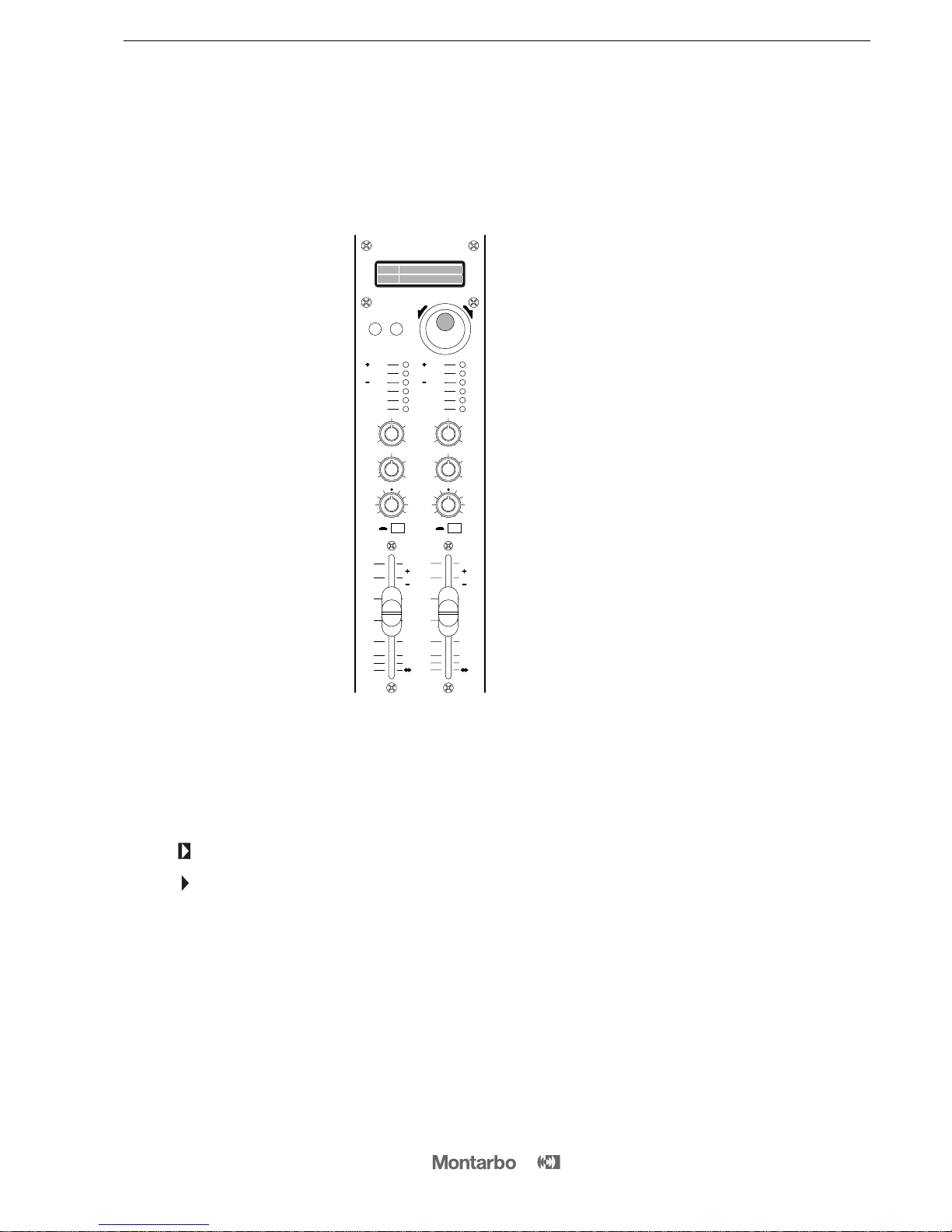
REGOLAZIONE DEGLI EFFETTI
1– Attivate gli effetti E1 ed E2 premendo
i rispettivi tasti ON. L’accensione viene
visualizzata dai LED rossi.
2– Portare i fader degli effetti E1/E2 e
dei master L/R in posizione 0.
3– Sui canali di ingresso ai quali desidera-
te aggiungere gli effetti, regolate il fader
di volume ed i potenziometri E1 e E2.
4– Prestate attenzione ai livelli visualizzati
sulle barre LED: • i LED rossi possono
lampeggiare saltuariamente.
• l'accensione continua dei LED rossi è
indice di segnali eccessivamente forti,
che possono dare origine a sgradevoli
distorsioni. Ciò non è da imputarsi ad un
difetto o ad un limite della macchina, ma
è comune alla tecnologia dei processori
digitali di qualsiasi tipo. Le barre LED
servono appunto per avvertire che è
necessario ridurre i livelli impostati con i
potenziometri E1 o E2 sui canali.
5– Se desiderate modificare il timbro
dell'effetto, potete agire sul controllo
TONE per 'scurire' (ruotando la manopo-
la in senso orario) o 'schiarire' (ruotando
la manopola in senso antiorario) la sono-
rità del programma selezionato.
6– Assegnate i due effetti alle uscite master L ed R con i potenzio-
metri BAL e/o all'uscita Aux (per avere l’effetto sui monitor) con il
potenzio-metro AUX e regolate il volume dell'effetto con il fader.
7– Mediante il pulsante 'E1/E2' scegliete su quale gruppo di effetti
andare ad agire (il gruppo scelto verrà visualizzato sul display sulla
riga corrispondente). Selezionate ora il programma desiderato
mediante la manopola 'PROGRAMS'. Quindi per memorizzare il
programma appena selezionato premete il pulsante 'LOAD'.
La freccia indica che il programma selezionato è stato caricato
(memorizzato), ed è attivo.
La freccia indica che il programma selezionato non è ancora
stato caricato (memorizzato).
Ripetete la stessa operazione per il secondo gruppo di effetti.
Utilizzate come riferimento la tabella riportata nella colonna a fianco
per imparare a conoscere le sonorità dei diversi programmi.
■Suggeriamo iniziare dai seguenti numeri per “sentire“ gli esempi
più rappresentativi degli effetti che avete a disposizione:
05 (STEREO GEN.), 20 (HALO), 35 (ECHO), 47 (ECHO+REV.),
57 (VOICE REV.), 66 (PERCUSSION REV.), 75 (HALO + REV.),
86 (PING PONG), 93 (EARLY REFLECTIONS), 109 (STEREO FLANGER),
113 (STEREO CHORUS), 125 (DETUNE), 135 (DUAL PITCH),
139 (SINGLE PITCH), 145 (PITCH + REV.), 155 (REVERS + REV.).
Sperimentate liberamente tutti gli effetti, senza alcun timore, fino a
che non individuate i programmi che creano l’effetto più gradevole
al vostro orecchio.
40
30
18
6
0
6
50
TONE
8
10
64
2
0
TONE
8
10
64
2
0
AUX
8
10
64
2
0
AUX
8
10
64
2
0
BAL RLBAL RL
40
30
18
6
0
6
50
10
3
0
3
20 10
3
0
3
20
ON ON
dB
dB
INPUT
LEVEL INPUT
LEVEL
E1 E2
ON ON
E1/E2 LOAD
PROGRAM SELECTOR
STEREO DIGITAL
EFFECTS PROCESSOR
E 1
E 2
P
R
O
G
R
A
M
S
Programmi e descrizione degli effetti
00 →010
STEREO GEN.
Aggiunge un breve ritardo al segnale processato, che dilata il fronte
stereofonico.
011 →030
HALO
Versione digitale del tipico effetto 'ALONE' degli eco a rullo Montarbo
degli anni '60, un classico del 'vintage' che non accenna a passare di
moda.
031 →040
ECHO
Classico eco 'ribattuto' con ritardo crescente nei programmi superiori.
041 →050
ECHO + REVERB
Combinazione di eco e riverbero, di grande incisività, utilizzato in
tantissime produzioni musicali.
051 →060
VOICE REVERB
Serie di riverberi specifici per dare risalto alla voce.
061 →070
PERCUSSION REVERB
Serie di ambienti creata per arricchire i suoni percussivi acustici e digitali.
071 →080
HALO + REVERB
Serie di combinazioni di halo e riverbero.
081 →089
PING PONG
Classico effetto 'autopan delay' presente sui dischi che hanno fatto la
storia del pop-rock. Le ripetizioni dell'eco si alternano tra canale destro
e canale sinistro.
090
BOUNCE
Effetto che produce ripetizioni all’inizio rarefatte e poi sempre più dense
e brevi.
091 →100
EARLY REFLECTIONS
Aggiunge al segnale le cosiddette 'prime riflessioni' di un riverbero, ma
senza includere la 'coda' dell'effetto. Arricchisce un suono rendendolo
più corposo ed aggressivo senza allungarne il tempo di decadimento. Si
adopera di solito per rinforzare la voce, le percussioni o gli assolo dei fiati.
101 →110
STEREO FLANGER
Può considerarsi un chorus molto intenso, con due voci che incrociano
la loro immagine stereo ed in cui la presenza del feedback crea un filtro
a pettine. I picchi ed i buchi di frequenza del filtro variano continuamente,
producendo così l'inconfondibile suono flanging.
111 →120
STEREO CHORUS
Fornisce un suono caldo e ricco. Dal segnale di ingresso vengono ricavate
tre voci che vengono inviate ai canali L, R ed al centro. Il risultato è che
anche il timbro più sottile suonerà come un ensemble. É ideale per dare
corpo alla voce, per ravvivare un accompagnamento di chitarra.
121 →130
DETUNE
Varia lievemente l’intonazione del suono originale creando un effetto di
raddoppio molto realistico con sfasamento crescente nei programmi su-
periori.
131 →136
DUAL PITCH
Splendido 'harmonizer' a due voci, che traspone in tempo reale il suono
all'ingresso. La voce può automaticamente godere di un coro al proprio
fianco.
137 →140
SINGLE PITCH
Harmonizer a una voce che traspone l’intonazione del suono in tempo
reale.
141 →150
PITCH CHANGE + REVERB
È la combinazione dei due effetti che danno maggiore corpo e calore
alla voce. Il 'pitch change' mette a disposizione una voce, al centro
dell'immagine stereo, oltre alla vostra originale. All'effetto di harmonizer
risultante viene aggiunto in cascata un caldo riverbero di tipo 'plate',
appositamente studiato per la voce.
151 →160
REVERSE REVERB
Un classico effetto del sound anni '80 produce un riverbero al contrario
che inizia a basso volume e aumenta man mano. Viene utilizzato
soprattutto con le percussioni.

__________________________________________
__________________________________________
__________________________________________
__________________________________________
__________________________________________
__________________________________________
__________________________________________
__________________________________________
__________________________________________
__________________________________________
__________________________________________
__________________________________________
__________________________________________
CONTENTS
Front and rear panels
Controls and connections
Important !
Stereo graphic equalizer
Dual stereo multieffects DSP
Appendix:
◗XD69
-
AD
69 Technical specifications
◗
XD69 Block diagram
◗
AD
69 Block diagram
◗
XD69
-
AD
69
Connections
◗
XD69
Connection examples
◗
AD69
Connection examples
2
10 - 12
13
13
14
16
17
18
19 - 23
24
25
ENGLISH
9
IMPORTANT ! Safety instructions
The lighting flash with arrowhead symbol within an equilateral triangle, is intended
to alert the user to the presence of uninsulated "dangerous voltage" within the
product's enclosure, that may be of sufficient magnitude to constitute a risk of
electric shock to humans.
The exclamation point within an equilateral triangle, is intended to alert the user
to the presence of important operating and maintenance (servicing) instructions.
WARNING !
In order to protect your own and others' safety and to avoid
invalidation of the warranty of this product, please read this
section carefully before operating this product.
-This product has been designed and manufactured for being operated as
mixing console/powered mixing console in the applications tipical of a
sound reinforcement system
or of a sound recording system. Operation for
purposes and in applications
other than these has not been covered by the
manufacturer in the design of the product, and is therefore to be
undertaken at end user's and/or installer's sole risk and responsability.
To avoid the risk of fire and/or electrical shock:
•Never expose this product to rain or moisture, never use it in proximity of
water or on a wet surface. Never let any liquid, as well as any object, enter
the product. In case, immediately disconnect it from the mains supply and
refer to servicing before operating it again.
•Before connecting this product to the mains supply, always make sure
that the voltage on the mains outlet corresponds to that stated on the
product.
•This product must be connected only to a grounded mains outlet
(complying to the safety regulations in force) via the supplied power cable.
In case the power cable needs to be substituted, use exclusively a cable
of the same type and characteristics.
•Never place any object on the power cable. Never lay the power cable
on a walkway where one could trip over it. Never press or pinch it.
•During operation do not cover the mixer and do not keep it in
containers which may prevent correct air circulation. Never obstruct the
air intake openings (AD69).
•In case the external fuses need replacement, substitute it only with one
of the same type and rating, as stated on the product.
•Always make sure the On/Off switch is in its 'Off' position before doing
any operation on the connections.
•Before attempting to move the product after it has been installed,
remove all the connections.
•To disconnect the power cable from the mains supply never pull the
cable directly instead, hold the body of the plug firmly and pull it gently
from the mains supply outlet.
-Before placing the product on a surface of any kind, always make sure
that its shape and load rating will safely match the product's size and
weight.
-
To avoid shocks always reserve a protected area with no access to unqualified
personnel as installation site of the product. In case the product is used near
children and animals closest supervision is necessary.
-This product in combination with headphones or speakers can generate
very high acoustic pressures which are dangerous for the hearing system.
Do not operate for a long period of time at a high or unconfortable volume
level. Never expose children to high sound sources.
CAUTION !
These products do not contain user serviceable parts.
To prevent fire and/or electrical shock, never remove their covers.
Maintenance and servicing must be carried out the official
Montarbo Distributor in your State or by qualified personnel
specifically authorized by the distributor.

10
CONTROLS AND CONNECTIONS
MONO INPUT CHANNEL
1 ➤GAIN: adjust the gain (sensitivity) of the line and mic inputs,
allowing connections of signal sources (both line and mic level)
having a wide range of signal level. As a practical rule, the GAIN
control must be set to the maximum allowable level that will not
activate the peak level indicator (CL). This will maximize the signal
to noise ratio.
2 ➤H.F / M.F / L.F: 3-band Equalizer.
H.F.: adjusts the amount of high frequencies giving up to 15dB of
boost or cut at 15kHz.
M.F.: adjusts the amount of mid frequencies giving up to 15dB of
boost or cut at 600Hz.
L.F: adjusts the amount of low frequencies giving up to 15dB of
boost or cut at 50Hz.
Note: Turning the control clockwise increases the amount of high, mid or low
frequencies, counter-clockwise decreases it. The response is flat at the center
position.
3➤AUX: auxiliary send volume (post EQ, pre fader). It sets the
level of that input channel into the auxiliary output.
4➤E1: effect send 1 volume (post-fader and post EQ). It adjusts
the quantity of channel signal that is sent to the correspondent
built-in effect.
Note: On the channels where you don't want to have the internal effect E1, turn
this knob fully anticlockwise.
5 ➤E2: effect send 2 volume (post-fader and post EQ). It adjusts
the quantity of channel signal that is sent both to the correspondent
built-in effect E2 and to an external effect connected to the EFF 2
SEND socket.
Note: On the channels where you don't want to have neither the internal effect
E2 nor the external effect, turn this knob fully anticlockwise.
Should the external effect only be required, then turn off the E2 internal effect.
6➤PAN: this control allows to place the channel’s input signal
within the stereo image by assigning more or less of the signal
to the left or right master outputs.
7➤ON: channel's main on/off switch. When pushed, the channel's
signal is sent to the L/R master outputs, AUX output and E1/E2
effect sends. We suggest to switch all unused channels off, to
reduce the noise in the outputs.
8➤Channel VOLUME fader.
9➤CL: peak LED indicator. It lights when the signal level is
approaching the maximum (clipping) allowable level. The signal
is sampled in two points of the channel's signal path: after the input
amplifier (micro and line) and after the equalizer.
If the LED is continuously lighted, you must reduce the input GAIN
or modify the equalizer settings, reducing the boost introduced by
the EQ controls HF, MF and LF.
10 ➤PHANTOM 48V DC: pushbutton for switching on/off the
48V phantom power supply on channels 4, 5, 6 (the phantom
power supply allows use of condenser microphones).
Note: Push this button when the unit is turned off or make sure that the faders
of channels 4, 5 and 6 are at their lowest settings.
●
connections:
11 ➤MIC: balanced XLR microphone input (for microphones).
12 ➤LINE / INSERT: unbalanced jack line input (for instruments
and high level sources). Also usable as insert in/out socket.
Note:
Do not connect instruments or other high level sources to the MICRO inputs
(this will result in distortion due to excessive signal level).
Do not connect microphones to the LINE inputs (the resulting signal will be of
low level and low quality) .
STEREO INPUT CHANNEL
13 ➤GAIN: same as in the mono channel.
14 ➤H.F / M.F / L.F.: same as in the mono channel.
15 ➤AUX: same as in the mono channel.
16 ➤E1: same as in the mono channel.
17 ➤E2: same as in the mono channel.
18 ➤BAL: stereo balance. Allows to adjust the level of the input
signal in the left or right master outputs. If the channel is used as
a mono channel it becomes a PAN control.
19 ➤ON: channel's main on/off switch. Same as in the mono
channel.
20 ➤Channel VOLUME fader.
21 ➤CL: same as in the mono channel.
●
connections:
22 ➤MIC: balanced mono XLR input for mic-level signals.
23 ➤L/R: unbalanced jack line inputs for stereo instruments.
For 'mono' connections use 'L/mono' input.

DUAL STEREO MULTIEFFECTS DSP
With 56-bit internal DSP and 24-bit Delta-Sigma conversion, the
two internal effects (160 programs each) provide high performance
digital audio processing combined with extremely easy operation.
24 ➤2-Line (E1 and E2) Liquid Crystal Display. Shows the numbers
and the names of the currently selected program.
25 ➤E1/E2 BUTTON: it allows operating on E1 or E2 lines on the
LCD (E1 and E2 are the two groups of effects).
26 ➤PROGRAMS KNOB: programs selection keys. It allows
selecting one of the 160 programs available for each of the two
effects (E1 and E2).
27 ➤LOAD BUTTON: allows loading and activating the program
selected with the PROGRAMS knob.
= shows that the selected program has been loaded.
= shows that the selected program has not been loaded yet.
28 ➤INPUT LEVEL: 5-segment input level LED indicator.
A good setting of the effect sends (E1 and E2) on each channel will
produce continuous lighting of the green LED segments, while the
red segment must flash only occasionally.
☞If the red LED is continuously lighted it indicates signal overload
and it is necessary to reduce the effect send volumes (E1 and E2)
on individual channels.
29 ➤TONE control: Turning this control clockwise produces a
gradual decrease in high frequencies. Fully anticlockwise the
response is flat.
30 ➤AUX: auxiliary send. Allows to adjust the level of the stereo
effect in the Aux (monitor) output.
31 ➤BAL: balance. Allows to adjust the level of the stereo signal
in the L and R master outputs.
32 ➤ON: effect on/off button, with red LED indicator.
33 ➤VOLUME fader.
●
connections:
34 ➤E1 / E2 FT/SW: jack sockets for connection of remote
footswitches. They allow remote control enabling/disabling of the
built-in effect processors. This is possible only when the 'ON'
buttons are pushed.
EXTERNAL EFFECTS SENDS AND RETURNS
35 ➤EXT EFF 2 SEND: level control for the external effect send. It is
the mix of the signals sent from the E2 send volume on each channel
and sets the level of the signal appearing at the EFF 2 SEND jack
output.
36 ➤EXT EFF 2 RETN: level control for the external effect return.
Sets the signal level of the external effect return.
37 ➤EXT EFF 2 TO AUX: sets the level of the external effect to be
sent to the AUX output (monitor).
38 ➤EXT EFF 2 BAL: stereo balance of the external effect.
Allows to adjust the level of the stereo signal of the effect in the
L and R master outputs.
●
connections:
39 ➤EFF 2 SEND: jack output socket for the external effect send.
40 ➤EFF 2 RETN L/R: 2 jack inputs for the external effect return.
• They can also be used as 2 extra line inputs.
■Connect the EFF2SEND output to the input of the external effect.
■Connect the L and R outputs of the stereo external effect to the
L and R EFF 2 RETN inputs of the stereo effects return.
•For a mono effect connect its 'only effect' output to the 'L / mono' socket.
■Use the E2 controls on each channel to determine the quantity
of channel's signal to be sent to the external effect, the EXT EFF 2
SEND control (35)to determine the quantity of signal to be sent to
the EFF 2 SEND, and the EXT EFF 2 RTN, EXT EFF 2 TO AUX and EXT
EFF 2 BAL (36,37,38)controls to adjust the effect return level in the
'AUX OUT' and master 'L/R' output.
• The E2 control on each channel is also the effect send for the 2
nd
internal effect.
To exclude E2 internal effect, turn it off by releasing its 'on' button.
Note: The AUX output (if not used as monitor output) can be used in place of
the EFF
2 output. In this case the signal of the external effect is adjusted by
means of the AUX send control on each channel and it is thus fully independent
of the internal E2 signal.
☛
see fig. 5page 23
11
CONTROLS AND CONNECTIONS

MASTER SECTION:
41 ➤L/R MASTER: volume faders for the left and right master
outputs.
42 ➤LEFT/RIGHT LEVEL: two 12 segment LED arrays give istanta-
neous reading of L and R outputs levels.
43 ➤6-band stereo graphic EQUALIZER.
44 ➤PROCESSOR: pushing this button activates an internal
processor which has effect on the L and R master outputs allowing
to obtain a 'full-bodied' sound even with a soft sound level (very
useful when performing in clubs, small venues etc.).
In the XD69 this processor has effect only on the XLR outputs
whereas the L and R Insert sockets are not affected by it.
In the AD69 this processor affects the power amplifier outputs only.
45 ➤CTRL ROOM: level control for the control room stereo output.
46 ➤AUX MASTER: volume control for the auxiliary output.
The auxiliary master output is the mix of the individual channel's
AUX sends.
47 ➤TAPE IN VOL: sets the level of the signal from the 'Tape in'
socket of the mixer.
48 ➤PHONES VOL: level control for the stereo phones output.
49 ➤POWER: mains power switch.
●
connections:
50 ➤XD69 LEFT/RIGHT OUTPUTS: L/R master outputs for the
connection of power amplifiers or active speaker enclosures.
■Connect the L/R master outputs to the inputs of the self-powered
speaker enclosures or to the inputs of the power amplifiers.
Adjust the volume fader on each channel as well as the L/R master
volume faders. Each output can drive up to 10 parallel connected
active speaker enclosures or power amplifiers.
Note: Using standard mono jack plugs the L/R insert sockets may be used as
normal jack outputs. In this case the XLR outputs are disconnected.
☛
see fig. 1A page 19
51 ➤AD69 L/R SPEAKER OUTPUTS: output sockets for theinternal
power amplifiers. Minimum load impedance for each amplifier is 4Ω.
■Connect one or two 8 Ohms speakers for each output. Never
operate the internal power amplifiers with loads below 4 Ohms each.
Note: Each output is fitted with 2 jack and 1 XLR sockets (parellel connected)
and features speaker protection fuses, electronic protections, delayed power-up
sequence, automatic troubleshooting and forced cooling.
☛
see fig. 1B page 20
52 ➤L/R INSERT: these stereo jack sockets (post-master faders)
allow the connection of external auxiliary equipment such as stereo
equalizer,limiter, audio processor,etc… to the master outputs.
See connection example.
☛
see fig. 2A page 21
In the mixer XD69 they may also be used as normal jack outputs
(using standard mono jack plugs). In this case the XLR outputs are
disconnected.
☛
see fig. 2A page 21
CONTROLS AND CONNECTIONS
In the powered mixer AD69 these sockets can also be used as
preamp-outputs for connecting powered speakers or external
power amplifiers.
■It is possible to use the line and power outputs at the same
time. Take out the signal from the insert sockets by means of two
stereo jack plugs, in which you have previously joined the RING
with the TIP (see example in page 21) and send it to the inputs of
the active speakers by means of mono jack plugs.
☛
see fig. 2B page 21
• If you plug mono jack into the stereo insert sockets, the power outputs are
automatically excluded.
53 ➤L/R CTRL ROOM OUT: the Control Room outputs provide a
duplication of the master outputs signal. To feed your nearfield
monitors while playing or recording or to feed a separate, second
PA while performing live to allow different audiences listen at
different sound levels (louder on the dancefloor near you, softer
at the tables where people’s talking).
The output level is adjusted by means of the CTRL ROOM level
control, which is independent from the L/R master outputs volume
levels. Each of the two outputs can drive up to 10 active speaker
enclosures or power amplifiers.
☛
see fig. 3page 22
54 ➤AUX OUT: auxiliary output (monitor). It can drive up to 10
parallel connected powered monitors.
■Connect the AUX socket to the input of the self-powered stage
monitor.
☛
see fig. 4page 22
• If it is not required as monitor output, it can be used as effect send (see fig. 5).
55 ➤L/R TAPE IN/OUT: PIN in-out sockets. They allow connection
to stereo tape recorder.
■Connect the L/R TAPE OUT sockets to the inputs of the tape re-
corder (line in) and the outputs of the tape recorder (line out) to
the L/R TAPE IN sockets of the mixer. If the TAPE IN inputs are not
used, it is suggested to keep the TAPE IN volume control fully
closed, to keep output noise to the minimum.
■For playback: switch the recorder to play and adjust the TAPE IN
VOL control on the mixer (and the output volumes of the tape
recorder, if available).
■For recording: switch the recorder to the 'record' mode and
adjust the input volume of the tape recorder. Set the output
volume control of the tape recorder to its lowest setting. In case
your tape recorder has no output volume control, disconnect the
cables from the TAPE IN sockets. The signal sent to the tape
recorder is unaffected by the L/R master faders settings.
Note: The L/R Tape inputs accept any line signal. You can thus use them as 2
extra line inputs to connect instruments, expanders or the L/R outputs of a mixer.
☛
see fig. 6page 23
56 ➤PHONES OUT: output for stereo headphones.
57 ➤I.E.C power supply socket and mains fuse.
58 ➤Auxiliary GROUND socket.
12

IMPORTANT!
13
CARE AND MAINTENANCE
☞Never expose the mixer to heat sources such as radiators or other
products that produce heat.
☞Never expose the mixer to direct sunlight, excessive vibrations or
mechanical shocks.
☞Avoid operating and storing the mixer in damp or dusty
places: this will avoid malfunctions and premature degrading of
specifications.
☞Avoid using the mixer close to strong sources of electromagnetic
interferences (e.g. video monitors, high power electrical cabling).
This may lead to degradation of audio quality.
☞Take care of the connection cables, always coil them avoiding
knots and twists.
☞Care should be taken so that objects do not fall and liquids are
not spilled into the mixer. In public event don't let people, musicians,
technicians or anyone put glasses, cups, ashtrays and cigarettes on
the mixer.
☞Never apply excessive force to the controls (knobs, sliders,
pushbuttons).
☞Use a soft brush or a jet of air to clean the panel.
Do not use alcohol, solvents or detergents.
☞If service is needed, refer to qualified service personnel only or
to the Montarbo distributor in your country.
INSTALLATION AND USE
☛When connecting the mixer to the mains supply: • check that
mains voltage corresponds to the voltage indicated on the panel;
• use the 3-wire power cord supplied; • always connect it to a
grounded outlet.
☛Always use quality cables and connectors.
☛Use shielded cables for your connections to the micro and line
inputs, to the send/return sockets, to the aux output, to the tape
in/out and L/R insert sockets and to the control room outputs.
STEREO GRAPHIC EQUALIZER
Careful use of the graphic equalizer can help the overall system
sound more natural in less than perfect acoustic environments and
allows to reduce feedback. For a proper setting of the controls of
the graphic equalizer consider the following:
• Avoid settings with all sliders up or all sliders down. This would
involve a useless increase in noise or a reduction of dynamic range.
• Choose carefully the placement of loudspeakers and micropho-
nes to minimize feedback before using the equalizer, in order to
get the most volume before feedback is heard. Otherwise you risk
removing significant amounts of your program material and altering
too much your sounds.
☛In the mixer XD69 use shielded cables for the connection of
active speaker enclosures to the L/R master outputs of the mixer.
☛In the powered mixer AD69 use unshielded cables for the
connection of passive speaker enclosures to the powered outputs
of the mixer. Never operate the internal power amplifiers with loads
of less than 4 ohm each.
☛Before switching on or off the mixer, 'close' (set to minimum the
outputs faders) the master outputs. This will avoid switching noises
that may cause damages to loudspeakers.
PRELIMINARY CONNECTIONS AND SETTINGS
❉Connect the speaker enclosures (active speakers to the XD69,
passive speakers to the AD69), the microphones, the instruments
and any auxiliary equipment.
❉Before turning on the mixer, set the channel volume faders and
the master volume faders to their lowest settings.
❉Switch on the unit and turn the gain controls to their lowest
settings, the tone controls and panpots to the middle position, and
the auxiliary and effect sends anti-clockwise to their lowest settings.
☛To optimize dynamics of each channel according to the
various signal sources, proceed as follows: • using a microphone
(connected to the XLR mic input) in conditions typical of the
intended use, set the GAIN control so as to cause the Peak LED to
illuminate; • now reduce the GAIN just enough until the peak LED
switches off and adjust the volume. ☛The channel's peak LED is
affected only by the GAIN control and the TONE controls.
Note: Repeat the above procedure for all the channels, one at a time, using the
signal source assigned to that channel and simulating real operating conditions
as closely as possible.
❉Set the volume faders of the L/R master outputs and of the
internal effects near to the '0' setting and the aux volume control
to the middle position, and now adjust the volume (7) of each
channel according to your requirements .
• With the graphic equalizer’s controls set to the zero mark
(centered) adjust the tone controls of each channel until you get
the tonal color you want for each microphone or instrument.
Once you have adjusted the tone controls of each channel, start
adjusting the controls of the graphic equalizer to compensate for
the acoustic environment and speaker placement.
This will allow you to compensate for different acoustic environ-
ments acting only on the equalizer’s setting with no need to modify
the tone controls settings of each channel.
80 Hz
50020080 1600 4000 10000 Hz
0
3
6
9
12
3
6
9
12
Hz
Hz
0
3
6
9
12
3
6
9
12
200 500 1600 4000 10000
80 Hz
50020080 1600 4000 10000 Hz
0
3
6
9
12
3
6
9
12
Hz
Hz
0
3
6
9
12
3
6
9
12
200 500 1600 4000 10000

14
DUAL STEREO MULTIEFFECTS PROCESSOR
The built-in effects processor has been designed for maximum ease
of use. It sports a wide range of high quality programs, all carefully
tailored to today’s music production requirements. At startup, programs
45 and 55 are auto-loaded: these ECHO+REV. and VOICE REV.
effects provide good results in the most different music styles, so
you will maybe want to use them as general purpose effects.
EFFECTS SETUP
1– Switch E1 and E2 to operation by
pushing their ON buttons.
A red LED lights up on each processor
to signal its status.
2– Bring the effects faders E1/E2 and
the L/R master faders near to the '0'
position on their scale.
3– Set the channel volume and the
effects sends levels with E1 and E2
controls on the input channels you wish
to add effects to.
4– Carefully check the input levels on
the LED bargraphs of both processors:
• the red LEDs should blink occasionally
• if the red LEDs are constantly lit, you
could suffer severe distortion on the
effect signal. This isn’t due to the proces-
sor itself, rather it is common on digital
processors of any price because of the
digital technology itself. In case, reduce
the levels of the E1 and E2 controls on
the input channels until the red LEDs
of LED bargraph light up only on loudest
peaks.
5– You can alter the effect timbre with
the TONE control on the effects processor:
turn it counter-clockwise to 'brighten' the
effects, or clockwise to 'darken' them.
6– Route the effects to the main outputs with the BAL control,
and/or to the stage monitors with the AUX control, then set their
volume faders at the desired levels.
7– Select the group of effects (E1 or E2) on which you want to
operate with the E1/E2 button. The selected group of programs will
be shown on the correspondent line on the display. Now select the
program, you wish to use, with the
knob PROGRAMS
. Use the
button LOAD to load the selected program.
= shows that the selected program has been loaded and is
active.
= shows that the selected program has not been loaded yet.
Use the chart on the next column as a reference to recognize the
programs.
■We suggest you start from the following program numbers so you
can listen to the most representative effects of each available effect
ranges:
05 (STEREO GEN), 20 (HALO), 35 (ECHO), 47 (ECHO + REV),
57 (VOICE REV), 66 (PERCUSSION REV), 75 (HALO + REV),
86 (PING PONG), 93 (EARLY REFLECTIONS), 109 (STEREO FLANGER),
113 (STEREO CHORUS), 125 (DETUNE), 135 (DUAL PITCH),
139 (SINGLE PITCH), 145 (PITCH + REV), 155 (REVERS + REV).
Feel free to experiment with any program until you get the sound
that most satisfies your taste.
40
30
18
6
0
6
50
TONE
8
10
64
2
0
TONE
8
10
64
2
0
AUX
8
10
64
2
0
AUX
8
10
64
2
0
BAL RLBAL RL
40
30
18
6
0
6
50
10
3
0
3
20 10
3
0
3
20
ON ON
dB
dB
INPUT
LEVEL INPUT
LEVEL
E1 E2
ON ON
E1/E2 LOAD
PROGRAM SELECTOR
STEREO DIGITAL
EFFECTS PROCESSOR
E 1
E 2
P
R
O
G
R
A
M
S
Programs and effects description
00 →010
STEREO GEN.
Adds a short delay to the signal to create a pseudo-stereo effect out of
mono sources.
011 →030
HALO
It’s a digital recreation of the effect built in the Montarbo reverb units
of the sixties, a vintage classic that never went out of fashion.
031 →040
ECHO
Classic multiplex effect. Delay time increases with program number.
041 →050
ECHO + REVERB
Delay and reverb blended together make for the impressive effect you
can listen on most contemporary productions.
051 →060
VOICE REVERB
Reverbs specially tailored to enhance vocals’ character.
061 →070
PERCUSSION REVERB
Ambience effects that enrich both acoustic and electronic percussions.
071 →080
HALO + REVERB
Halo and reverb effects blended together.
081 →089
PING PONG
Basically an auto-panned delay, popular on many rock hits, the samples
are being routed alternatively to full left and full right master.
090
BOUNCE
Repeats start widely spaced to become closer and closer.
091 →100
EARLY REFLECTIONS
Generates the initial part of the reverb without the decaying 'tail' of
the effect. It makes for thicker and more aggressive sound without
increasing its decay time. Usually it is used to colour vocals or horns
solos in contemporary productions.
101 →110
STEREO FLANGER
It may be considered as a very intense chorus, with two voices crossing
their stereo image and with feedback acting as 'comb filter'.
The frequencies corresponding to the filter's notches and peaks change
continuously, producing thus the typical flanging sound.
111 →120
STEREO CHORUS
It produces a warm and rich sound. Three voices are derived from the
input signal and are sent to the Left and Right channels and to the center.
The result is that even the thinner voice will sound like an ensemble.
It is ideal to enliven a guitar accompainment and to 'fatten' a voice.
121 →130
DETUNE
Slightly alters the tuning of the source to simulate a 'doubling' effect
with increased tuning alterations.
131 →136
DUAL PITCH
A wonderful 'harmonizer' with two voices trasposing the input signal
pitch in real-time. Your voice will be automatically accompanied by a
chorus.
137 →140
SINGLE PITCH
Harmonizer with one voice trasposing the input signal pitch in real-time.
141 →150
PITCH CHANGE + REVERB
It's the combination of the two effects which most of all let your voice
sound warmer and thicker. Beside your voice, the Pitch Change
provides a voice in the center of the stereo image. To the resulting
harmonizer effect a warm Plate type Reverb effect, particularly suited
for voice, is added in cascade.
151 →160
REVERSE REVERB
Unmistakably a 'must' of many 80's records, starts at low level, builds
up and quit abruptly. Usually served with percussion.

APPENDIX
15

16
TECHNICAL SPECIFICATIONS
MIXER SECTION
AMPS SECTION
XD69
6
- 60dB / 2,2 kΩ
- 30dB / 33 kΩ
48 V
30dB
- 128dB
H.F ±15dB@15kHz shelving
M.F ±15dB@600Hz
peaking
L.F ±15dB@50Hz shelving
3
- 60dB / 2,2 kΩ
- 48dB / 33kΩ
34dB
- 128dB
H.F ±15dB@15kHz
shelving
M.F ±15dB@600Hz
peaking
L.F ±15dB@50Hz
shelving
2 x 160 stereo effects
18 bit Delta/Sigma
56 bit
40Hz ÷15kHz
< 0,1%
> 98dB
-10dB
600Ω
+ 20dB
- 10dB
10kΩ
+ 20dB
0dB
+ 20dB
600Ω
0dB
100Ω
+ 22dB
600Ω
25Hz÷20kHz (+0 / -2dB)
< 0,03%
> 80dB
0dB / + 22dB
- 10dB
- 10dB
200 ÷600Ω
49,5 x 10 x 41 cm
6,5 Kg
AD69
6
- 60dB / 2,2 kΩ
- 30dB / 33 kΩ
48 V
30dB
- 128dB
H.F ±15dB@15kHz shelving
M.F ±15dB@600Hz
peaking
L.F ±15dB@50Hz shelving
3
- 60dB / 2,2 kΩ
- 48dB / 33kΩ
34dB
- 128dB
H.F ±15dB@15kHz
shelving
M.F ±15dB@600Hz
peaking
L.F ±15dB@50Hz
shelving
2 x 160 stereo effects
18 bit Delta/Sigma
56 bit
40Hz ÷15kHz
< 0,1%
> 98dB
-10dB
600Ω
+ 20dB
- 10dB
10kΩ
+ 20dB
0dB
+ 20dB
600Ω
0dB
100Ω
+ 22dB
600Ω
25Hz÷20kHz (+0 / -2dB)
< 0,03%
> 80dB
0dB / + 22dB
- 10dB
- 10dB
200 ÷600Ω
49,5 x 16 x 41 cm
14,9 Kg
2 built-in MOSFET (AB class) amplifiers
250 +250 W / 4Ω
400 + 400 W / 4 Ω
30Hz ÷25kHz (+0 / -1dB)
< 0,1% / 250 W / 4Ω
speaker protection fuses, electronic short
circuit protections, delayed power-up
sequence, forced cooling, automatic
trouble-shooting.
TECHNICAL SPECIFICATIONS
Mono Input channels:
micro (sensitivity / impedance)
line (sensitivity / impedance)
phantom power supply (on ch. 4, 5, 6)
channel gain control range
equivalent input noise
equalization
Stereo Input channels:
micro (sensitivity / impedance)
line L/R (sensitivity / impedance)
channel gain control range
equivalent input noise
equalization
Dual multieffect DSP
A-D and D-A conversion
DSP
bandwidth
THD
S.N.R
External effect send:
nominal level
impedance
max level
External effect return:
nominal level
impedance
max level
Aux Output
nominal level
max level
min. load impedance
L-R Master, C. Room outputs:
nominal level
impedance
max level
min load impedance
frequency response
THD
S.N.R
L-R Insert Outputs: nom. level / max. level
Tape in: nominal level
Tape out: nominal level
Headphones: load impedance
Dimensions:
Weight:
Amplifiers (processor controlled)
total output power (Watt continuous)
total output power (Watt peak)
frequency response
THD
protections

17
XD69 BLOCK DIAGRAM

18
AD69 BLOCK DIAGRAM

3
2
1
FIG. 1 A: XD69 L-R MASTER OUTPUTS
Connection of power amplifiers or active speaker
enclosures.
CONNECTIONS
GND +
GND 3
2 +
unbalanced XLR
female plug unbalanced
XLR male socket
XLR sockets:
☞
L/R OUTPUTS (unbalanced)
use heavy gauge shielded cables
GND
Rear panel of the XD69 mixer
ACTIVE SPEAKER ENCLOSURES
19
left outputright output
I
0
OUTPUTS
R
POWER RIGHT LEFT
L
1 - GND
2 - signal
3 - GND
220V-240V
50-60Hz
FUSE T 0,5A
1GND
mixer L and R outputs ➟inputs of active enclosures.

220V-240V
50-60Hz 1 - gnd
2 - signal
3 - n.c.
POWER
I
0
SPEAKER OUTPUTS
250W 250W
FUSE T 5A
FUSE
F 6,3A FUSE
F 6,3A
RIGHT LEFT
MIN LOAD 4
F
U
S
E
F
U
S
E
MIN LOAD 4
220V-240V
50-60Hz 1 - gnd
2 - signal
3 - n.c.
POWER
I
0
SPEAKER OUTPUTS
250W 250W
FUSE T 5A
FUSE
F 6,3A FUSE
F 6,3A
RIGHT LEFT
MIN LOAD 4
F
U
S
E
F
U
S
E
MIN LOAD 4
3
2
1
CONNECTIONS
FIG. 1 B: AD69 L-R POWERED OUTPUTS
Connection of passive speaker enclosures to the L/R
powered outputs.
Connect ONE or TWO 8 Ohms speakers to each output.
Rear panel of the AD69 powered mixer
8
Ω
8
Ω
8
Ω
8
Ω
Rear panel of the AD69 powered mixer
GND +
NC 3
2 +
unbalanced XLR
female plug unbalanced
XLR male socket
XLR sockets:
☞
L/R POWER OUTPUTS (unbalanced)
use heavy gauge unshielded cables
unbalanced
JACK socket
unbalanced mono
JACK plug
JACK sockets:
☞
L/R POWER OUTPUTS (unbalanced)
use heavy gauge unshilded cables
8
Ω
8
Ω
PASSIVE SPEAKER ENCLOSURES 8
Ω
8
Ω
PASSIVE SPEAKER ENCLOSURES
right output
right output left output
left output
NC
20
1GND
outputs of the internal power amplifiers ➟inputs of passive enclosures.
Other manuals for XD69
1
This manual suits for next models
1
Table of contents
Languages:
Other Montarbo Music Mixer manuals