Montarbo MX20 User manual

MANUALE D’ISTRUZIONI
OWNER’S MANUAL
ITALIANO
ENGLISH
DEUTSCH
FRANÇAIS
ESPAÑOL
3
-
10
11
-
18
19
-
26
27
-
34
35
-
42
APPENDIX
specications
block diagram
connectors
connections
43
-
50
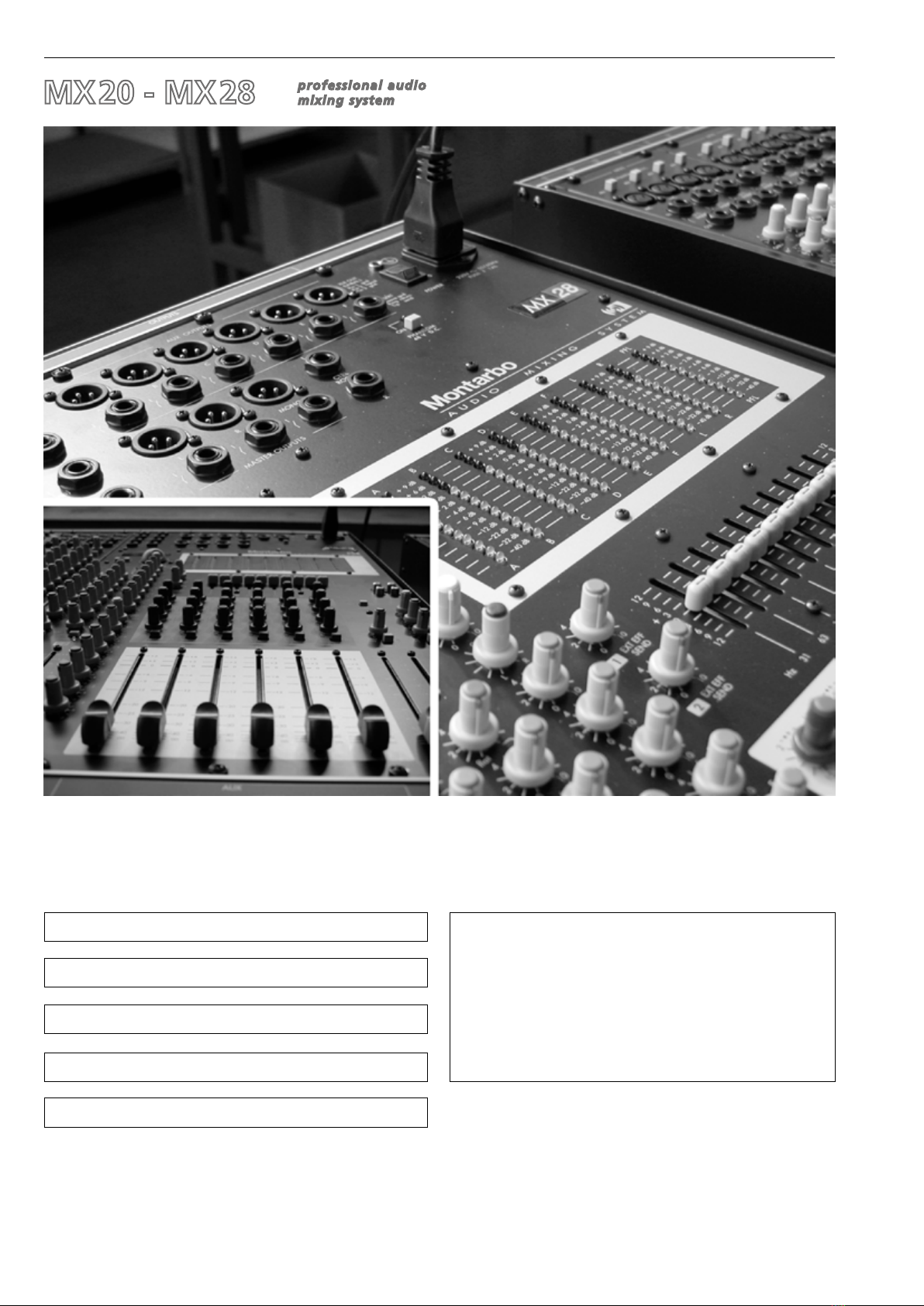
professional audio
mixing system
MX
20 - MX
28
Giugno 2015
June 2015
©2015 Elettronica Montarbo srl | M000072 | Rev. 01

professional audio
mixing system
MX
20 - MX
28
__________________________________________
__________________________________________
__________________________________________
__________________________________________
__________________________________________
__________________________________________
__________________________________________
__________________________________________
__________________________________________
__________________________________________
__________________________________________
INDICE
Pannello frontale
Controlli e connessioni
Equalizzatore graco stereo
Doppio DSP multieffetto stereo
Importante !
Appendix:
◗Dati tecnici
◗
Schema a blocchi
◗
Connettori
◗
Connessioni
3
IMPORTANTE ! Norme di sicurezza
ATTENZIONE !
Nell'interesse della propria e della altrui sicurezza, e per non
invalidare la garanzia, si raccomanda una attenta lettura di questa
sezione prima di adoperare il prodotto.
-Questo apparecchio è stato progettato e costruito per venire utilizzato
come mixer nel contesto tipico di un sistema di amplicazione sonora, e/o
di un sistema di registrazione sonora. L'utilizzo per scopi diversi da questi
non è contemplato dal costruttore, ed avviene pertanto sotto la diretta
responsabilità dell'utilizzatore/installatore.
Per evitare il rischio di incendio e/o di folgorazione:
•Non esporre il prodotto alla pioggia, non utilizzarlo in presenza di elevata
umidità o vicino all'acqua. Non lasciare penetrare all'interno dell'apparec-
chio alcun liquido, né alcun oggetto solido. In caso ciò avvenga, scollegare
immediatamente l'apparecchio dalla rete elettrica e rivolgersi ad un servizio
di assistenza qualicato prima di adoperarlo nuovamente.
•Prima di collegare l'apparecchio alla rete elettrica assicurarsi che la
tensione corrisponda a quella indicata sull'apparecchio stesso.
•Collegare questo apparecchio esclusivamente ad una presa di corrente
dotata di contatto di terra rispondente alle norme di sicurezza vigenti
tramite il cavo di alimentazione in dotazione. Nel caso in cui il cavo necessiti
di sostituzione, utilizzare esclusivamente un cavo di identiche caratteristiche.
•Non appoggiare alcun oggetto sul cavo di alimentazione. Non posarlo
dove possa costituire intralcio e causare inciampo. Non schiacciarlo e non
calpestarlo.
•Durante il funzionamento non coprite il mixer e non tenetelo dentro
a contenitori che possano ostruire la circolazione d'aria.
•In caso di sostituzione del fusibile esterno, utilizzare esclusivamente
un fusibile di caratteristiche identiche, come riportato sull'apparecchio.
•Prima di effettuare qualsiasi operazione di collegamento, assicurarsi
che l'interruttore di accensione dell'apparecchio sia in posizione 'Off'.
•Prima di effettuare qualsiasi spostamento del prodotto già installato
o in funzione, rimuovere tutti i cavi di collegamento.
•Per scollegare l'apparecchio dalla rete elettrica, non tirare mai il cavo, ma
afferrare sempre la spina.
-Nel predisporre l'apparecchio all'utilizzo, assicurarsi che la forma e la
por
tata della supercie di appoggio siano idonee a sostenerlo.
-
Per evitare urti riservate come luogo per l'istallazione del prodotto un'area
protetta inaccessibile a personale non qualicato. Qualora l'apparecchio
venga utilizzato in presenza di bambini e animali, si rende necessaria una
strettissima sorveglianza.
-Questo prodotto utilizzato insieme a cufe o a casse acustiche è in grado
di generare pressioni acustiche molto elevate, pericolose per la salute del
sistema uditivo. Evitarne quindi l'utilizzo ad elevati o fastidiosi livelli acustici.
◗Non esporre i bambini a forti sorgenti sonore !
ATTENZIONE !
Questo apparecchio non contiene parti interne destinate
all'intervento diretto da parte dell'utilizzatore. Per evitare il rischio
di incendio e/o folgorazione, non aprirlo.
Per qualsiasi intervento di manutenzione o riparazione, rivolgersi
alla Elettronica Montarbo srl e/o a personale altamente qualicato
specicamente segnalato da questa.
4
5 - 7
8
8 - 9
10
43 - 50
44
45
46
47 - 50
ITALIANO
Il lampo con la freccia inserito in un triangolo equilatero avvisa l'utilizzatore circa la presenza
di 'tensione pericolosa', senza isolamento, all'interno dell'apparecchio che potrebbe essere
sufcientemente alta da generare il rischio di scossa elettrica.
Il punto esclamativo inserito in un triangolo equilatero avvisa l'utilizzatore circa la presenza di
importanti istruzioni per l'utilizzo e per la manutenzione del prodotto.
ITALIANO
CONTENUTO DELL’IMBALLO
◗Mixer
◗Cavo di alimentazione
◗Manuale istruzioni
◗Certicato di garanzia
◗Dichiarazione di conformità CE

PANNELLO FRONTALE
MONO STEREO MASTER
4
ITALIANO

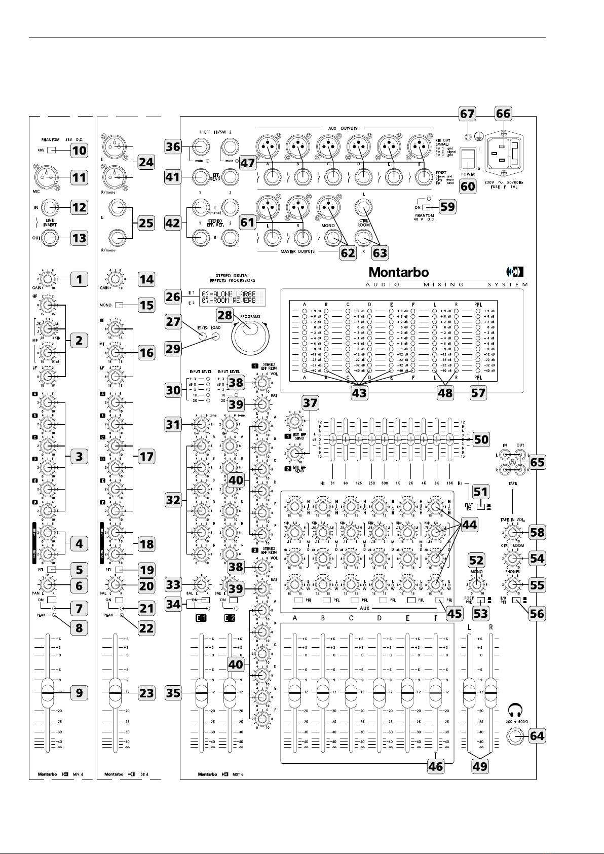
CONTROLLI E CONNESSIONI
CANALE D'INGRESSO MONO
1 ◗GAIN: controlla il guadagno dello stadio di ingresso, permette
do il collegamento di sorgenti sia microfoniche che di linea aventi
segnali di uscita estremamente variabili.
Come regola generale, al ne di contenere al minimo il rumore,
consigliamo di regolare il GAIN al massimo livello possibile, evitando
però che l'indicatore di picco (PEAK) si illumini.
2 ◗H.F / M.F. kHz / M.F. dB / L.F. Equalizzazione a 3 bande con
controllo parametrico sui medi. Mentre i controlli per i toni alti e
bassi agiscono su frequenze sse, il controllo dei toni medi consente
di scegliere la frequenza da attenuare o esaltare.
H.F: regola la quantità di accentuazione o attenuazione delle
frequenze alte (±15dB@15kHz). Girando la manopola in senso orario
si ottiene una accentuazione, in senso antiorario una attenuazione.
In posizione centrale la risposta è lineare.
M.F.kHz: determina la frequenza da esaltare o attenuare
(0,18÷3kHz).
M.F.dB: regola la quantità di accentuazione o attenuazione (±15dB)
della frequenza prestabilita mediante il comando M.F. kHz.
N.B: Se il comando M.F.dB è in posizione centrale non vi saranno
alterazioni nella banda media, indipendentemente dalla regolazione
del comando M.F.kHz.
L.F: regola la quantità di accentuazione o attenuazione delle
frequenze basse (±15dB@50Hz). Girando la manopola in senso ora-
rio si ottiene una accentuazione, in senso antiorario una
attenuazione. In posizione centrale la risposta è lineare.
3 ◗A / B / C / D / E / F: volumi mandate monitor.
Permettono di regolare la quantità di segnale del canale nelle
uscite monitor (dipendono dai controlli di tono e sono indipendenti
dal volume del canale).
4 ◗E1 / E2: volumi mandate effetti (dipendono dai controlli di tono
e volume del canale). Permettono di regolare la quantità di segnale
del canale da inviare sia al corrispondente effetto interno sia
all'eventuale effetto esterno collegato alle prese 'EFF SEND 1/2' e
'STEREO EFF.RET. 1/2'.
N.B: Sui canali dove non si vuole avere l'effetto interno e neppure
l'eventuale effetto esterno, girare questa manopola in senso
completamente antiorario. Se si vuole avere solamente l'effetto esterno,
disattivare l'effetto interno.
5 ◗PFL: questo pulsante permette di vericare mediante la rampa
di LED PFL (57) il livello del segnale di uscita del canale e di
ascoltarlo in cufa, anche con canale spento o con il fader di
volume chiuso, rendendo possibile, ad esempio, la regolazione
ottimale dell'equalizzatore. Se viene premuto il pulsante PFL di più
di un canale, alla cufa e all'indicatore PFL verrà inviata la somma
dei segnali dei canali selezionati.
N.B: Per preascoltare in cufa un canale occorre che il pulsante
dell'amplicatore cufa, presente nel modulo master (nr. 56) sia premuto.
6 ◗PAN: controllo di panorama. Permette di posizionare il segnale
(del canale) nell’immagine stereo inviandolo in quantità differente
alle uscite master L ed R.
7 ◗ON: pulsante per attivare o disattivare il canale, con indicatore
LED verde. Premendolo, il segnale del canale viene inviato alle uscite
master L/R, monitor A/B/C/D/E/F ed effetti E1/E2. Si consiglia di
tenere disinseriti i canali non utilizzati, in modo da ridurre il rumore
sulle uscite.
8 ◗PEAK: indicatore LED di picco. Si illumina quando il livello del
segnale è prossimo alla distorsione. Il segnale viene controllato
contemporaneamente in due punti del canale: dopo l'amplicatore
di ingresso (micro e linea) e dopo l'equalizzatore. Se il led PEAK si
accende con continuità, è necessario ridurre il guadagno di ingresso
(GAIN) o regolare diversamente l'equalizzazione del canale riducen-
do l'esaltazione introdotta dai comandi dei toni.
9 ◗VOLUME del canale.
10 ◗48V DC: pulsante per inserire/disinserire l'alimentazione
phantom (consente l'utilizzo di microfoni a condensatore).
N.B: Questo pulsante va premuto con tutti i volumi completamente
abbassati.
◗connessioni:
11 ◗MIC: ingresso microfonico bilanciato con connettore XLR
(per il collegamento di microfoni).
12 ◗LINE / INSERT IN: ingresso linea sbilanciato con connettore
jack per il collegamento di strumenti e sorgenti di segnale ad alto
livello. Utilizzabile anche come inserzione.
N.B:Non usare contemporaneamente i due ingressi MIC e LINE.
Non collegare strumenti (o altre sorgenti ad alto livello) all'ingresso MIC !
(questo comporterebbe distorsione dovuta al segnale eccessivo).
Non collegare microfoni all'ingresso LINE ! (il segnale sarà di basso livello
e qualità).
13 ◗INSERT OUT: uscita linea del canale su jack mono.
Pre-fader e pre-eq. Permette di inserire un accessorio esterno
(ad esempio un effetto o un equalizzatore) sul canale.
Collegare l'uscita Insert-Out all'ingresso dell'accessorio esterno
e l'uscita di quest'ultimo all'ingresso Line-In.
CANALE D'INGRESSO STEREO
14 ◗GAIN: come nel canale mono.
15 ◗MONO: pulsante che seleziona l'ingresso linea destro R come
ingresso mono, inviandone il segnale ad entrambe le sezioni L ed R.
16 ◗H.F / M.F / L.F. Equalizzazione a 3 bande.
H.F: controlla il livello delle frequenze alte. La frequenza di
intervento è 15kHz, l'accentuazione/attenuazione 15dB.
M.F: controlla il livello delle frequenze medie. La frequenza di
intervento è 600Hz, l'accentuazione/attenuazione 15dB.
L.F: controlla il livello delle frequenze basse. La frequenza di
intervento è 50Hz, l'accentuazione/attenuazione 15dB.
N.B:Girando la manopola in senso orario si ottiene una accentuazione,
in senso antiorario una attenuazione. In posizione centrale la risposta
è lineare.
17 ◗A / B / C / D / E / F: come nel canale mono.
18 ◗E1 / E2: come nel canale mono.
19 ◗PFL: come nel canale mono.
20 ◗BAL: controllo bilanciamento. Permette di regolare il livello
relativo destro/sinistro del segnale stereo del canale nelle uscite
master L/R. Se il canale viene usato in mono diventa un comando
PAN (panorama).
21 ◗ON: interruttore generale del canale. Come nel canale mono
22 ◗PEAK: come nel canale mono.
23 ◗VOLUME del canale.
◗connessioni:
24 ◗LINE L/R: ingressi linea bilanciati L / R su presa XLR.
25 ◗LINE L/R: ingressi linea bilanciati L / R su presa JACK.
Per il collegamento di strumenti stereo. Per collegamenti 'mono'
utilizzare l'ingresso 'R / mono' e premere il tasto MONO (15).
5
ITALIANO

DOPPIO DSP MULTIEFFETTO STEREO
I due processori sono basati su un DSP a 56 bit con conversione
Delta/Sigma a 24 bit. Ciascuno di essi offre 205 programmi di
grande qualità, prestazioni altamente professionali ed una estrema
facilità di utilizzo. Le dotazioni sono identiche per entrambi:
26 ◗DISPLAY a cristalli liquidi a due righe E1 ed E2.
Indica i numeri ed i nomi corrispondenti ai programmi selezionati.
27 ◗PULSANTE E1/E2. Permette di scegliere su quale gruppo di
effetti (E1 o E2, visualizzati sul display su due righe separate) agire.
28 ◗PROGRAMS: manopola di selezione dei programmi.
Permette di selezionare uno dei 205 programmi disponibili nella
memoria di ognuno dei due effetti.
29 ◗LOAD: pulsante che permette di caricare e rendere attivo il
programma selezionato mediante la manopola PROGRAMS.
La comparsa del simbolo sul display indica che il programma
selezionato è stato caricato.
La comparsa del simbolo sul display indica che il programma
selezionato non è stato ancora caricato.
30 ◗INPUT LEVEL: rampe a 5 LED per il controllo visivo del livello
di ingresso. Una buona regolazione delle mandate effetto (E1 ed E2)
sui singoli canali produrrà l'accensione dei LED verdi, mentre quello
rosso dovrà lampeggiare solo occasionalmente sui picchi di segnale.
◗Il LED rosso che resta continuamente acceso è indice di saturazio-
ne ed è perciò necessario diminuire il volume delle mandate effetto
(E1 ed E2) sui singoli canali.
31 ◗TONE: controllo di tono. Girando la manopola in senso orario
si produce una graduale attenuazione delle alte frequenze (in senso
completamente antiorario la risposta è lineare).
32 ◗A / B / C / D / E / F: mandate monitor. Sono indipendenti dal
volume dell'effetto (35). Permettono di regolare il livello dell’effetto
stereo sulle uscite monitor.
33 ◗BAL: bilanciamento. Permette di regolare il livello relativo
destro/sinistro del segnale stereo dell’effetto da inviare alle uscite
master L ed R.
34 ◗ON: pulsante per attivare o disattivare l’effetto, con indicatore
LED verde.
35 ◗Controllo di VOLUME dell'effetto sulle uscite master.
◗connessioni:
36 ◗EFF FT/SW - MUTE: prese jack per interruttori a pedale.
Consentono di disattivare gli effetti mediante pedale.
Ciò è possibile solo quando i relativi pulsanti "ON" sono premuti.
L'indicatore led 'MUTE' segnala che l'effetto è stato disattivato.
MANDATE E RITORNI EFFETTI ESTERNI
37 ◗1 / 2 effects send: controlli di volume per le mandate effetti
esterni. Regolano i livelli dei segnali presenti sulle uscite 'EFF
SEND 1' ed 'EFF SEND 2' e sono le miscelazioni dei segnali inviati
dalle mandate dei singoli canali.
Ognuno dei due RITORNI effetti STEREO dispone di:
38 ◗VOL: permette di regolare il segnale del ritorno effetti inviato
alle uscite master L ed R.
39 ◗BAL: bilanciamento stereo dell’effetto esterno.
Permette di regolare il livello relativo destro/sinistro del segnale
stereo dell’effetto da inviare alle uscite master L ed R.
40 ◗A / B / C / D: livelli del ritorno dell'effetto esterno sulle uscite
monitor. Regolano la quantità di effetto da inviare alle uscite A, B,
C e D. Dipendono dal controllo di volume (38).
CONTROLLI E CONNESSIONI
6
ITALIANO
◗connessioni:
41 ◗EFF SEND 1/2: uscite jack per le mandate agli effetti esterni.
42 ◗STEREO EFF RET 1/2: ingressi jack per i ritorni stereo degli
effetti esterni.
• Gli ingressi EFF RET L ed R sono normali ingressi di linea ed è perciò
possibile utilizzarli, per collegare qualsiasi segnale di linea (ad esempio
le uscite di un mixer, strumenti, expander…).
◗Collegare gli ingressi degli effetti esterni alle prese EFF SEND 1/2.
◗Collegare le uscite L ed R di ogni effetto esterno ai corrispondenti
ritorni stereo EFF RET 1 ed EFF RET 2.
• Per un effetto mono collegare l'uscita
'only effect'dell'effetto alla presa
'L/mono'
◗Utilizzare i controlli E1 ed E2 di ogni canale per regolare la quanti-
tà di segnale da inviare agli effetti esterni, i controlli EFF SEND 1 e
EFF SEND 2 (37) per regolare la quantità di segnale da inviare alle
uscite EFF SEND 1 e 2. Utilizzare i controlli A, B, C, D, VOL e BAL
(40, 38, 39) della sezione 'stereo eff. ret.' per regolare il ritorno
dell'effetto e le quantità dello stesso da inviare alle uscite 'A', 'B',
'C' e 'D' ed ai master 'L/R'.
Nei canali dove non si desiderano effetti o dove si desideri avere
uno solo dei due effetti esterni collegati ruotare i relativi comandi
di mandata (E1 e/o E2) in senso completamente antiorario.
◗
Figura 5pag. 50
SEZIONE USCITE AUSILIARIE
Questa sezione è formata da 6 canali identici (A, B, C, D, E ed F).
La seguente descrizione vale per ognuno di essi.
43 ◗A / B / C / D / E / F: rampe a 12 LED che indicano il livello delle
uscite ausiliarie A, B, C, D, E ed F.
44 ◗HIGH / MID kHz / MID dB / LOW: Equalizzazione a 3 bande
con controllo parametrico sui medi delle uscite monitor A, B, C, D,
E, F. Mentre i controlli per i toni alti e bassi agiscono su frequenze
sse, il controllo dei toni medi consente di scegliere la frequenza da
attenuare o esaltare.
HIGH: regola la quantità di accentuazione o attenuazione delle
frequenze alte (±15dB@15kHz). Girando la manopola in senso
orario si ottiene una accentuazione, in senso antiorario una
attenuazione. In posizione centrale la risposta è lineare.
MID kHz: determina la frequenza da esaltare o attenuare (0,18÷3kHz).
MID dB: regola la quantità di accentuazione o attenuazione
(±15dB) della frequenza prestabilita mediante il comando MID kHz.
N.B:Se il comando MID dB è in posizione centrale non vi saranno altera-
zioni nella banda media, indipendentemente dalla regolazione del
comando MID kHz.
LOW: regola la quantità di accentuazione o attenuazione delle
frequenze basse (±15dB@50Hz). Girando la manopola in senso
orario si ottiene una accentuazione, in senso antiorario una
attenuazione. In posizione centrale la risposta è lineare.
45 ◗PFL: pulsante che permette di vericare mediante la rampa di
LED PFL il livello del segnale delle mandate ausiliarie, e di ascoltarlo
in cufa, anche con volume chiuso.
É quindi possibile regolare la miscelazione e l'equalizzazione senza
inviare il segnale all'uscita. Se viene premuto più di un pulsante PFL,
alla cufa e all'indicatore PFL, verrà inviata la somma dei segnali
selezionati.
N.B: Per preascoltare in cufa un'uscita occorre che il pulsante dell'ampli-
catore cufa, presente nel modulo master (56) sia premuto.
46 ◗Fader per il livello delle uscite A, B, C, D, E ed F.

7
ITALIANO
CONTROLLI E CONNESSIONI
◗connessioni:
47 ◗A, B, C, D, E, F AUX OUTPUTS: dispongono ciascuna di una
presa XLR sbilanciata e di un jack stereo per l'inserzione di apparec-
chi esterni.
◗Collegare le prese di uscita A, B, C, D, E, F agli ingressi delle casse
monitor autoamplicate. Regolare le mandate monitor di ogni
canale (controlli A, B, C, D, E, F), i controlli di tono (44) e i volumi
(46) presenti sulla sezione 'AUX'.
N.B: Le prese jack Insert possono essere usate anche come uscite sbilancia-
te, utilizzando un jack mono standard. In tal caso le uscite XLR saranno
scollegate. Potete perciò utilizzare indifferentemente le uscite con gli
attacchi Jack o quelle con attacchi XLR a seconda del tipo di presa di cui
dispongono gli ingressi degli amplicatori o delle casse amplicate.
◗Ogni uscita può pilotare no a 10 casse acustiche autoamplicate
o nali di potenza collegati in parallelo.
◗
Figura 2pag. 48
SEZIONE MASTER
48 ◗L / R outputs level: rampe di LED a 12 segmenti che indicano
il livello delle uscite master L ed R.
49 ◗L /R MASTER: livelli generali per le uscite master L (sinistra)
ed R (destra).
50 ◗EQUALIZZATORE graco stereo a 10 bande sulle uscite master.
51 ◗EQ / FLAT: pulsante per inserire o disinserire l'equalizzatore
graco.
52 ◗MONO: controllo di livello dell'uscita mono.
53 ◗PRE / POST: questo pulsante permette di inviare all'uscita
'mono' un segnale indipendente (pre) o dipendente (post) dalla
regolazione dei volumi master L ed R.
54 ◗CTRL. ROOM: volume dell'uscita stereo CONTROL ROOM (63).
55 ◗PHONES: volume dell'uscita cufa.
56 ◗PFL L/R: questo pulsante permette di vericare mediante la
rampa di LED PFL (57) il livello del segnale del canale e dell'uscita
ausiliaria selezionata e di ascoltarlo in cufa (se sono premuti i
pulsanti PFL di più canali e di più uscite ausiliarie, in cufa viene
inviata la somma di tutti i segnali selezionati). A pulsante sollevato
viene inviato in cufa il segnale delle uscite L ed R.
57 ◗PFL: rampa di LED a 12 segmenti che indica il livello del
preascolto in cufa.
58 ◗TAPE IN VOL: volume dell’ingresso Tape.
59 ◗PHANTOM 48V D.C.: interruttore generale della alimentazio-
ne a 48V per microfoni a condensatore. Se non si usano microfoni
che richiedano l'alimentazione phantom, si consiglia di disinserire
questo pulsante.
60 ◗POWER: interruttore generale dell'apparecchio.
◗connessioni:
61 ◗L / R MASTER OUTPUTS: dispongono ciascuna di una presa
XLR sbilanciata e di un jack stereo per l'inserzione di apparecchi
esterni.
◗Collegare le prese di uscita L ed R agli ingressi dei nali di poten-
za o delle casse acustiche autoamplicate.
Regolare i fader dei volumi di ogni canale ed i controlli delle uscite
master L (sinistra) ed R (destra).
N.B: Le prese jack Insert possono essere usate anche come uscite
sbilanciate, utilizzando un jack mono standard. In tal caso le uscite XLR
saranno scollegate. Potete perciò utilizzare indifferentemente le uscite
con gli attacchi Jack o quelle con attacchi XLR a seconda del tipo di presa
di cui dispongono gli ingressi degli amplicatori o delle casse amplicate.
◗Ogni uscita può pilotare no a 10 casse acustiche autoamplicate
o nali di potenza collegati in parallelo.
◗
Figura 1 pag. 47
62 ◗MONO OUTPUT: su questa uscita è presente la somma delle
uscite master L ed R. Dispone di una presa XLR sbilanciata e di un
jack stereo per l'inserzione di apparecchi esterni.
◗Consente il collegamento a mixer, banchi di regia, amplicatori
o casse acustiche autoamplicate. Utile anche come ulteriore linea
monitor (side monitor). L'uscita 'mono' dispone di un controllo di
volume ed è inoltre commutabile 'pre' o 'post' master (53).
N.B: Le prese jack Insert possono essere usate anche come uscite sbilan-
ciate, utilizzando un jack mono standard. In tal caso le uscite XLR saranno
scollegate. Potete perciò utilizzare indifferentemente le uscite con gli
attacchi Jack o quelle con attacchi XLR a seconda del tipo di presa di cui
dispongono gli ingressi degli amplicatori o delle casse amplicate.
◗Ogni uscita può pilotare no a 10 casse acustiche autoamplicate
o nali di potenza collegati in parallelo.
◗
Figura 3pag. 49
63 ◗CTRL ROOM L / R: uscite Control Room. Sono utilissime in
tante situazioni di lavoro (piano-bar, club, ristoranti, teatri ecc…)
per pilotare un secondo gruppo di casse amplicate con controllo
di livello indipendente dalmaster, creando così due zone di ascolto
distinte a volumi differenti oppure per avere nei monitor un
controllo diretto del segnale di uscita.
Nelle applicazioni in studio l'utilizzo tipico è per i monitor di regia.
Il volume di questa uscita viene regolato mediante il comando
CTRL ROOM indipendentemente dai livelli delle uscite master L/R.
◗Ognuna delle due uscite jack può pilotare no a 10 casse
acustiche amplicate o nali di potenza.
◗
Figura 4pag. 49
64 ◗PHONES OUT: presa jack per cufa stereo.
65 ◗TAPE IN / OUT L/R: ingressi e uscite (prese PIN-RCA) per il
collegamento di un registratore stereo.
◗Collegare le prese TAPE OUT L/R del mixer agli ingressi (line in)
del registratore e le uscite (line out) del registratore alle prese
TAPE IN L/R del mixer. Se gli ingressi TAPE IN non vengono utilizzati,
si consiglia di tenere al minimo il volume TAPE.
◗ Per riprodurre nastri già registrati porre il registratore in riprodu-
zione e regolare opportunamente il volume "TAPE" del mixer
(ed i volumi di uscita del registratore, se presenti).
◗ Per registrare dall'impianto: porre il registratore in registrazione
e regolare opportunamente i volumi di ingresso del registratore.
Porre al minimo il volume di uscita del registratore. Nel caso in cui
il vostro registratore non disponga di questo controllo, scollegare
i cavetti dalle prese TAPE IN. Il segnale inviato al registratore non
dipende dalla regolazione dei volumi master L/R.
N.B: Gli ingressi TAPE IN L ed R sono normali ingressi di linea ed è perciò
possibile utilizzarli per collegare qualsiasi segnale di linea (ad esempio le
uscite di un mixer, strumenti, expander.....)
◗
Figura 6pag. 50
66 ◗Presa di rete a vaschetta con fusibile incorporato, per il
collegamento del cavo di alimentazione fornito di corredo.
67 ◗Presa di terra supplementare.

8
ITALIANO
EQUALIZZATORE GRAFICO STEREO
L’equalizzatore, se convenientemente utilizzato, consente di correg-
gere gli effetti dell’ambiente sulla resa timbrica dell’impianto e di
ridurre fastidiosi rientri.
Per una corretta regolazione dell’equalizzatore, è opportuno tenere
presente i seguenti accorgimenti:
• Non usare regolazioni con tutti i cursori vicini ad uno degli estremi
della corsa. Questo comporta un inutile aumento di rumore ed una
riduzione di dinamica.
• Stabilite attentamente la posizione migliore per le casse e per
i microfoni. Ciò vi consentirà di ridurre al minimo i rientri ancor
prima di servirvi dell’equalizzatore, e di eliminare la minor quantità
possibile di frequenze dal vostro programma sonoro.
• Con i cursori dell'equalizzatore in posizione centrale (sullo '0')
agire sui controlli di tono di ogni canale per ottenere la tonalità
desiderata dai singoli microfoni o strumenti. Solo dopo avere otte-
nuto una timbrica soddisfacente, regolare l'equalizzatore per com-
pensare le caratteristiche acustiche dell’ambiente.
In tal modo le differenze di resa tra un ambiente e l’altro possono
essere compensate utilizzando solo l’equalizzatore graco, senza
necessità di grosse variazioni delle regolazioni dei canali.
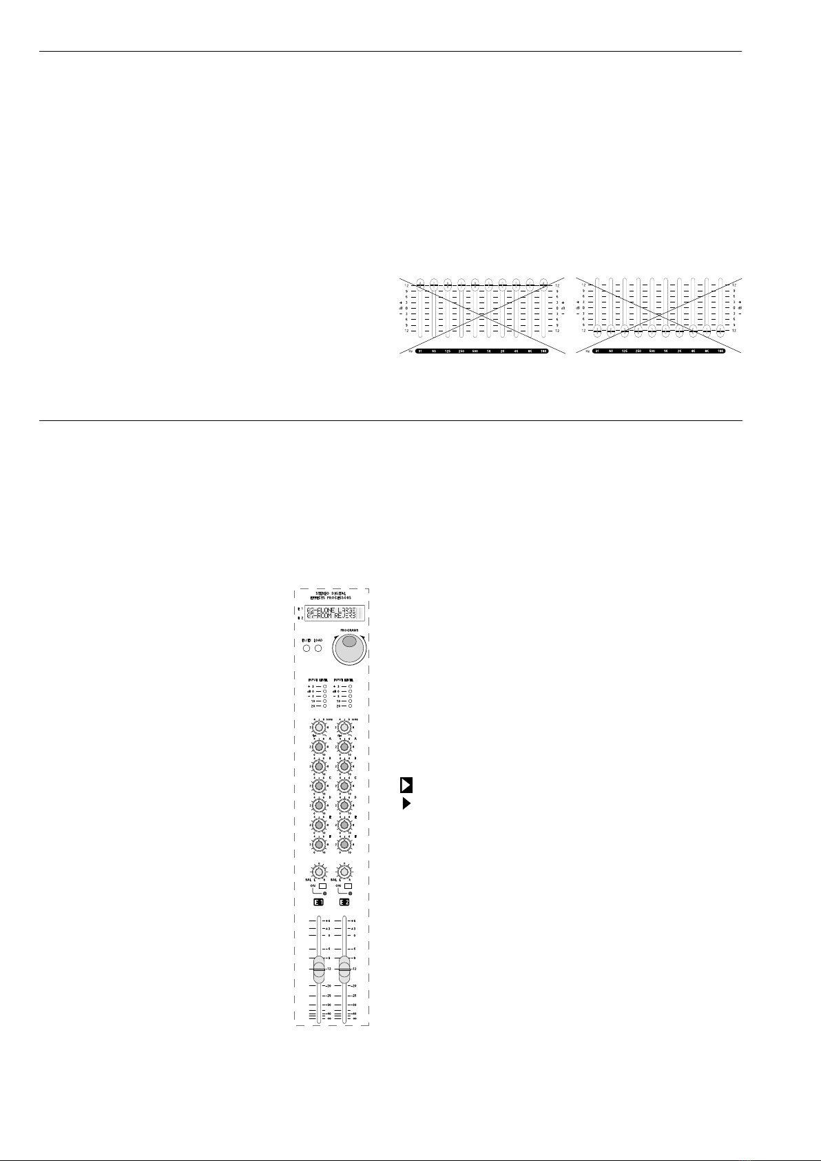
DOPPIO PROCESSORE MULTIEFFETTO STEREO
Il doppio processore di effetti stereo incorporato è caratterizzato
da estrema facilità d’uso e da una scelta di programmi di grande
qualità, in linea con le tendenze più avanzate della produzione
musicale. All’accensione, il processore carica automaticamente
i programmi 19 e 61 (rispettivamente, delle famiglie HALO e
CHAMBER).
REGOLAZIONE DEGLI EFFETTI
1- Attivate gli effetti E1 ed E2 premendo i
rispettivi tasti ON.
L’accensione viene visualizzata dai LED verdi.
2- Portare i fader degli effetti E1/E2 e dei
master L/R in posizione 0.
3- Sui canali di ingresso ai quali desiderate
aggiungere gli effetti, regolate il fader di
volume ed i potenziometri E1 ed E2.
4- Prestate attenzione ai livelli visualizzati
sulle barre LED:
• i LED rossi possono lampeggiare
saltuariamente;
• l'accensione continua dei LED rossi è
indice di segnali eccessivamente
forti, che possono dare origine a sgradevoli
distorsioni. Ciò non è da imputarsi ad un
difetto o ad un limite della macchina, ma è
comune alla tecnologia dei processori
digitali di qualsiasi tipo.
Le barre LED servono appunto per avvertire
che è necessario ridurre i livelli
impostati con i potenziometri E1 o E2 sui
canali.
5– Se desiderate modicare il timbro dell'effetto, potete agire sul
controllo TONE per 'scurire' o 'schiarire' la sonorità del programma
selezionato.
6– Assegnate i due effetti alle uscite master L ed R con i potenzio-
metri BAL e/o alle uscite Aux (per avere l’effetto sui monitor) con i
potenziometri A,B,C,D,E,F e regolate il volume dell'effetto con
il fader.
7– Mediante il pulsante 'E1/E2' scegliete su quale gruppo di effetti
agire (il gruppo scelto verrà visualizzato sul display sulla riga corri-
spondente). Selezionate ora il programma desiderato mediante la
manopola 'PROGRAMS'. Quindi per memorizzare il programma
appena selezionato premete il pulsante 'LOAD'.
La freccia indica che il programma selezionato è stato caricato
(memorizzato), ed è attivo.
La freccia indica che il programma selezionato non è ancora
stato caricato (memorizzato).
Ripetete la stessa operazione per il secondo gruppo di effetti.
nUtilizzate come riferimento la tabella riportata nella pagina
accanto per imparare a conoscere le sonorità dei diversi programmi.
nSperimentate liberamente tutti gli effetti, senza alcun timore,
no a che non individuate i programmi che creano l’effetto più
gradevole al vostro orecchio.

9
ITALIANO
L’impiego di potenti DSP di ultima generazione ha permesso di
sviluppare nuovi algoritmi che ricreano, in modo realistico, le
dimensioni sonore dei più svariati ambienti e una serie inedita di
programmi, ottimizzati per esaltare le caratteristiche acustiche di
ogni singolo strumento.
Programmi e descrizione degli effetti
1
◗
5
EARLY
Le prime riessioni del suono all’interno di un ambiente, prima che
cominci il vero e proprio riverbero.
6
◗
14
STEREO GEN
Generando brevi ritardi e sommandoli al segnale originale si percepisce
una maggiore apertura del suono monofonico.
15
◗
18
PING PONG
Suono ritardato (delay) che rimbalza da un canale all’altro, con ritardo
che cresce al crescere del numero del preset.
19
◗
23
HALO
Storico effetto che ripropone il famoso ‘eco a rullo’ Montarbo.
Consigliato per voci Vintage o Psyco.
24
◗
36
DELAY
Ritardi che aumentano al crescere del numero del preset e che
conferiscono una piacevole apertura al suono.
37
◗
40
DETUNE
Leggera alterazione nell’intonazione che arricchisce il suono senza
snaturarlo. Da provare su sezioni vocali tenute.
41
◗
45
FLANGER
Effetto molto incisivo che caratterizza fortemente il suono.
Sia i preset Mono che quelli Stereo rendono al meglio con strumenti
dal lungo Sustain.
46
◗
54
CHORUS
Modulando il ritardo e l’ampiezza del segnale trattato simula un vero
coro. I preset stereo danno un’apertura maggiore.
55
◗
57
AMBIENCE
Caratterizzato dalla predominanza di prime riessioni seguite da una
riverberazione appena accennata. Simula un ambiente dalle dimensioni
contenute e dalle pareti riettenti.
58
◗
61
CHAMBER
Ambiente leggermente più grande del precedente e con pareti che
assorbono maggiormente le riessioni.
62
◗
66
ROOM
Dimensioni analoghe a quelle di una stanza normale. I preset alternano
pareti riettenti ad altre assorbenti.
67
◗
73
HALL
Simulazione di un’ampia sala vuota, con pareti spoglie e piuttosto
riettenti: il tipico salone per le feste.
74
◗
75
CATHEDRAL
Viene riprodotta la sensazione di spazio che si ha all’interno di un
ambiente molto grande, come una cattedrale.
76
◗
78
PLATE
Prende il nome dai primi generatori di riverbero elettromeccanici, che
usavano piastre di metallo per produrre un suono grande e brillante.
79
◗
81
PLATE DLY
Al suono prodotto dalla famiglia ‘plate’ viene aggiunto un pizzico
di eco per rendere il suono ancora più grande.
82
◗
85
BIG SPACE
Viene ricreato un ambiente vastissimo, surreale ma sicuramente
suggestivo.
86
◗
88
ECO REV
Uno degli effetti più usati: unisce la profondità dell’eco al calore del
riverbero. Generalmente utilizzato sulle voci dei cantanti, rappresenta
il classico punto di partenza.
89
◗
92
CONCERT
Viene ricreato lo spazio sonoro di una sala da concerto ampia, ma con
riessioni controllate e dall'equilibrio tonale neutro.
93
◗
95
LIVE
Per provare la sensazione di cantare dal vivo all’aperto, sopra un grande
palco e davanti a migliaia di persone.
96
◗
99
GATE
La coda sonora del riverbero viene troncata bruscamente, rendendo il
suono molto particolare ed aggressivo.
100
◗1
34
VOX - FLUTE - TRUMPET - SAX - BRASS - KEYBRD - PIANO - GTR
- DRUM - TOMS - CYMB - HIHAT - KICK - SNARE - TOM
Questo gruppo di preset comprende degli effetti realizzati apposita-
mente per diversi strumenti, subito disponibili senza dover perdere
tempo con noiose programmazioni.
135
INSIDE A BOX
Simile al Room (62-66) ma l'ambiente ha dimensioni piccolissime.
136
LIVING ROOM
Come il precedente, ma le dimensioni dell'ambiente sono maggiori
(un tipico soggiorno).
137
◗
144
PTC REV
Al segnale trasposto come descritto nella famiglia ‘ pitch ’ viene
aggiunta una piacevole riverberazione.
145
◗
155
PITCH
Questi preset generano uno o più segnali alterati nell’intonazione ma
armonici con il segnale originale.
156
◗
165
DISTANCE
È un semplice ritardo del segnale di ingresso, utile nelle installazioni
con più linee di diffusori a distanza diversa dal pubblico.
Utilizzando le uscite AUX è possibile pilotare dei diffusori amplicati,
più vicini agli ascoltatori rispetto al sistema principale. Col crescere del
numero di preset il ritardo aumenta a passi di 5 metri.
166
◗
175
*
ECHO
Classico eco 'ribattuto' con ritardo crescente nei programmi
superiori.
176
◗
185
*
ECHO + REVERB
Combinazione di eco e riverbero, di grande incisività, utilizzato in
tantissime produzioni musicali.
186
◗
195
*
VOICE REVERB
Serie di riverberi specici per dare risalto alla voce.
196
◗
205
*
HALO + REVERB
Serie di combinazioni di halo e riverbero.
DOPPIO PROCESSORE MULTIEFFETTO STEREO

10
ITALIANO
IMPORTANTE!
CURA E MANUTENZIONE
• Questo prodotto è stato progettato per essere utilizzato in climi
tropicali e particolarmente caldi.
• Non porre sul mixer sorgenti di amme nude, quali candele
accese.
• Posizionare il mixer lontano da fonti di calore (caloriferi o qualsiasi
altro oggetto che produca calore).
• Evitate di esporre il mixer alla irradiazione solare diretta, ad ecces-
sive vibrazioni e a urti violenti.
• Evitate l’uso e il deposito in ambienti eccessivamente polverosi
o umidi: eviterete così cattivi funzionamenti e deterioramento
anticipato delle prestazioni.
• Nel caso in cui il mixer venga utilizzato all’aperto fare attenzione
a proteggerlo dalla pioggia.
• Evitate di utilizzare il mixer vicino a forti fonti di radiazioni
elettromagnetiche (monitor video, cavi elettrici di alta potenza):
ciò può provocare una diminuzione della qualità audio.
• Abbiate cura dei cavi di collegamento, avvolgeteli evitando
nodi e torsioni.
• Proteggere l'apparecchio dal rovesciamento accidentale di liquidi
o sostanze di qualsiasi tipo. In particolare nelle condizioni di utilizzo
tipiche, prestare la massima attenzione alla collocazione dell'appa-
recchio onde evitare che pubblico, musicisti, tecnici o chicchessia
possa poggiare bicchieri, tazze, contenitori di cibo o di bevande,
portacenere e sigarette accese sull'apparecchio.
• Non forzate i comandi (manopole, interruttori, cursori).
• Per rimuovere la polvere dal pannello usate un pennello o un
sofo d’aria. Non usate mai alcool, detergenti o solventi.
• In caso di necessità di assistenza, rivolgetevi alla Elettronica
Montarbo srl o a personale altamente qualicato.
INSTALLAZIONE ED USO
◗
Collegamento alla rete: • utilizzare il cavo di alimentazione a tre
poli di corredo; • collegarlo sempre ad una presa di corrente dotata
di contatto di terra; • accertarsi che la tensione di rete corrisponda
a quella indicata sull’apparecchio.
◗
Utilizzare cavi di collegamento e connettori di qualità.
◗
Utilizzare cavi schermati per i collegamenti agli ingressi
microfonici e linea, alle prese send/return, alle uscite master L/R
e monitor, alle prese tape in/out e all'uscita mono.
◗
Prima di accendere o spegnere l’apparecchio, chiudete (metten-do
al minimo i controlli) le uscite master, monitor e l'uscita mono.
COLLEGAMENTI E REGOLAZIONI INIZIALI
◗
Collegare le casse acustiche attive (o nali di potenza con le casse
passive).
◗
Collegare i microfoni agli ingressi XLR e gli strumenti agli ingressi
jack.
◗
Non collegate i microfoni agli ingressi LINE!
◗
Prima di accendere l'apparecchio, mettere tutti i volumi al minimo
ed i cursori dell'equalizzatore graco a zero (posizione centrale).
◗
Dopo avere acceso l'apparecchio, regolare i controlli di guadagno
di ogni canale al minimo, i controlli di tono e panorama in posizio-
ne centrale, le mandate monitor e le mandate effetto al minimo.
◗
Per ottimizzare la dinamica di ogni canale vi consigliamo di
effettuare le seguenti operazioni: • utilizzando il microfono
(collegato alla presa XLR) portare i fader dei volumi master L/R in po-
sizione vicina a '0' quindi portare il comando GAIN in posizione tale
da fare illuminare il LED di picco, • a tal punto diminuire il guadagno
di quel tanto da fare spegnere il LED di picco e regolare poi il fader
del volume del canale. Nel caso in cui il volume dovesse risultare
eccessivo attenuare i volumi sui nali di potenza o sulle casse auto-
amplicate collegate.
◗
Il LED di picco del canale è inuenzato esclusivamente dal
controllo di guadagno e dai controlli di tono.
N.B:un canale per volta, effettuare questa operazione su tutti i canali
utilizzando le fonti di segnale per essi predisposte (voce femminile, voce
maschile, strumenti) e nelle condizioni di impiego il più possibile reali.
◗
Portare i fader dei volumi degli effetti interni in posizione vicina
a '0' ed i volumi monitor in posizione centrale.

__________________________________________
__________________________________________
__________________________________________
__________________________________________
__________________________________________
__________________________________________
__________________________________________
__________________________________________
__________________________________________
__________________________________________
__________________________________________
CONTENTS
Front panel
Controls and connections
Stereo graphic equalizer
Dual stereo multieffects DSP
Important !
Appendix:
◗Technical specications
◗
Block diagram
◗
Connectors
◗
Connections
12
13 - 15
16
16 - 17
18
43 - 50
44
45
46
47 - 50
ENGLISH
11
IMPORTANT ! Safety instructions
The lighting ash with arrowhead symbol within an equilateral triangle, is intended to alert the
user to the presence of uninsulated "dangerous voltage" within the product's enclosure, that
may be of sufcient magnitude to constitute a risk of electric shock to humans.
The exclamation point within an equilateral triangle, is intended to alert the user to the
presence of important operating and maintenance (servicing) instructions.
WARNING !
In order to protect your own and others' safety and to avoid
invalidation of the warranty of this product, please read this
section carefully before operating this product.
-This product has been designed and manufactured for being operated as
mixing console in the applications tipical of a sound reinforcement system
or of a sound recording system. Operation for purposes and in applications
other than these has not been covered by the manufacturer in the design
of the product, and is therefore to be undertaken at end user's and/or
installer's sole risk and responsability.
To avoid the risk of re and/or electric shock:
•Never expose this product to rain or moisture, never use it in proximity of
water or on a wet surface. Never let any liquid, as well as any object, enter
the product. In case, immediately disconnect it from the mains supply and
refer to servicing before operating it again.
•Before connecting this product to the mains supply, always make sure that
the voltage on the mains outlet corresponds to that stated on the product.
•This product must be connected only to a grounded mains outlet
complying to the safety regulations in force via the supplied power cable.
In case the power cable needs to be substituted, use exclusively a cable
of the same type and characteristics.
•Never place any object on the power cable. Never lay the power cable
on a walkway where somebody could trip over it. Never press or pinch it.
•During operation do not cover the mixer and do not keep it in containers
which may prevent correct air circulation.
•In case the external fuse needs replacement, replace it with one of the
same type and rating, as stated on the product.
•Always make sure the On/Off switch is in its 'Off' position before doing
any operation on the connections to the product.
•Before attempting to move the product after it has been installed, remove
all the connections.
•To disconnect the power cable of this product from the mains supply never
pull the cable. Hold the body of the plug rmly and pull it gently from the
mains supply outlet.
-Before placing the product on a surface of any kind, always make sure that
its shape and load rating will safely match the product's size and weight.
-
To avoid shocks always reserve a protected area with no access to unqualied
personnel as installation site of the product. In case the product is used near
children and animals closest supervision is necessary.
-This product in combination with headphones or speakers can generate
very high acoustic pressures which are dangerous for the hearing system.
Do not operate for a long period of time at a high or unconfortable volume
level.
◗Never expose children to high sound sources.
CAUTION !
This product does not contain user serviceable parts.
To prevent re and/or electrical shock, never remove its cover.
Maintenance and servicing must be carried out the ofcial
Montarbo Distributor in your State or by qualied personnel
specically authorized by the distributor.
ENGLISH
professional audio
mixing system
MX
20 - MX
28
PACKAGE CONTENTS
◗Mixing console
◗Power supply cable
◗Owner’s manual
◗Warranty certicate
◗CE declaration of conformity
FRONT PANEL
MONO STEREO MASTER
12
ENGLISH

13
CONTROLS AND CONNECTIONS
MONO INPUT CHANNEL
1 ◗GAIN: adjust the gain (sensitivity) of the line and mic inputs,
allowing connections of signal sources (both line and mic level)
having a wide range of signal level. As a practical rule, the GAIN
control must be set to the maximum allowable level that will not
activate the peak level indicator (PEAK). This will maximize the
signal to noise ratio.
2 ◗H.F / M.F. kHz / M.F. dB / L.F: 3-band Equalizer with parametric
control of the mid range. The High and Low controls act on xed
frequency bands, the Mid control allows to choose the frequency to
be boosted or cut.
H.F: adjusts the amount of boost or cut in the high frequency
range (±15dB@15kHz). Turning the control clockwise increases the
amount of high frequencies, counter-clockwise decreases it.
The response is at at the center position.
M.F. kHz: chooses the frequency to be boosted or cut (0,18÷3kHz).
M.F. dB: adjusts the amount of boost or cut (±15dB) in the frequen
cy choosen by means of the M.F. kHz control.
Note: If the M.F.dB control is set at '0' (centre) there will be no alteration
in the mid frequency band (independently of the M.F.kHz control setting).
L.F: adjusts the amount of boost or cut in the low frequency range
(±15dB@50Hz). Turning the control clockwise increases the amount
of low frequencies, counter-clockwise decreases it. The response is
at at the center position.
3◗A / B / C / D / E / F: monitor sends volumes (post eq., pre fader).
They set the level of that input channel in the monitor outputs.
4 ◗E1 / E2: effect sends volumes (post-fader and post eq.).
They adjust the quantity of channel signal that is sent both to the
correspondent built-in effect and to an external effect connected
to the 'EFF SEND 1/2' and 'STEREO EFF. RET. 1/2' sockets.
Note: On the channels where you don't want to have neither the internal
effect nor the external effect, turn this knob fully anticlockwise. Should
the external effect only be required, then switch the internal effect off.
5◗PFL: allows to check the level of the channel's output signal
by means of the PFL level indicator (57) and to listen to it on the
headphones, even if the channel is switched off or the fader is
closed. It is so possible to adjust the equalizer without sending the
channel's signals to the outputs. If more than one PFL switch is on,
the phones amplier and the PFL LED indicator will receive the sum
of the selected channel's signals.
Note: To allow headphone listening of a PFL signal, the PFL switch of the
master module's headphone amplier (56) must be pressed.
6◗PAN: this control allows to place the channel’s input signal
within the stereo image by assigning more or less of the signal
to the left and right master volume controls.
7◗ON: channel's main on/off switch with green LED indicator.
When pushed, the channel's signal is sent to the L/R master outputs,
A/B/C/D aux outputs and E1/E2 effect sends. We suggest to switch
off every unused channel, to reduce the noise in the outputs.
8◗PEAK: peak LED indicator. It lights when the signal level is
approaching the maximum (clipping) allowable level. The signal
is sampled in two points of the channel's signal path: • after the
input amplier (micro and line), • after the equalizer.
If the LED is continuously lighted, you must reduce the input GAIN
or modify the equalizer settings, reducing the boost introduced by
the tone controls.
9◗Channel VOLUME fader.
10 ◗48V DC: pushbutton for on/off switching of the 48V
phantom power supply (the phantom power supply allows use
of condenser microphones).
Note: Before pushing this button, make sure that the unit is turned off or
that all the slider controls are to their lowest settings.
◗
connections:
11 ◗MIC: balanced XLR microphone input (for microphones).
12 ◗LINE / INSERT IN: unbalanced jack line input (for instruments
and high level sources). Also usable as insert input (return).
Note: Do not use both the MIC and the LINE input of one channel at the
same time). Do not connect instruments or other high level sources to the
MICRO inputs (this will result in distortion due to excessive signal level).
Do not connect microphones to the LINE inputs (the resulting signal will
be of low level and low quality) .
13 ◗INSERT OUT (send): jack mono input. Allows inserting an
external device (e.g. an effect or an equalizer) in the channel's
signal path.
The signal is taken at the microphone preamp output.
STEREO INPUT CHANNEL
14 ◗GAIN: same as in the mono channel.
15 ◗MONO: this switch selects the right (R) line input as a mono
input, connecting it to both L and R sections.
16 ◗H.F / M.F / L.F.: 3-band Equalizer
H.F.: adjusts the amount of high frequencies giving up to 15dB of
boost or cut at 15kHz.
M.F.: adjusts the amount of mid frequencies giving up to 15dB of
boost or cut at 600Hz.
L.F: adjusts the amount of low frequencies giving up to 15dB of
boost or cut at 50Hz.
Note: Turning the control clockwise increases the amount of high, mid or
low frequencies, counter-clockwise decreases it. The response is at at the
center position.
17 ◗A / B / C / D / E / F: same as in the mono channel.
18 ◗E1 / E2: same as in the mono channel.
19 ◗PFL: same as in the mono channel.
20 ◗BAL: stereo balance. Allows to adjust the level of the input
signal in the left or right master outputs. If the channel is used as
a mono channel it becomes a PAN control.
21 ◗ON: channel's main on/off switch. Same as in the mono
channel.
22 ◗PEAK: same as in the mono channel.
23 ◗Channel VOLUME fader.
◗
connections:
24 ◗LINE L/R: balanced XLR LINE L/R inputs.
25 ◗LINE L/R: balanced JACK LINE L/R inputs for stereo
instruments. For 'mono' connections use 'R / mono' input
and push the MONO button (15).
ENGLISH

DUAL STEREO MULTIEFFECTS DSP
With 56-bit internal DSP and 24-bit Delta-Sigma conversion, the
two internal effects (205 programs each) provide high performance
digital audio processing combined with extremely easy operation.
26 ◗2-Line (E1 and E2) Liquid Crystal Display. Shows the numbers
and the names of the currently selected program.
27 ◗E1/E2 BUTTON: it allows operating on E1 or E2 lines on the
LCD (E1 and E2 are the two groups of effects).
28 ◗PROGRAMS selection knob: allows selecting one of the
205 programs available for each of the two effects (E1 and E2).
29 ◗LOAD BUTTON: allows loading and activating the program
selected with the PROGRAMS knob.
= shows that the selected program has been loaded.
= shows that the selected program has not been loaded yet.
30 ◗INPUT LEVEL: 5-segment input level LED indicator.
A good setting of the effect sends (E1 and E2) on each channel will
produce continuous lighting of the green LED segments, while the
red segment must ash only occasionally.
◗If the red LED is continuously lighted it indicates signal overload
and it is necessary to reduce the effect send volumes (E1 and E2)
on individual channels.
31 ◗TONE control: turning this control clockwise produces a
gradual decrease in high frequencies. Fully anticlockwise the re-
sponse is at.
32 ◗A / B / C / D / E / F: monitor sends (pre-fader). They allow to
adjust the level of the stereo effect in the monitor outputs.
33 ◗BAL: balance. Allows to adjust the level of the stereo signal
in the L and R master outputs.
34 ◗ON: effect on/off button, with green LED indicator.
35 ◗VOLUME faders. They control the effect's volume on master
outputs.
◗
connections:
36 ◗EFF FT/SW - MUTE: jack sockets for connection of remote
footswitches. They allow remote control enabling/disabling of the
built-in effect processors. This is possible only when the "ON"
buttons are pushed. The red LED indicators light when the effects
are 'off' (muted).
EXTERNAL EFFECTS SENDS AND RETURNS
37 ◗1 / 2 EXT. EFF. SEND: level controls for the external effects
sends. They adjust the level of the signals at the 'EFF SEND 1' and
'EFF SEND 2' jack outputs. These signals are the mix of the E1 and
E2 controls of all input channels.
Each one of the two STEREO RETURNS features:
38 ◗VOL: adjusts the volume of the return signal sent to the
master L/R outputs.
39 ◗BAL: stereo balance of the external effect. Allows to adjust
the level of the stereo signal of the effect in the L and R master
outputs.
40 ◗A / B / C / D / E / F: monitor sends controls.
They set the level of the external effect return in the two monitor
outputs.They depend on the volume control (38).
CONTROLS AND CONNECTIONS
◗
connections:
41 ◗EFF SEND 1/2: jack output socket for the external effects sends.
42 ◗STEREO EFF RET 1/2: jack inputs for the stereo external
effect return.
• The EFF RET L and R inputs are standard stereo line inputs. You can thus
use them to connect any line signal (such as the L/R outputs of a second
mixer, instruments, expanders…)
◗Connect the inputs of the external effects to the EFF SEND 1/2
sockets.
◗Connect the L and R outputs of the external effects to the
L and R EFF RET 1 and EFF RET 2 inputs of the effects return.
•For a mono effect connect its 'only effect' output to the 'L / mono' socket.
◗Use the E1 and the E2 controls on each channel to adjust the
quantity of channel signal to be sent to the external effects, the
EFF SEND 1 and EFF SEND 2 controls (37) to adjust the quantity
of signal to be sent to the EFF SEND 1 and EFF SEND 2 outputs.
Use the A, B, C, D, E, F, VOL and BAL controls (40, 38, 39) to adjust
the effect return level in the monitor 'A', 'B', 'C', 'D', 'E', 'F' outputs
and in the master 'L' and 'R' outputs.
On the channels where the external effect is not desired turn the
effect send (E1 or E2) knob fully anticlockwise.
◗
see g. 5page 50
AUXILIARY OUTPUTS SECTION:
This section includes 6 identical channels (A, B, C, D, E and F).
The following description is valid for each of them.
43 ◗A / B / C / D / E / F outputs level: 12 segment LED array gives
istantaneous reading of A, B, C, D, E and F outputs level.
44 ◗HIGH / MID kHz / MID dB / LOW: 3-band Equalizer with
parametric control of the mid range for the A, B, C, D, E, F monitor
outputs. The High and Low controls act on xed frequency bands,
the Mid control allows to choose the frequency to be boosted or cut.
HIGH: adjusts the amount of boost or cut in the high frequency
range (±15dB@15kHz). Turning the control clockwise increases the
amount of high frequencies, counter-clockwise decreases it.
The response is at at the center position.
MID kHz: chooses the frequency to be boosted or cut (0,18÷3kHz).
MID dB: adjusts the amount of boost or cut (±15dB) in the frequen-
cy choosen by means of the MID kHz control.
Note: If the MIDdB control is set at '0' (centre) there will be no alteration
in the mid frequency band (independently of the MIDkHz control setting).
LOW: adjusts the amount of boost or cut in the low frequency
range (±15dB@50Hz). Turning the control clockwise increases the
amount of low frequencies, counter-clockwise decreases it.
The response is at at the center position.
45 ◗PFL: this push-button allows to check the level of the aux
output signal by means of the PFL level indicator (57) and to listen
to it on headphones, even if the fader is closed. It is so possible to
adjust the aux mix and output equalizer without sending it to the
output. If more than one PFL switch is on, the phones amplier and
the PFL LED indicator will receive the sum of the selected signals.
Note: To allow headphone listening of a PFL signal, the PFL switch of the
master module's headphone amplier (56) must be pressed.
46 ◗A, B, C, D, E and F output level fader.
◗
connections:
14
ENGLISH

15
ENGLISH
CONTROLS AND CONNECTIONS
47 ◗A / B / C / D / E / F AUX OUTPUTS: each output is tted
with an unbalanced XLR socket and a stereo jack socket (for the
insertion of external accessories).
◗Connect the A, B, C, D, E, F output sockets to the inputs of the
self-powered monitors. Adjust the monitor sends controls on each
channel (A, B, C, D, E, F controls), the tone controls (44), as well as
the aux volume faders (46).
Note: The stereo jack socket may also be used as unbalanced jack output,
using a standard mono jack. In this case the corresponding XLR output will
be disconnected. You may thus use XLR or Jack sockets according to your
needs.
◗Each output can drive up to 10 parallel connected active speaker
enclosures or power ampliers.
◗
see g. 2page 48
MASTER SECTION:
48 ◗L / R outputs level: 12 segment LED arrays give istantaneous
reading of L and R outputs levels.
49 ◗L/R MASTER: volume faders for the left and right master
outputs.
50 ◗10-band stereo graphic EQUALIZER.
51 ◗EQ / FLAT: equalizer on/off switch.
52 ◗MONO: volume control for the mono output.
53 ◗PRE/POST: the signal to the 'mono' output may be selected
independent from master L/R faders (PRE) or dependent from the
fader postion (POST).
54 ◗CTRL ROOM: level control for the CONTROL ROOM stereo
output (63).
55 ◗PHONES: level control for the phones output.
56 ◗PFL L/R: in normal conditions, the headphones amplier
receive the master L/R signal (pre fader), but pressing this switch it is
switched to the selected PFL signal. If more than one PFL switch is
selected, the headphones receive the sum of all the selected signals.
57 ◗PFL: PFL signal LED level indicator (12 segment LED array).
58 ◗TAPE IN VOL: sets the level of the signal at the 'Tape in'
sockets.
59 ◗PHANTOM 48V D.C.: master phantom power switch.
It enables the individual phantom power switches on mono input
channels. If no phantom powered microphones are used with the
mixer, it is suggested to switch off this switch.
60 ◗POWER: mains power switch.
◗
connections:
61 ◗L /R MASTER OUTPUTS: each output is tted with an
unbalanced XLR socket and a stereo jack socket (for the insertion
of external accessories).
◗Connect the L/R master outputs to the inputs of the self-powered
speaker enclosures or to the inputs of the power ampliers.
Adjust the volume fader on each channel as well as the L/R master
volume faders.
Note: The stereo jack socket may also be used as unbalanced jack output,
using a standard mono jack. In this case the corresponding XLR output will
be disconnected. You may thus use XLR or Jack sockets according to your
needs.
◗Each output can drive up to 10 parallel connected active speaker
enclosures or power ampliers.
◗
see g. 1page 47
62 ◗MONO OUTPUT: this output carries the sum of the L and R
signals. It is tted with an unbalanced XLR socket and a stereo jack
socket (for the insertion of external accessories).
The Mono output allows the connection to mixers, studio consoles
or any auxiliary equipment, external power ampliers or powered
speaker enclosures (side monitors).
The 'mono' output is switchable 'pre' or 'post' master fader and it
is tted with a volume control.
Note: The stereo jack socket may also be used as unbalanced jack output,
using a standard mono jack. In this case the corresponding XLR output
will be disconnected. You may thus use XLR or Jack sockets according to
your needs.
◗Each output can drive up to 10 parallel connected active speaker
enclosures or power ampliers.
◗
see g. 3page 49
63 ◗CTRL ROOM L/R: the Control Room outputs provide a
duplication of the master outputs signal, useful to feed your
neareld monitors while playing or recording or to feed a separate,
second PA while performing live to allow different audiences listen
at different sound levels (louder on the danceoor near you, softer
at the tables where people’s talking).
The output level is adjusted by means of the CTRL ROOM level
control, which is independent from the L/R master outputs volume
levels.
◗Each of the two outputs can drive up to 10 active speaker
enclosures or power ampliers.
◗
see g. 4page 49
64 ◗PHONES OUT: output for stereo phones.
65 ◗L/R TAPE IN/OUT: PIN in-out sockets. They allow connection
to a stereo tape recorder.
◗Connect the L/R TAPE OUT sockets to the inputs of the tape
recorder (line in) and the outputs of the tape recorder (line out)
to the L/R TAPE IN sockets of the mixer. If the TAPE IN inputs are
not used, it is suggested to keep the volume control fully closed,
to keep output noise to the minimum value.
◗For playback: switch the recorder to 'play' mode and adjust the
TAPE IN VOL control on the mixer (and the output volumes of the
tape recorder, if available).
◗For recording: switch the recorder to the 'record' mode and
adjust the input volume of the tape recorder. Set the output
volume control of the tape recorder to its lowest setting. In case
your tape recorder has no output volume control, disconnect the
cables from the TAPE IN sockets. The signal sent to the tape
recorder is unaffected by the L/R master faders settings.
Note: The L/R Tape inputs accept any line signal. You can thus use them
as 2 extra line inputs to connect instruments, expanders or the L/R outputs
of a mixer.
◗
see g. 6page 50
66 ◗I.E.C power supply socket and mains fuse.
67 ◗Auxiliary GROUND socket.
16
ENGLISH
STEREO GRAPHIC EQUALIZER
Careful use of the graphic equalizer can help the overall system
sound more natural in less than perfect acoustic environments and
allows to reduce feedback. For a proper setting of the controls of
the graphic equalizer consider the following:
• Avoid settings with all sliders up or all sliders down. This would
involve a useless increase in noise or a reduction of dynamic range.
• Choose carefully the placement of loudspeakers and micropho-
nes to minimize feedback before using the equalizer, in order to
get the most volume before feedback is heard. Otherwise you risk
removing signicant amounts of your program material and altering
too much your sounds.
• With the graphic equalizer’s controls set to the zero mark
(centered) adjust the tone controls of each channel until you get
the tonal color you want for each microphone or instrument.
Once you have adjusted the tone controls of each channel, start
adjusting the controls of the graphic equalizer to compensate for
the acoustic environment and speaker placement.
This will allow you to compensate for different acoustic envi-
ronments acting only on the equalizer’s setting with no need of
altering too much the tone controls settings of each channel.
The built-in effects processor has been designed for maximum ease
of use. It sports a wide range of high quality programs, all carefully
tailored to today’s music production requirements. At startup, programs
19 and 61 are auto-loaded (HALO and CHAMBER effects).
EFFECTS SETUP
1– Activate E1 and E2 by pushing their
ON buttons. A green LED lights up on each
processor to signal its status.
2– Bring the effects faders E1/E2 and the L/R
master faders near to the '0' position on their
scale (at working level).
3– Set the channel volume and the effects
sends levels with E1 and E2 controls on the
input channels you wish to add effects to.
4– Carefully inspect the input levels on the
LED bargraphs of both processors:
• the red LEDs should blink occasionally.
• if the red LEDs are constantly lit, you could
suffer severe distortion on the effect signal.
This isn’t due to the processor itself, rather it
is common on digital processors of any price
because of the digital technology itself.
In case, reduce the levels of the E1 and E2
controls on the input channels until the red
LEDs of LED bargraph light up only on
loudest peaks.
DUAL STEREO MULTIEFFECTS PROCESSOR
5– You can alter the effect timbre with the TONE control on the
effects processor: turn it counter-clockwise to 'brighten' the effects,
or clockwise to 'darken' it.
6– Route the effects to the main outputs with the BAL control,
and/or to the stage monitors with the A,B, C, D, E and Fcontrols,
then set their volume faders at the desired levels.
7– Select the group of effects (E1 or E2) on which you want to
operate with the E1/E2 button. The selected group of programs will
be shown on the correspondent line on the display.
Now select the program you wish to use with the
PROGRAMS
knob
.
Use the LOAD button to load the selected program.
= shows that the selected program has been loaded and is active.
= shows that the selected program has not been loaded yet.
nUse the chart on the next page as a reference to recognize the
programs.
nFeel free to experiment with any program until you get the sound
that most satises your taste.

17
ENGLISH
New algorithms, running on powerful, latest generation's DSP, emulate
the acoustic characters of various ambient, an a new series of programs
is available to enhance the acoustic character of various instruments.
Programs and effects description
1
◗
5
EARLY
Generates the initial part of room reverberation, without the decay of
the reverberant eld.
6
◗
14
STEREO GEN
Generates a pseudo-stereo effect out of mono sources by adding short
delays to the signal.
15
◗
18
PING PONG
A delayed sound is bounced between the stereo channels. The delay
time increases with the preset number.
19
◗
23
HALO
A digital recreation of the tried and proven Montarbo magnetic memo-
ry effect. Suggested for Vintage or Psyco voices.
24
◗
36
DELAY
A simple delay, with the delay time increasing with the preset number.
It will add a pleasant openness to any sound.
37
◗
40
DETUNE
Slightly changes the tuning of the source. It enriches the sound without
rendering it "unnatural". Test it on sustained vocals.
41
◗
45
FLANGER
A powerful effect that gives a strong character to the sound. Both
Stereo and Mono presets will perform best with long sustained instru-
ments.
46
◗
54
CHORUS
A choir effect is simulated by modulating both delay and amplitude.
Stereo presets result in a "wider" stage.
55
◗
57
AMBIENCE
It emulates a small room, with reecting surfaces. Early reections
predominate, with a slight reverberation.
58
◗
61
CHAMBER
A room slightly larger than the former, with more sound adsorbing
surfaces.
62
◗
66
ROOM
The size is that of a living room. The presets alternate between reec-
ting and adsorbing surfaces.
67
◗
73
HALL
A large, empty room, with mostly reecting, naked walls: the typical
party hall.
74
◗
75
CATHEDRAL
A very large room, such a church or a cathedral.
76
◗
78
PLATE
It recreates the sound of the rst electro-mechanical reverberation
devices, that used metal plates for a large and brilliant sound.
79
◗
81
PLATE DLY
A slight echo is added to the Plate effect, giving an even larger sound.
82
◗
85
BIG SPACE
A really spacious room. The sound is unnatural but really evocative.
86
◗
88
ECO REV
One of the most commonly used effects: it blends the depth of the
echo with the warmth of the reverb. Usually applied to vocals, it is the
classical starting point for testing effects.
89
◗
92
CONCERT
The acoustic space of a large concert hall with controlled reections
and a neutral tonal character.
93
◗
95
LIVE
It will give you the sensation of a live concert in an open space, on a
large stage in front of thousands of listeners.
96
◗
99
GATE
The reverberation decay is suddenly muted, giving the sound an aggres-
sive character.
100
◗1
34
VOX - FLUTE - TRUMPET - SAX - BRASS - KEYBRD - PIANO - GTR
- DRUM - TOMS - CYMB - HIHAT - KICK - SNARE - TOM
This preset group includes custom-made effects for specic instru-
ments, readily available without time-consuming programming.
135
INSIDE A BOX
Similar to Room (63-66), but the room's size is very small.
136
LIVING ROOM
Similar to the former, but the room's size is larger (a typical living
room).
137
◗
144
PTC REV
A pleasant reverberation is added to the pitch transposed signal descri-
bed below.
145
◗
155
PITCH
These presets generate signals that are harmonic with the source, but
transposed in terms of pitch.
156
◗
165
DISTANCE
It is a simple delay of the input signal, useful in installations with many
loudspeakers at different distances from the listeners. With the AUX
outputs it is possible to drive other active speakers placed nearer the
listeners than the main speakers. The delay time increases with the
preset number at 5 meter increments.
166
◗
175
*
ECHO
Classic multiplex effect. Delay time increases with program
number.
176
◗
185
ECHO + REVERB
Delay and reverb blended together make for the impressive effect you
can listen on most contemporary productions.
186
◗
195
*
VOICE REVERB
Reverbs specially tailored to enhance vocals’ character.
196
◗
205
*
HALO + REVERB
Halo and reverb effects blended together.
DUAL STEREO MULTIEFFECTS PROCESSOR

18
ENGLISH
IMPORTANT!
CARE AND MAINTENANCE
• This product has been designed for use in tropical climates and
particularly warm weather conditions.
• Never place burning candles or other sources of open ame on
top of the device.
• Never expose the mixer to heat sources such as radiators or other
products that produce heat.
• Never expose the mixer to direct sunlight, excessive vibrations or
mechanical shocks.
• Avoid operating and storing the mixer in damp or dusty places:
this will avoid malfunctions and premature degrading of
specications.
• When setting up the mixer up outdoors, be sure to protect it
against rain.
• Avoid using the mixer close to strong sources of electromagnetic
interferences (e.g. video monitors, high power electrical cabling).
This may lead to degradation of audio quality.
• Take care of the connectors cables, always coil them avoiding
knots and twists.
• Care should be taken so that objects do not fall and liquids are
not spilled into the mixer. In public event don't let people, musicians,
technicians or anyone put glasses, cups, ashtrays and cigarettes on
the mixer.
• Never apply excessive force to the controls (knobs, sliders,
pushbuttons).
• Use a soft brush or a jet of air to clean the panel.
Do not use alcohol, solvents or detergents.
• If service is needed, refer to qualied service personnel only or
to the Montarbo distributor in your country.
INSTALLATION AND USE
◗ When connecting the mixer to the mains supply: • check that
mains voltage corresponds to the voltage indicated on the panel;
• use the 3-wire power cord supplied; • always connect it to a
grounded outlet.
◗Always use quality cables and connectors.
◗Use shielded cables for your connections to the micro and line
inputs, to the send/return sockets, to the master and monitor
outputs, to the tape in/out and mono outputs.
◗Before switching on or off the mixer, 'close' (set to minimum the
outputs faders) the master outputs. This will avoid switching noises
that may cause damages to loudspeakers.
PRELIMINARY CONNECTIONS AND SETTINGS
◗Connect the speaker enclosures, the microphones, the
instruments.
◗Before turning on the mixer, set the channel volume faders and the
master volume faders to their lowest settings.
◗Switch on the unit and turn the gain controls to their lowest
settings, the tone controls and panpots to the middle position, and
the auxiliary and effect sends anti-clockwise to their lowest settings.
◗To optimize dynamics of each channel according to the
various signal sources, proceed as follows: • using a microphone
(connected to the XLR mic input) in conditions typical of the
intended use, set the GAIN control so as to cause the Peak LED to
illuminate; • now reduce the GAIN just enough until the peak LED
switches off and adjust the volume. ◗The channel's peak LED is
affected only by the GAIN control and the TONE controls.
Note:Repeat the above procedure for all the channels, one at a time,
using the signal source assigned to that channel and simulating real
operating conditions as closely as possible.
◗Set the volume faders of the L/R master outputs and of the internal
effects near to the "0" setting and the aux volume control to the
middle position, and now adjust the volume (8) of each channel
according to your requirements .

__________________________________________
__________________________________________
__________________________________________
__________________________________________
__________________________________________
__________________________________________
__________________________________________
__________________________________________
__________________________________________
__________________________________________
__________________________________________
INHALTSVERZEICHNIS
Frontseite
Bedienungselemente / Anschlüße
Graphischer Stereo Equalizer
Digitale Stereo Zwilligsprozessoren
Wichtig !
Appendix:
◗Technische Daten
◗
Block-Schaltbild
◗
Anschlüße
◗
Anschlußbeispiele
DEUTSCH
Das Blitzsymbol mit Pfeilspitze innerhalb eines gleichschenkligen Dreiecks warnt Benutzer vor
dem Vorhandensein nicht-isolierter "gefährlicher Netzspannungen" im inneren des Produkts die
so stark sein können, daß für Menschen die Gefahr eines Stromschlags besteht.
Das Ausrufezeichen innerhalb eines gleichschenkligen Dreiecks macht Benutzer auf das
Vorhandensein wichtiger Betriebs- und Wartungsanleitungen aufmerksam.
WICHTIG ! Unfallverhütungsvorschriften
ACHTUNG !
Im Interesse Ihrer eigenen Sicherheit und der Sicherheit anderer
und um die Garantie nicht zu gefährden, sollte der vorliegende
Abschnitt vor Gebrauch des Produkts aufmerksam gelesen werden.
-Dieses Gerät wurde für den Gebrauch als Mischpulte im Rahmen typischer
Anwendungen von Lautverstärkungssystemen und/oder Tonaufnahme-
systemen konzipiert und konstruiert. Der Gebrauch zu anderen als den
genannten Zwecken ist vom Hersteller nicht vorgesehen und erfolgt somit
unter direkter Verantwortung des Benutzers/Installateurs.
Zur Vermeidung der Gefahr von Bränden und/oder elektrischen
Schlägen:
•Dieses Produkt nicht Regen oder Feuchtigkeit aussetzen und nicht in der
Nähe von Wasser gebrauchen. Verhindern, daß in das Gerät Flüssigkeiten
oder Gegenstände eindringen. Sollte dies dennoch geschehen, unverzüglich
das Gerät vom Stromnetz trennen und vor der erneuten Inbetriebnahme
durch einen qualizierten Service-techniker überprüfen lassen.
•Vor dem Anschließen des Geräts an das Stromnetz sicherstellen, daß
die Netzspannung mit der auf dem Gerät angegebenen Nennspannung
übereinstimmt.
•Das Gerät ausschließlich mit dem mitgelieferten Netzkabel an eine
Steckdose mit Schutzkontakt anschließen die den geltenden Sicherheits
vorschriften entspricht. Muß das Netzkabel ersetzt werden, ausschließlich
ein Netzkabel mit identischen Eigenschaften verwenden.
•Keine Gegenstände auf dem Netzkabel abstellen. Das Netzkabel so
verlegen, daß es kein Hindernis darstellt und keine Stolpergefahr besteht.
Das Netzkabel nicht quetschen und nicht darauf treten.
•Das Gerät benötigt freie Luftzirkulation. Während des Betriebs darf das
Gerät nicht abgedeckt werden oder in geschlossene Gehäuse (Flight Cases,
Koffer u.s.w.) aufgestellt werden.
•Muß die externe Sicherung ausgetauscht werden, ausschließlich eine
Sicherung mit identischen Eigenschaften gemäß den Angaben auf dem
Gerät verwenden.
•Vor dem Anschließen des Geräts sicherstellen, daß sich der Ein/Aus-Schal-
ter in Schaltstellung 'Off' (AUS) bendet.
•Vor dem Transport des schon installierten oder schon in Betrieb bendli-
chen Geräts zunächst alle Anschlußleitungen lösen.
•Zum Ausstecken des Netzkabels aus der Steckdose niemals am Netzkabel
ziehen, sondern stets den Stecker selbst greifen.
-Beim Aufstellen des Geräts sicherstellen, daß Art und Tragfähigkeit der
Standäche für das Gerät geeignet sind.
-Zur Vermeidung von Stößen das Gerät nur an einem geschützten
und Unbefugten nicht zugänglichen Ort aufstellen. Wenn das Gerät in
Gegenwart von Kindern oder Haustieren betrieben wird, ist eine strikte
Überwachung erforderlich.
-Der Betrieb des Gerätes mit Kopfhörern oder Lautsprechern kann sehr
hohe Schalldrücke erzeugen, die zu Gehörschäden führen können. Ver-
meiden Sie daher das Gerät über lange Zeit mit zu hoher oder unerträglicher
Lautstärke benutzen.
◗Niemals Kinder starken Schallemissionen aussetzen !
ACHTUNG !
Dieses Gerät enthält keine Teile, bei denen ein direkter Eingriff
seitens des Benutzers vorgesehen ist. Das Gerät niemals öffnen,
um die Gefahr von Bränden und elektrischen Schlägen zu
vermeiden. Für Wartungs- und Reparatureingriffe stets den
ofziellen Montarbo-Vertrieb des Lands und/oder einen vom
Vertieber autorisierten Fachmann zu Rate ziehen.
20
21 - 23
24
24 - 25
26
43 - 50
44
45
46
47 - 50
19
DEUTSCH
professional audio
mixing system
MX
20 - MX
28
PACKUNGSINHALT
◗Mischpult
◗Netzkabel
◗Bedienungsanleitung
◗Garantiebescheinigung
◗EG-Konformitätserklärung

FRONTSEITE
MONO STEREO MASTER
20
DEUTSCH
This manual suits for next models
1
Table of contents
Other Montarbo Music Mixer manuals


