Montarbo XD75 User manual

MANUALE ISTRUZIONI INSTRUCTION MANUAL BEDIENUNGSANLEITUNG MANUEL D’INSTRUCTIONS MANUAL DE INSTRUCCIONES
December 08
CET APPAREIL DOIT ETRE RELIE A LA TERRE
POUR PREVENIR TOUT RISQUE DE FEU REPLACER
TOUJOURS UN FUSIBLE DE MEME CARACTERISTIQUES
AVIS !
POUR PREVENIR TOUT RISQUE DE CHOC
ELECTRIQUE, NE PAS OUVRIR
`
^
^
TO PREVENT RISK OF FIRE ALWAYS REPLACE
FUSES WITH SAME TYPE AND RATINGS
THIS APPARATUS MUST BE EARTHED
CAUTION !
TO PREVENT ELECTRICAL SHOCK,
DO NOT REMOVE COVERS
1 + signal
1 - gnd
2 + nc
2 - nc
POWER
I0
RL
SPEAKER OUTPUTS
750W 750W
MIN LOAD 4MIN LOAD 4
230V 50-60HzCAUTION !
Internal Fuses
Mixer A 0,5 T
PWR AMP A 6,3 T
OUTPUTS
RIGHTLEFT
POWERFUSE F 0,5AL
230V 50-60Hz
1 GND
2 SIGNAL
3 GND
1
9
12
11
2
3
4
5
6
7
8
48
57
50
49
24
26
25
27
28
29
30
31
32
33
23
21
13
14
22
15
16
17
18
19
20
10
34
42
43
41
35
44
45
53
3940
51
52
36
37
38
46
47
54
55
48 56
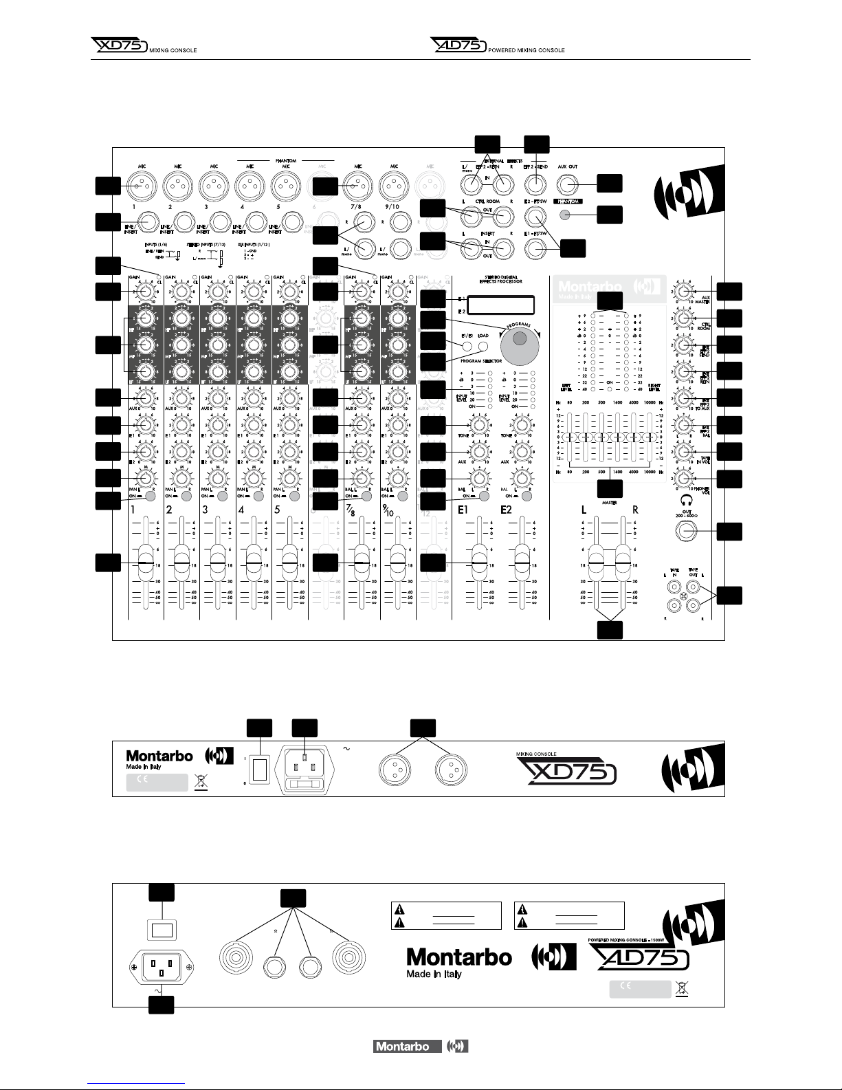
AD75 REAR PANEL
XD75 REAR PANEL
XD75 - AD75 FRONT PANEL
__________________________________________
__________________________________________
__________________________________________
__________________________________________
__________________________________________
__________________________________________
__________________________________________
__________________________________________
__________________________________________
__________________________________________
__________________________________________
INDICE
Controlli e connessioni 4 - 6
Equalizzatore grafico stereo 7
Doppio DSP multieffetto stereo 7 - 8
Importante ! 9
Appendice:
◗XD75 - AD75 Dati tecnici 18
◗XD75 Schema a blocchi 19
◗AD75 Schema a blocchi 20
◗XD75 - AD75 Connessioni 21 - 25
◗XD75 Esempi di collegamento 26
◗AD75 Esempi di collegamento 27
3
ITALIANO
Il lampo con la freccia inserito in un triangolo equilatero avvisa l'utilizzatore circa la presenza
di 'tensione pericolosa', senza isolamento, all'interno dell'apparecchio che potrebbe essere
sufficientemente alta da generare il rischio di scossa elettrica.
Il punto esclamativo inserito in un triangolo equilatero avvisa l'utilizzatore circa la presenza
di importanti istruzioni per l'utilizzo e per la manutenzione.
IMPORTANTE ! NORME DI SICUREZZA
ATTENZIONE !
Nell'interesse della propria e della altrui sicurezza, e per non
invalidare la garanzia, si raccomanda una attenta lettura di questa sezio-
ne prima di utilizzare il prodotto.
-Questo apparecchio è stato progettato e costruito per venire utilizzato come
mixer amplificato nel contesto tipico di un sistema di amplificazione sonora, e/o
di un sistema di registrazione sonora. L'utilizzo per scopi diversi da questi non è
contemplato dal costruttore, ed avviene pertanto sotto la diretta responsabilità
dell'utilizzatore/installatore.
- Questo apparecchio è conforme alla Classe di isolamento 1 (è necessario il
collegamento alla terra di protezione).
Per evitare il rischio di incendio e/o di folgorazione:
•Non esporre il prodotto alla pioggia, non utilizzarlo in presenza di elevata umi-
dità o vicino all'acqua. Non lasciare penetrare all'interno dell'apparecchio alcun
liquido, né alcun oggetto solido. In caso ciò avvenga, scollegare immediatamente
l'apparecchio dalla rete elettrica e rivolgersi ad un servizio di assistenza qualifi-
cato prima di adoperarlo nuovamente. Non appoggiare candele accese od altre
sorgenti di fiamma nuda sopra l'apparecchio.
•Prima di collegare l'apparecchio alla rete elettrica assicurarsi che la tensione
corrisponda a quella indicata sull'apparecchio stesso.
•Collegare questo apparecchio esclusivamente ad una presa di corrente dotata
di contatto di terra, rispondente alle norme di sicurezza vigenti, tramite il cavo
di alimentazione in dotazione. Nel caso in cui il cavo necessiti di sostituzione,
utilizzare esclusivamente un cavo di identiche caratteristiche.
•L'apparecchio è collegato alla rete anche quando l'interruttore di rete è in posi-
zione '0' (spento) e la spia luminosa è spenta. All'interno sono presenti potenziali
elettrici pericolosi. Prima di qualunque intervento di manutenzione, scollegare il
cavo di alimentazione dalla presa di rete.
•Non appoggiare alcun oggetto sul cavo di alimentazione. Non posarlo dove
possa costituire intralcio e causare inciampo. Non schiacciarlo e non calpestarlo.
•Installare questo apparecchio (AD75) prevedendo ampio spazio circostante per
un'abbondante circolazione d'aria, necessaria al raffreddamento. Non ostruire le
aperture o le prese d'aria presenti sull'apparecchio. Lasciare spazio sufficiente per
accedere alla presa di alimentazione elettrica e al connettore di rete sul pannello
posteriore.
•Prima di effettuare qualsiasi operazione di collegamento, assicurarsi che
l'interruttore di accensione dell'apparecchio sia in posizione '0'.
•Prima di effettuare qualsiasi spostamento del prodotto già installato o in
funzione, rimuovere tutti i cavi di collegamento.
•Per scollegare l'apparecchio dalla rete elettrica, non tirare mai lungo il cavo,
ma afferrarlo sempre per il connettore.
ATTENZIONE !
Questo appareccho non contiene parti interne destinate
all'intervento diretto da parte dell'utilizzatore.
Per evitare il rischio di incendio e/o folgorazione, non smontarlo e non
rimuovere alcun pannello. Per qualsiasi intervento di manutenzione
o riparazione, rivolgersi a Elettronica Montarbo srl e/o a personale
altamente qualificato specificamente segnalato da questa.
-Nel predisporre l'apparecchio all'utilizzo, assicurarsi che la forma e la portata
della superficie di appoggio siano idonee a sostenerlo.
-Per evitare urti riservate come luogo per l'istallazione del prodotto un'area
protetta inaccessibile a personale non qualificato. Qualora l'apparecchio venga
utilizzato in presenza di bambini e animali, si rende necessaria una strettissima
sorveglianza.
-Questo prodotto utilizzato insieme a cuffie o a casse acustiche è in grado di
generare pressioni acustiche molto elevate, pericolose per la salute del sistema
uditivo. Evitarne quindi l'utilizzo ad elevati o fastidiosi livelli acustici.
☛Non esporre i bambini a forti sorgenti sonore !
CONTENUTO DELL’IMBALLO
◗Mixer
◗Cavo di alimentazione
◗Manuale istruzioni
◗Certificato di garanzia
◗Dichiarazione di conformità CE
ITALIANO

4
CONTROLLI E CONNESSIONI
CANALE D'INGRESSO MONO
1 ➤GAIN: controlla il guadagno dello stadio di ingresso, permetten-
do il collegamento di sorgenti sia microfoniche che di linea aventi
segnali di uscita estremamente variabili. Come regola generale, al
fine di contenere al minimo il rumore, consigliamo di regolare il
GAIN al massimo livello possibile, evitando però che l'indicatore di
picco (CL) si illumini.
2 ➤H.F / M.F / L.F. Equalizzazione a 3 bande.
H.F: controlla il livello delle frequenze alte. La frequenza di
intervento è 10kHz, l'accentuazione/attenuazione 15dB.
M.F: controlla il livello delle frequenze medie. La frequenza di
intervento è 600Hz, l'accentuazione/attenuazione 15dB.
L.F: controlla il livello delle frequenze basse. La frequenza di
intervento è 80Hz, l'accentuazione/attenuazione 15dB.
N.B: Girando la manopola in senso orario si ottiene una accentuazione, in senso
antiorario una attenuazione. In posizione centrale la risposta è lineare.
3 ➤AUX: volume mandata ausiliaria (monitor).
Permette di regolare la quantità di segnale del canale nell'uscita
ausiliaria (dipende dai controlli di tono ed è indipendente dal
volume del canale).
4 ➤E1: volume mandata effetto 1 (dipende dai controlli di tono e
volume del canale). Permette di regolare la quantità di segnale del
canale da inviare al corrispondente effetto interno.
N.B: Sui canali dove non si vuole avere l'effetto interno E1, girare questa mano-
pola in senso completamente antiorario.
5 ➤E2: volume mandata effetto 2 (dipende dai controlli di tono e
volume del canale). Permette di regolare la quantità di segnale del
canale da inviare sia al corrispondente effetto interno che all'even-
tuale effetto esterno collegato alle prese send e return.
N.B: Sui canali dove non si vuole avere l'effetto interno E2 e neppure l'eventua-
le effetto esterno, girare questa manopola in senso completamente antiorario.
Se si vuole avere solamente l'effetto esterno, disattivare l'effetto interno E2.
6 ➤PAN: controllo di panorama. Permette di posizionare il segnale
(del canale) nell’immagine stereo inviandolo in quantità maggiore o
minore alle uscite master L ed R.
7 ➤ON: pulsante per attivare o disattivare il canale. Premendolo, il
segnale del canale viene inviato alle uscite master L/R, monitor AUX
ed effetti E1/E2. Si consiglia di tenere disinseriti i canali non utilizza-
ti, in modo da ridurre il rumore sulle uscite.
8 ➤VOLUME del canale.
9 ➤CL: indicatore LED di picco (clipping). Si illumina quando il livel-
lo del segnale è prossimo alla distorsione. Il segnale è controllato
contemporaneamente in due punti del canale: dopo l'amplificatore
di ingresso (micro e linea) e dopo l'equalizzatore.
Se il led CL si accende con continuità, è necessario ridurre il guada-
gno di ingresso (GAIN) o regolare diversamente l'equalizzazione del
canale riducendo l'esaltazione introdotta dai comandi HF, MF, LF.
10 ➤PHANTOM 48V DC: pulsante per inserire/disinserire l'alimen-
tazione phantom nei canali 4, 5, 6 (consente l'utilizzo di microfoni
a condensatore).
N.B: Questo pulsante va premuto con i volumi (dei canali 4, 5 e 6)
completamente abbassati.
lconnessioni:
11 ➤MIC: ingresso microfonico bilanciato con connettore XLR
(per il collegamento di microfoni).
12 ➤LINE/INSERT: ingresso linea sbilanciato con connettore jack
per il collegamento di strumenti e sorgenti di segnale ad alto livello.
Incorpora anche la connessione Insert, utilissima per collegare
apparecchi (effetti) esterni al singolo canale.
N.B:
Non collegare strumenti (o altre sorgenti ad alto livello) all'ingresso MIC !
(questo comporterebbe distorsione dovuta al segnale eccessivo).
Non collegare microfoni all'ingresso LINE ! (il segnale sarà di basso livello e
qualità).
CANALE D'INGRESSO STEREO
13 ➤GAIN: come nel canale mono.
14 ➤H.F / M.F / L.F: come nel canale mono.
15 ➤AUX: come nel canale mono.
16 ➤E1: come nel canale mono.
17 ➤E2: come nel canale mono.
18 ➤ BAL: controllo bilanciamento. Permette di regolare il livello
relativo destro/sinistro del segnale stereo del canale nelle uscite
master L/R. Se il canale viene usato in mono diventa un comando
PAN (panorama).
19 ➤ON: interruttore generale del canale. Come nel canale mono
20 ➤VOLUME del canale.
21 ➤CL: come nel canale mono.
lconnessioni:
22 ➤MIC: per dare al mixer una maggiore flessibilità di impiego,
anche i canali stereo dispongono di un ingresso microfonico
bilanciato (XLR) mono.
23 ➤L/R: ingressi linea sbilanciati jack per il collegamento di
strumenti stereo. Per collegamenti 'mono' utilizzare l'ingresso
'L / mono'.
ITALIANO

DOPPIO PROCESSORE MULTIEFFETTO STEREO
I due processori sono basati su un DSP a 56 bit con conversione
Delta/Sigma a24 bit. Ciascuno di essi offre 205 programmi di
grande qualità, prestazioni altamente professionali ed una estrema
facilità di utilizzo. Le dotazioni sono identiche per entrambi:
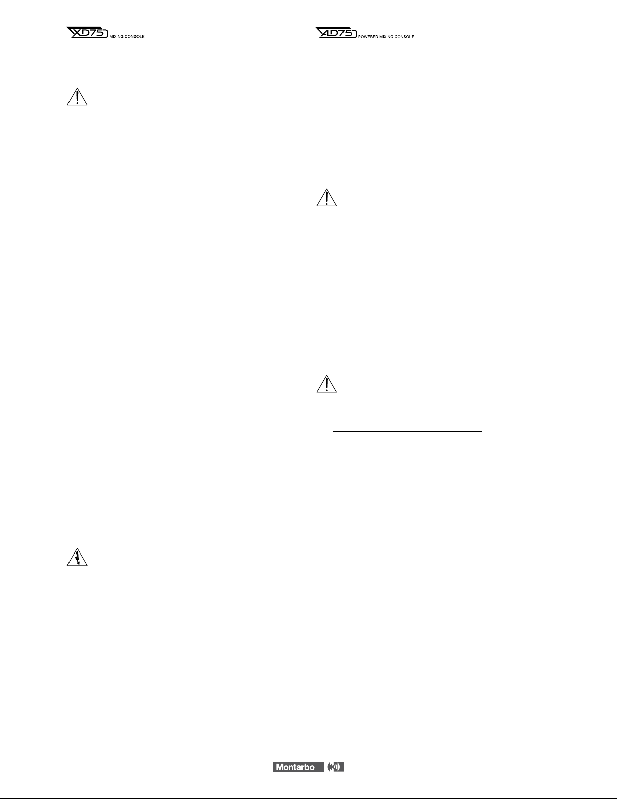
24 ➤DISPLAY a cristalli liquidi a due righe E1 ed E2. Indica i numeri
ed i nomi corrispondenti ai programmi selezionati.
25 ➤PULSANTE E1/E2. Permette di scegliere su quale gruppo
di effetti (E1 o E2, visualizzati sul display su due righe separate)
andare ad agire.
26 ➤PROGRAMS: manopola di selezione dei programmi.
Permette di selezionare uno dei 165 programmi disponibili nella
memoria di ognuno dei due effetti.
27 ➤LOAD: pulsante che permette di caricare e rendere attivo il
programma selezionato mediante la manopola PROGRAMS.
= indica che il programma selezionato è stato caricato.
= indica che il programma selezionato non è stato ancora
caricato.
28 ➤INPUT LEVEL: rampa a 5 LED per il controllo visivo del livello
di ingresso. Una buona regolazione delle mandate effetto (E1 ed
E2) sui singoli canali produrrà l'accensione dei LED verdi (e talvolta
del led giallo), mentre quello rosso dovrà lampeggiare solo occasio-
nalmente sui picchi di segnale.
+Se il LED rosso resta continuamente acceso è indice di saturazio-
ne ed è perciò necessario diminuire il volume delle mandate effetto
(E1ed E2) sui singoli canali.
29 ➤TONE: controllo di tono. Girando la manopola in senso orario
si produce una graduale attenuazione delle alte frequenze (in senso
completamente antiorario la risposta è lineare).
30 ➤AUX: mandata ausiliaria (monitor). Permette di regolare il
livello dell’effetto stereo sull'uscita Aux.
31 ➤BAL: bilanciamento. Permette di regolare il livello relativo
destro/sinistro del segnale stereo dell’effetto da inviare alle uscite
master L/R.
32 ➤ON: pulsante per attivare o disattivare l’effetto, con indicatore
LED rosso.
33 ➤Controllo di VOLUME.
lconnessioni:
34 ➤E1- E2 FT/SW: prese jack per footswitch. Consentono di
disattivare gli effetti mediante pedale. Ciò è possibile solo quando
il relativi pulsanti 'ON' sono premuti.
MANDATE E RITORNI EFFETTI ESTERNI
35 ➤EXT EFF 2 SEND: controllo di volume per la mandata effetti
esterni. Regola il livello di segnale presente sull'uscita EFF 2 SEND
ed è la miscelazione dei segnali inviati dalle mandate E2 dei singoli
canali.
36 ➤EXT EFF 2 RETN: controllo di volume per il ritorno effetti
esterni. Regola il livello di segnale del ritorno effetto esterno.
37 ➤EXT EFF 2 TO AUX: regola la quantità di effetto esterno da
inviare all'uscita AUX (monitor).
38 ➤EXT EFF 2 BAL: bilanciamento stereo dell’effetto esterno.
Permette di regolare il livello relativo destro/sinistro del segnale
stereo dell’effetto da inviare alle uscite master L ed R.
lconnessioni:
39 ➤EFF 2 SEND: uscita jack per la mandata effetto esterno.
40 ➤EFF 2 RETN L/R: 2 ingressi jack per il ritorno stereo dell'effetto.
• Sono utilizzabili anche come 2 ingressi linea extra.
nCollegare la presa EFF 2 SEND all'ingresso dell'effetto esterno.
nCollegare le uscite L ed R 'only effect' dell'effetto esterno alle
prese EFF 2 RETN L/R del ritorno effetti stereo.
• Per un effetto mono collegare l'ingresso
'L/mono' all'uscita 'only effect'
dell'effetto esterno.
nUtilizzare i controlli E2 di ogni canale per regolare la quantità di
segnale da inviare all'effetto esterno, il controllo EXT EFF 2 SEND
(35) per regolare la quantità di segnale da inviare all'uscita EFF 2
SEND, ed i controlli EXT EFF 2 RTN, EXT EFF 2 TO AUX e EXT EFF 2
BAL (36, 37, 38) per regolare il ritorno dell'effetto e le quantità
dello stesso da inviare all'uscita 'AUX OUT' ed ai master 'L/R'.
• Alla mandata E2 su ogni canale corrisponde anche l'effetto interno E2.
Per escludere quest'ultimo, disattivarlo mediante il comando 'on'.
N.B: Anzichè dell'uscita EFF
2 SEND, ci si può servire dell'uscita AUX OUT (se
non è impegnata per i monitor). In tal caso il segnale dell'effetto esterno sarebbe
regolabile mediante la mandata AUX di ogni canale e quindi totalmente
indipendente da quello dell'effetto interno E2.
☛
Figura 5pag. 25
CONTROLLI E CONNESSIONI
5
ITALIANO

52 ➤CTRL ROOM OUT L/R: uscite Control Room. Sono utilissime
in tante situazioni di lavoro (piano-bar, club, ristoranti, teatri ecc…)
per pilotare un secondo gruppo di casse amplificate con controllo
di livello indipendente dalmaster, creando così due zone di ascolto
distinte a volumi differenti oppure per avere nei monitor un control-
lo diretto del segnale di uscita. Nelle applicazioni in studio l'utilizzo
tipico è per i monitor di regia. Il volume di questa uscita viene
regolato mediante il comando CTRL ROOM indipendentemente dai
livelli delle uscite master L/R. Ognuna delle due uscite jack può
pilotare fino a 10 casse amplificate o finali di potenza.
☛
Figura 3pag. 24
53 ➤AUX OUT: uscita ausiliaria (monitor). Può pilotare fino a 10
casse monitor autoamplificate, collegate in parallelo.
n Collegare l'uscita AUX all'ingresso del monitor amplificato.
Regolare le mandate AUX di ogni canale ed il volume AUX MASTER.
☛
Figura 4pag. 24
N.B: Se non viene utilizzata per i monitor, può servire come mandata effetto
esterno (vedi fig. 5).
54 ➤TAPE IN/OUT L/R: ingressi e uscite (prese PIN-RCA) per il
collegamento di un registratore stereo.
n Collegare le prese TAPE OUT L/R del mixer agli ingressi (line in)
del registratore e le uscite (line out) del registratore alle prese
TAPE IN L/R del mixer. Se gli ingressi TAPE IN non vengono utilizzati,
si consiglia di tenere al minimo il volume TAPE IN VOL.
n Per riprodurre nastri già registrati porre il registratore in riprodu-
zione e regolare opportunamente il volume TAPE IN VOL del mixer
(ed i volumi di uscita del registratore, se presenti).
n Per registrare dall'impianto: porre il registratore in registrazione
e regolare opportunamente i volumi di ingresso del registratore.
Porre al minimo il volume di uscita del registratore. Nel caso in cui
il vostro registratore non disponga di questo controllo, scollegare i
cavetti dalle prese TAPE IN. Il segnale inviato al registratore non
dipende dalla regolazione dei volumi master L/R.
N.B: Gli ingressi TAPE IN L ed R sono normali ingressi di linea ed è perciò possibile
utilizzarli per collegare qualsiasi segnale di linea (ad esempio le uscite di un mixer,
strumenti, expander...).
☛
Figura 6pag. 25
55 ➤PHONES OUT: presa jack per cuffia stereo.
56 ➤XD75: Presa di rete a vaschetta con fusibile incorporato,
per il collegamento del cavo di alimentazione fornito di corredo.
NB: in caso di sostituzione dei fusibili esterni, utilizzare esclusivamente fusibili di
caratteristiche identiche (come riportato sull'apparecchio).
57 ➤AD75: Presa di rete a vaschetta, per il collegamento del cavo
di alimentazione fornito di corredo.
SEZIONE MASTER
41 ➤L/R MASTER: livelli generali per le uscite master L (sinistra)
ed R (destra).
42 ➤LEFT/RIGHT LEVEL: 2 rampe di LED a 12 segmenti che indica-
no il livello delle uscite master L ed R.
43 ➤EQUALIZZATORE grafico stereo a 6 bande.
44 ➤CTRL ROOM: controllo di livello per l'uscita stereo CTRL
ROOM.
45 ➤AUX MASTER: controlla il volume dell'uscita ausiliaria (moni-
tor). L'uscita master ausiliaria è la miscelazione di tutte le mandate
AUX dei singoli canali.
46 ➤TAPE IN VOL: volume dell’ingresso Tape.
47 ➤PHONES VOL: volume dell’uscita cuffia stereo.
48 ➤POWER: interruttore generale dell'apparecchio.
lconnessioni:
49 ➤XD75: LEFT/RIGHT OUTPUTS: uscite master L ed R per il
collegamento di finali di potenza o casse acustiche amplificate.
nCollegare le prese di uscita LEFT - RIGHT agli ingressi dei finali
di potenza o delle casse acustiche autoamplificate. Regolare i fader
dei volumi di ogni canale ed i controlli delle uscite master L (sinistra)
ed R (destra). Ogni uscita può pilotare fino a 10 casse acustiche
autoamplificate o finali di potenza collegati in parallelo.
N.B: Se si utilizzano dei connettori jack mono, le prese insert L/R possono fungere
da uscite master L/R. In tal caso le uscite XLR saranno scollegate.
☛
Figura 1A pag. 21
50 ➤AD75: SPEAKER OUTPUTS L/R: uscite dei due amplificatori
incorporati. L'impedenza minima per ogni amplificatore è di 4 Ohm.
nCollegare 1 o 2 casse acustiche da 8 Ohm per ogni uscita.
Mai fare funzionare gli amplificatori interni con carichi inferiori a
4Ohm ciascuno.
N.B: Ogni uscita dispone di prese Jack e Speakon (in parallelo), protezioni elettro-
niche, termiche, protezioni da corto circuito, relè per inserimento ritardato del
carico, autodiagnosi, ventilazione forzata.
☛
Figura 1B pag. 22
51 ➤INSERT L/R: prese jack stereo che permettono il collegamento
di apparecchiature ausiliarie esterne (ad esempio equalizzatori
grafici, limiter processore audio, ecc…) alle uscite master L/R.
Dipendono dalle regolazioni master L ed R.
Per l'inserzione di apparecchiature esterne vedere esempio di
collegamento.
☛
Figura 2A pag. 23
Nel mixer XD75 queste prese possono anche essere utilizzate
come normali uscite L/R usando jack mono standard. In questo caso
le uscite XLR sono disattivate.
☛
Figura 2A pag. 23
Nel mixer amplificato AD75 queste prese possono anche
essere utilizzate come uscite preamplificate del mixer per collegare
casse amplificate o amplificatori esterni.
n Per utilizzare le uscite linea del mixer senza escludere le uscite di
potenza prelevare il segnale dalle due prese insert mediante due
jack stereo, nei quali avrete precedentemente collegato l'anella
(RING) con la punta (TIP) cortocircuitandole, ed inviarlo agli ingressi
delle casse autoamplificate mediante dei jack mono.
☛
Figura 2B pag. 23
• Collegando alle prese insert dei jack mono le uscite degli amplificatori vengono
invece escluse.
6
CONTROLLI E CONNESSIONI
ITALIANO
7
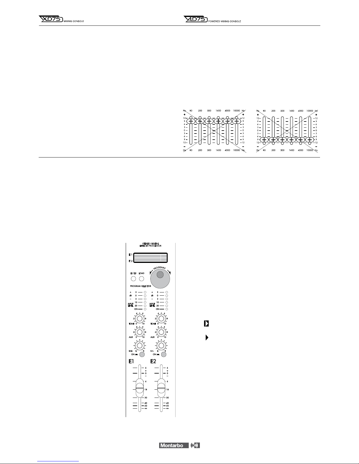
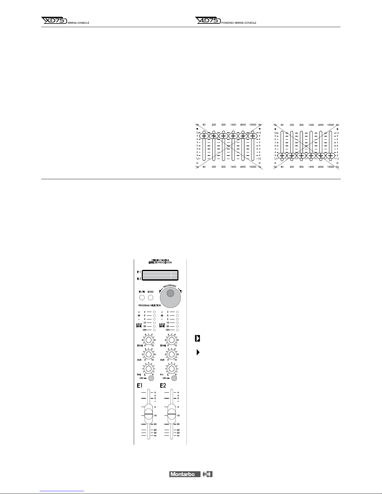
EQUALIZZATORE GRAFICO STEREO
L’equalizzatore, se convenientemente utilizzato, consente di correg-
gere gli effetti dell’ambiente sulla resa timbrica dell’impianto e di
ridurre fastidiosi rientri.
Per una corretta regolazione dell’equalizzatore, è opportuno tenere
presente i seguenti accorgimenti:
• Non usare regolazioni con tutti i cursori vicini ad uno degli estremi
della corsa. Questo comporta un inutile aumento di rumore ed una
riduzione di dinamica.
• Stabilite attentamente la posizione migliore per le casse e per i
microfoni. Ciò vi consentirà di ridurre al minimo i rientri ancor
prima di servirvi dell’equalizzatore, e di alterare il meno possibile
la timbrica del vostro programma musicale.
• Con i cursori dell'equalizzatore in posizione centrale (sullo '0')
agire sui controlli di tono di ogni canale per ottenere la tonalità
desiderata dai singoli microfoni o strumenti. Solo dopo avere
ottenuto una timbrica soddisfacente, regolare l'equalizzatore per
compensare le caratteristiche acustiche dell’ambiente.
In tal modo le differenze di resa tra un ambiente e l’altro possono
essere compensate utilizzando solo l’equalizzatore grafico, senza
necessità di grosse variazioni delle regolazioni dei canali.
DOPPIO PROCESSORE MULTIEFFETTO STEREO
Il doppio processore di effetti stereo incorporato è caratterizzato
da estrema facilità d’uso e da una scelta di programmi di grande
qualità, in linea con le tendenze più avanzate della produzione
musicale. All’accensione, il processore carica automaticamente
i programmi 19 e 61 (rispettivamente, delle famiglie HALO e
CHAMBER), una combinazione che offre ottime prestazioni con
i generi musicali più diversi.
REGOLAZIONE DEGLI EFFETTI
1– Attivate gli effetti E1 ed E2 premendo
i rispettivi tasti ON. L’accensione viene
visualizzata dai LED rossi.
2– Portare i fader degli effetti E1/E2 e
dei master L/R in posizione 0.
3– Sui canali di ingresso ai quali deside-
rate aggiungere gli effetti, regolate il fader
di volume ed i potenziometri E1 e E2.
4– Prestate attenzione ai livelli visualizzati
sulle barre LED:
• i LED rossi possono lampeggiare
saltuariamente.
• l'accensione continua dei LED rossi è
indice di segnali eccessivamente forti,
che possono dare origine a sgradevoli
distorsioni.
Ciò non è da imputarsi ad un difetto o
ad un limite della macchina, ma è comune
alla tecnologia dei processori digitali di
qualsiasi tipo.
Le barre LED servono appunto per
avvertire che è necessario ridurre i livelli
impostati con i potenziometri E1 o E2
sui canali.
ITALIANO
5– Se desiderate modificare il timbro dell'effetto, potete agire sul
controllo TONE per 'scurire' (ruotando la manopola in senso orario)
o 'schiarire' (ruotando la manopola in senso antiorario) la sonorità
del programma selezionato.
6– Assegnate i due effetti alle uscite master L ed R con i potenzio-
metri BAL e/o all'uscita Aux (per avere l’effetto sui monitor) con il
potenziometro AUX e regolate il volume dell'effetto con il fader.
7– Mediante il pulsante 'E1/E2' scegliete su quale gruppo di effetti
andare ad agire (il gruppo scelto verrà visualizzato sul display sulla
riga corrispondente). Selezionate ora il programma desiderato
mediante la manopola 'PROGRAMS'. Quindi per memorizzare il
programma appena selezionato premete il pulsante 'LOAD'.
La freccia indica che il programma selezionato è stato caricato
(memorizzato), ed è attivo.
La freccia indica che il programma selezionato non è ancora
stato caricato (memorizzato).
Ripetete la stessa operazione per il secondo gruppo di effetti.
nUtilizzate come riferimento la tabella riportata nella pagina ac-
canto per imparare a conoscere le sonorità dei diversi programmi.
nSperimentate liberamente tutti gli effetti, senza alcun timore,
fino a che non individuate i programmi che creano l’effetto più
gradevole al vostro orecchio.

8
ITALIANO
L’impiego di potenti DSP di ultima generazione ha permesso di
sviluppare nuovi algoritmi che ricreano, in modo realistico, le
dimensioni sonore dei più svariati ambienti e una serie inedita di
programmi, ottimizzati per esaltare le caratteristiche acustiche di
ogni singolo strumento.
Programmi e descrizione degli effetti
1
➔
5
EARLY
Le prime riflessioni del suono all’interno di un ambiente, prima che
cominci il vero e proprio riverbero.
6
➔
14
STEREO GEN
Generando brevi ritardi e sommandoli al segnale originale si percepisce
una maggiore apertura del suono monofonico.
15
➔
18
PING PONG
Suono ritardato (delay) che rimbalza da un canale all’altro, con ritardo
che cresce al crescere del numero del preset.
19
➔
23
HALO
Storico effetto che ripropone il famoso ‘eco a rullo’ Montarbo.
Consigliato per voci Vintage o Psyco.
24
➔
36
DELAY
Ritardi che aumentano al crescere del numero del preset e che
conferiscono una piacevole apertura al suono.
37
➔
40
DETUNE
Leggera alterazione nell’intonazione che arricchisce il suono senza
snaturarlo. Da provare su sezioni vocali tenute.
41
➔
45
FLANGER
Effetto molto incisivo che caratterizza fortemente il suono.
Sia i preset Mono che quelli Stereo rendono al meglio con strumenti
dal lungo Sustain.
46
➔
54
CHORUS
Modulando il ritardo e l’ampiezza del segnale trattato simula un vero
coro. I preset stereo danno un’apertura maggiore.
55
➔
57
AMBIENCE
Caratterizzato dalla predominanza di prime riflessioni seguite da una
riverberazione appena accennata. Simula un ambiente dalle dimensioni
contenute e dalle pareti riflettenti.
58
➔
61
CHAMBER
Ambiente leggermente più grande del precedente e con pareti che
assorbono maggiormente le riflessioni.
62
➔
66
ROOM
Dimensioni analoghe a quelle di una stanza normale. I preset alternano
pareti riflettenti ad altre assorbenti.
67
➔
73
HALL
Simulazione di un’ampia sala vuota, con pareti spoglie e piuttosto
riflettenti: il tipico salone per le feste.
74
➔
75
CATHEDRAL
Viene riprodotta la sensazione di spazio che si ha all’interno di un
ambiente molto grande, come una cattedrale.
76
➔
78
PLATE
Prende il nome dai primi generatori di riverbero elettromeccanici, che
usavano piastre di metallo per produrre un suono grande e brillante.
79
➔
81
PLATE DLY
Al suono prodotto dalla famiglia ‘plate’ viene aggiunto un pizzico
di eco per rendere il suono ancora più grande.
82
➔
85
BIG SPACE
Viene ricreato un ambiente vastissimo, surreale ma sicuramente
suggestivo.
86
➔
88
ECO REV
Uno degli effetti più usati: unisce la profondità dell’eco al calore del
riverbero. Generalmente utilizzato sulle voci dei cantanti, rappresenta
il classico punto di partenza.
89
➔
92
CONCERT
Viene ricreato lo spazio sonoro di una sala da concerto ampia, ma con
riflessioni controllate e dall'equilibrio tonale neutro.
93
➔
95
LIVE
Per provare la sensazione di cantare dal vivo all’aperto, sopra un grande
palco e davanti a migliaia di persone.
96
➔
99
GATE
La coda sonora del riverbero viene troncata bruscamente, rendendo il
suono molto particolare ed aggressivo.
100
➔1
34
VOX - FLUTE - TRUMPET - SAX - BRASS - KEYBRD - PIANO -
GTR - DRUM - TOMS - CYMB - HIHAT - KICK - SNARE - TOM
Questo gruppo di preset comprende degli effetti realizzati apposita-
mente per diversi strumenti, subito disponibili senza dover perdere
tempo con noiose programmazioni.
135
INSIDE A BOX
Simile al Room (62-66) ma l'ambiente ha dimensioni piccolissime.
136
LIVING ROOM
Come il precedente, ma le dimensioni dell'ambiente sono maggiori
(un tipico soggiorno).
137
➔
144
PTC REV
Al segnale trasposto come descritto nella famiglia ‘ pitch ’ viene
aggiunta una piacevole riverberazione.
145
➔
155
PITCH
Questi preset generano uno o più segnali alterati nell’intonazione ma
armonici con il segnale originale.
156
➔
165
DISTANCE
È un semplice ritardo del segnale di ingresso, utile nelle installazioni
con più linee di diffusori a distanza diversa dal pubblico.
Utilizzando le uscite AUX è possibile pilotare dei diffusori amplificati,
più vicini agli ascoltatori rispetto al sistema principale. Col crescere del
numero di preset il ritardo aumenta a passi di 5 metri.
* 166 ➔175
ECHO
Classico eco 'ribattuto' con ritardo crescente nei programmi superiori.
* 176 ➔185
ECHO + REVERB
Combinazione di eco e riverbero, di grande incisività, utilizzato in
tantissime produzioni musicali.
* 186 ➔195
VOICE REVERB
Serie di riverberi specifici per dare risalto alla voce.
* 196 ➔205
HALO + REVERB
Serie di combinazioni di halo e riverbero.
DOPPIO PROCESSORE MULTIEFFETTO STEREO
9
ITALIANO
IMPORTANTE!
CURA E MANUTENZIONE
• Questo prodotto è stato progettato per essere utilizzato in climi
tropicali e particolarmente caldi.
• Non porre sul mixer sorgenti di amme nude, quali candele
accese.
• Posizionare il mixer lontano da fonti di calore (caloriferi o qualsiasi
altro oggetto che produca calore).
• Evitate di esporre il mixer alla irradiazione solare diretta, ad
eccessive vibrazioni e a urti violenti.
• Evitate l’uso e il deposito in ambienti eccessivamente polverosi
o umidi: eviterete così cattivi funzionamenti e deterioramento
anticipato delle prestazioni.
• Nel caso in cui il mixer venga utilizzato all’aperto fare attenzione
a proteggerlo dalla pioggia.
• Evitate di utilizzare il mixer vicino a forti fonti di radiazioni
elettromagnetiche (video dei monitor, cavi elettrici di alta potenza):
ciò può provocare una diminuzione della qualità audio.
• Proteggere l'apparecchio dal rovesciamento accidentale di liquidi
o sostanze di qualsiasi tipo. In particolare nelle condizioni di utilizzo
tipiche, prestare la massima attenzione alla collocazione dell'appa-
recchio onde evitare che il pubblico, i musicisti, i tecnici o chicches-
sia possa poggiare bicchieri, tazze, contenitori di cibo o di bevande,
portacenere e sigarette accese sull'apparecchio.
• Abbiate cura dei cavi di collegamento, avvolgeteli evitando nodi
e torsioni.
• Non forzate i comandi (manopole, interruttori, cursori).
• Per rimuovere la polvere dal pannello usate un pennello o un
soffio d’aria. Non usate mai alcool, detergenti o solventi.
• Accertarsi che l'interruttore di rete sia in posizione '0' (spento)
prima di effettuare qualsiasi collegamento.
• All’interno dell’apparecchio possono essere presenti potenziali
elettrici pericolosi anche quando l’interruttore di rete è in posizione
'0' (spento) e la spia luminosa è spenta.
Prima di qualunque intervento di manutenzione, scollegare il cavo
di alimentazione dalla presa di rete
• In caso di necessità di assistenza, rivolgetevi alla Elettronica
Montarbo srl o a personale altamente qualificato.
COLLEGAMENTO ALLA RETE
• Accertarsi che l'interruttore di rete sia in posizione "0".
• Accertarsi che la tensione di alimentazione corrisponda a quella
indicata sul pannello.
• Collegare il cavo di alimentazione ad una presa di corrente dotata
di contatto di terra di sicura efficienza. Utilizzare solamente il cavo
di alimentazione fornito con l’apparecchio o un altro dotato di
contatto di terra e riportante i marchi di sicurezza applicabili nel
paese di impiego.
• Lasciare spazio sufficiente per accedere alla presa di alimentazione
elettrica e al connettore di rete sul pannello posteriore. All’interno
dell’apparecchio possono essere presenti potenziali elettrici pericolo-
si anche quando l’interruttore di rete è in posizione '0' (spento) e la
spia luminosa è spenta.
Prima di qualunque intervento di manutenzione, scollegare il cavo di
alimentazione dalla presa di rete.
INSTALLAZIONE ED USO
☛Utilizzare cavi di collegamento e connettori di qualità.
☛Utilizzare cavi schermati per i collegamenti agli ingressi
microfonici e linea, alle prese send/return, all'uscita aux, alle prese
tape in/out, alle prese insert L/R ed alle uscite control room.
☛Nel mixer XD75:utilizzare cavi schermati per il collegamento
di casse acustiche attive alle uscite master L/R.
☛Nel mixer amplificato AD75:utilizzare cavi non schermati di
adeguata sezione (min. 2,5mm2) per il collegamento di casse acusti-
che passive alle uscite amplificate L/R. Non utilizzare gli amplificatori
con un carico inferiore a 4 ohm ciascuno.
☛ Prima di accendere o spegnere l’apparecchio, chiudete (mettendo
al minimo i fader) le uscite master. Questo eviterà fastidiosi picchi di
segnale, che potrebbero danneggiare le casse acustiche.
COLLEGAMENTI E REGOLAZIONI INIZIALI
• Collegare le casse acustiche.
• Collegare i microfoni agli ingressi XLR e gli strumenti agli ingressi
jack. Non collegate i microfoni agli ingressi LINE!
• Prima di accendere l'apparecchio, mettere tutti i volumi al minimo.
• Dopo avere acceso l'apparecchio, regolare i controlli di guadagno
di ogni canale al minimo, i controlli di tono e panorama in posizione
centrale, le mandate ausiliarie e le mandate effetto al minimo.
• Per ottimizzare la dinamica di ogni canale, in base alle diverse fonti
di segnale, vi consigliamo di effettuare le seguenti operazioni:
- utilizzando il microfono (collegato alla presa XLR) nelle condizioni
di impiego a voi consuete, portare il comando GAIN in posizione
tale da fare illuminare il LED di picco,
- a tal punto diminuire il guadagno di quel tanto da fare spegnere
il LED di picco e regolare poi il fader del volume del canale.
Il LED di picco del canale è influenzato esclusivamente dal controllo
di guadagno e dai controlli di tono.
N.B: un canale per volta, effettuare questa operazione su tutti i canali utilizzando
le fonti di segnale per essi predisposte (voce femminile, voce maschile, strumenti)
e nelle condizioni di impiego il più possibile reali.
• Portare i fader dei volumi master L/R e degli effetti interni in
posizione vicina a '0' e il volume aux master in posizione centrale;
a questo punto alzare il volume di ogni singolo canale secondo le
proprie esigenze.
__________________________________________
__________________________________________
__________________________________________
__________________________________________
__________________________________________
__________________________________________
__________________________________________
__________________________________________
__________________________________________
__________________________________________
__________________________________________
WARNING !
In order to protect your own and others' safety and to avoid
invalidation of the warranty of this product, please read this
section carefully before operating this product.
-This product has been designed and manufactured for being operated as
powered mixing console in the applications tipical of a sound reinforcement
system or of a sound recording system. Operation for purposes and in applications
other than these has not been covered by the manufacturer in the design of the
product, and is therefore to be undertaken at end user's and/or installer's sole
risk and responsability.
- This unit conforms to Class 1 insulation, and for safe use it is required that the
protective earth contact is connected to a grounded (earthed) outlet.
TO AVOID THE RISK OF FIRE AND/OR ELECTRIC SHOCK:
•Never expose this product to rain or moisture, never use it in proximity of water
or on a wet surface. Never let any liquid, as well as any object, enter the product.
In case, immediately disconnect it from the mains supply and refer to servicing
before operating it again. Never place burning candles or other sources of open
flame on top of the device.
•Before connecting this product to the mains supply, always make sure that the
voltage on the mains outlet corresponds to that stated on the product.
•This product must be connected only to a grounded mains outlet complying
to the safety regulations in force via the supplied power cable. In case the power
cable needs to be substituted, use exclusively a cable of the same type and
characteristics.
•This device is connected to the power line even when the mains switch is in
the 0 (off) position and the power indicator is off. As long as it is plugged in
there are dangerous electrical potentials inside the device, so, before undertaking
any sort of maintenance work etc., always make sure it has been unplugged
from the mains socket.
•Never place any object on the power cable. Never lay the power cable on a
walkway where one could trip over it. Never press or pinch it.
•Never install the product (AD75) without providing adequate airflow to cool it.
Never obstruct the air intake openings on it. Leave enough room to get to the
mains power socket and the mains connector on the back panel.
•Always make sure the On/Off switch is in its Off position (0) before doing any
operation on the connections.
•Before attempting to move the product after it has been installed, remove
all the connections.
•To disconnect the power cable from the mains supply never pull the cable
directly instead, hold the body of the plug firmly and pull it gently from the
mains supply outlet.
CAUTION !
This product does not contain user serviceable parts.
To prevent fire and/or electrical shock, never disassemble it
and never remove its cover. For maintenance and servicing always
refer to the official Montarbo Distributor in your Country or
to qualified personnel specifically authorised by the Distributor.
-Before placing the product on a surface of any kind, always make sure that its
shape and load rating will safely match the product's size and weight.
-To avoid shocks, kicks, or whatever action, always reserve a protected area with
no access to unqualified personnel as installation site of the product.
In case the product is used near children and animals closest supervision is
necessary.
-This product in combination with headphones or speakers can generate very
high acoustic pressures which are dangerous for the hearing system.
Do not operate for a long period of time at a high or unconfortable volume level.
☛Never expose children to high sound sources.
ENGLISH
10
IMPORTANT ! SAFETY INSTRUCTIONS
The lighting flash with arrowhead symbol within an equilateral triangle, is intended to alert the
user to the presence of uninsulated "dangerous voltage" within the product's enclosure, that
may be of sufficient magnitude to constitute a risk of electric shock to humans.
The exclamation point within an equilateral triangle, is intended to alert the user to the
presence of important operating and maintenance (servicing) instructions.
PACKAGE CONTENTS
◗Mixing console
◗Power supply cable
◗Owner’s manual
◗Warranty certificate
◗CE declaration of conformity
ENGLISH
CONTENTS
Controls and connections 11 - 13
Stereo graphic equalizer 14
Dual stereo multieffects DSP 14 - 15
Important ! 16
Appendix:
◗XD75 - AD75 Technical specifications 18
◗XD75 Block diagram 19
◗AD75 Block diagram 20
◗XD75 - AD75 Connections 21 - 25
◗XD75
Connection examples
26
◗AD75
Connection examples
27

11
CONTROLS AND CONNECTIONS
MONO INPUT CHANNEL
1 ➤GAIN: adjust the gain (sensitivity) of the line and mic inputs,
allowing connections of signal sources (both line and mic level)
having a wide range of signal level. As a practical rule, the GAIN
control must be set to the maximum allowable level that will not
activate the peak level indicator (CL). This will maximize the signal
to noise ratio.
2 ➤H.F / M.F / L.F: 3-band Equalizer.
H.F.: adjusts the amount of high frequencies giving up to 15dB of
boost or cut at 10kHz.
M.F.: adjusts the amount of mid frequencies giving up to 15dB of
boost or cut at 600Hz.
L.F: adjusts the amount of low frequencies giving up to 15dB of
boost or cut at 80Hz.
Note: Turning the control clockwise increases the amount of high, mid or low
frequencies, counter-clockwise decreases it. The response is flat at the center
position.
3➤AUX: auxiliary send volume (post EQ, pre fader). It sets the
level of that input channel into the auxiliary output.
4➤E1: effect send 1 volume (post-fader and post EQ). It adjusts
the quantity of channel signal that is sent to the correspondent
built-in effect.
Note: On the channels where you don't want to have the internal effect E1,
turn this knob fully anticlockwise.
5 ➤E2: effect send 2 volume (post-fader and post EQ). It adjusts
the quantity of channel signal that is sent both to the correspondent
built-in effect E2 and to an external effect connected to the EFF 2
SEND socket.
Note: On the channels where you don't want to have neither the internal effect
E2 nor the external effect, turn this knob fully anticlockwise.
Should the external effect only be required, then turn off the E2 internal effect.
6➤PAN: this control allows to place the channel’s input signal
within the stereo image by assigning more or less of the signal
to the left or right master outputs.
7➤ON: channel's main on/off switch. When pushed, the channel's
signal is sent to the L/R master outputs, AUX output and E1/E2
effect sends. We suggest to switch all unused channels off, to
reduce the noise in the outputs.
8➤Channel VOLUME fader.
9➤CL: peak LED indicator. It lights when the signal level is
approaching the maximum (clipping) allowable level. The signal is
sampled in two points of the channel's signal path: after the input
amplifier (micro and line) and after the equalizer.
If the LED is continuously lighted, you must reduce the input GAIN
or modify the equalizer settings, reducing the boost introduced by
the EQ controls HF, MF and LF.
10 ➤PHANTOM 48V DC: pushbutton for switching on/off the
48V phantom power supply on channels 4, 5, 6 (the phantom
power supply allows use of condenser microphones).
Note: Push this button with the faders of channels 4, 5 and 6 are at their lowest
settings.
l
connections:
11 ➤MIC: balanced XLR microphone input (for microphones).
12 ➤LINE / INSERT: unbalanced jack line input (for instruments
and high level sources). Also usable as insert in/out socket.
Note:
Do not connect instruments or other high level sources to the MICRO inputs
(this will result in distortion due to excessive signal level).
Do not connect microphones to the LINE inputs (the resulting signal will be of
low level and low quality) .
STEREO INPUT CHANNEL
13 ➤GAIN: same as in the mono channel.
14 ➤H.F / M.F / L.F.: same as in the mono channel.
15 ➤AUX: same as in the mono channel.
16 ➤E1: same as in the mono channel.
17 ➤E2: same as in the mono channel.
18 ➤BAL: stereo balance. Allows to adjust the level of the input
signal in the left or right master outputs. If the channel is used as
a mono channel it becomes a PAN control.
19 ➤ON: channel's main on/off switch. Same as in the mono
channel.
20 ➤Channel VOLUME fader.
21 ➤CL: same as in the mono channel.
l
connections:
22 ➤MIC: balanced mono XLR input for mic-level signals.
23 ➤L/R: unbalanced jack line inputs for stereo instruments.
For 'mono' connections use 'L/mono' input.
ENGLISH

DUAL STEREO MULTIEFFECTS DSP
With 56-bit internal DSP and 24-bit Delta-Sigma conversion, the
two internal effects (205 programs each) provide high performance
digital audio processing combined with extremely easy operation.
24 ➤2-Line (E1 and E2) Liquid Crystal Display. Shows the numbers
and the names of the currently selected program.
25 ➤E1/E2 BUTTON: it allows operating on E1 or E2 lines on the
LCD (E1 and E2 are the two groups of effects).
26 ➤PROGRAMS KNOB: programs selection keys.
It allows selecting one of the 165 programs available for each of
the two effects (E1 and E2).
27 ➤LOAD BUTTON: allows loading and activating the program
selected with the PROGRAMS knob.
= shows that the selected program has been loaded.
= shows that the selected program has not been loaded yet.
28 ➤INPUT LEVEL: 5-segment input level LED indicator.
A good setting of the effect sends (E1 and E2) on each channel will
produce continuous lighting of the green LED segments, while the
red segment must flash only occasionally.
+If the red LED is continuously lighted it indicates signal overload
and it is necessary to reduce the effect send volumes (E1 and E2)
on individual channels.
29 ➤TONE control: Turning this control clockwise produces
a gradual decrease in high frequencies. Fully anticlockwise the
response is flat.
30 ➤AUX: auxiliary send. Allows to adjust the level of the stereo
effect in the Aux (monitor) output.
31 ➤BAL: balance. Allows to adjust the level of the stereo signal
in the L and R master outputs.
32 ➤ON: effect on/off button, with red LED indicator.
33 ➤VOLUME fader.
l
connections:
34 ➤E1 / E2 FT/SW: jack sockets for connection of remote
footswitches. They allow remote control enabling/disabling of
the built-in effect processors. This is possible only when the 'ON'
buttons are pushed.
EXTERNAL EFFECTS SENDS AND RETURNS
35 ➤EXT EFF 2 SEND: level control for the external effect send.
It is the mix of the signals sent from the E2 send volume on each
channel and sets the level of the signal appearing at the EFF 2 SEND
jack output.
36 ➤EXT EFF 2 RETN: level control for the external effect return.
Sets the signal level of the external effect return.
37 ➤EXT EFF 2 TO AUX: sets the level of the external effect to be
sent to the AUX output (monitor).
38 ➤EXT EFF 2 BAL: stereo balance of the external effect.
Allows to adjust the level of the stereo signal of the effect in the
L and R master outputs.
l
connections:
39 ➤EFF 2 SEND: jack output socket for the external effect send.
40 ➤EFF 2 RETN L/R: 2 jack inputs for the external effect return.
• They can also be used as 2 extra line inputs.
nConnect the EFF 2 SEND output to the input of the external effect.
nConnect the L and R outputs of the stereo external effect to the
L and R EFF 2 RETN inputs of the stereo effects return.
•For a mono effect connect its 'only effect' output to the 'L / mono' socket.
nUse the E2 controls on each channel to determine the quantity
of channel's signal to be sent to the external effect, the EXT EFF 2
SEND control (35) to determine the quantity of signal to be sent to
the EFF 2 SEND, and the EXT EFF 2 RTN, EXT EFF 2 TO AUX and EXT
EFF 2 BAL (36, 37, 38) controls to adjust the effect return level in
the 'AUX OUT' and master 'L/R' output.
• The E2 control on each channel is also the effect send for the 2nd
internal effect.
To exclude E2 internal effect, turn it off by releasing its 'on' button.
Note: The AUX output (if not used as monitor output) can be used in place of
the EFF
2 output. In this case the signal of the external effect is adjusted by
means of the AUX send control on each channel and it is thus fully independent
of the internal E2 signal.
☛
see fig. 5page 25
CONTROLS AND CONNECTIONS
12
ENGLISH

13
MASTER SECTION:
41 ➤L/R MASTER: volume faders for the left and right master
outputs.
42 ➤LEFT/RIGHT LEVEL: two 12 segment LED arrays give
istantaneous reading of L and R outputs levels.
43 ➤6-band stereo graphic EQUALIZER.
44 ➤CTRL ROOM: level control for the control room stereo output.
45 ➤AUX MASTER: volume control for the auxiliary output.
The auxiliary master output is the mix of the individual channel's
AUX sends.
46 ➤TAPE IN VOL: sets the level of the signal from the 'Tape in'
socket of the mixer.
47 ➤PHONES VOL: level control for the stereo phones output.
48 ➤POWER: mains power switch.
l
connections:
49 ➤XD75 LEFT/RIGHT OUTPUTS: L/R master outputs for the
connection of power amplifiers or active speaker enclosures.
nConnect the L/R master outputs to the inputs of the self-powered
speaker enclosures or to the inputs of the power amplifiers.
Adjust the volume fader on each channel as well as the L/R master
volume faders. Each output can drive up to 10 parallel connected
active speaker enclosures or power amplifiers.
Note: Using standard mono jack plugs the L/R insert sockets may be used as
normal jack outputs. In this case the XLR outputs are disconnected.
☛see fig. 1A page 21
50 ➤AD75 L/R SPEAKER OUTPUTS: output sockets for the internal
power amplifiers. Minimum load impedance for each amplifier is
4 Ohms.
nConnect one or two 8 Ohms speakers for each output. Never
operate the internal power amplifiers with loads below 4 Ohms
each.
Note: Each output is fitted with 2 jack and 2 Speakon sockets (parellel
connected) and features electronic protections, delayed power-up sequence,
automatic troubleshooting and forced cooling.
☛
see fig. 1B page 22
51 ➤L/R INSERT: these stereo jack sockets (post-master faders)
allow the connection of external auxiliary equipment such as stereo
equalizer, limiter, audio processor,etc… to the master outputs.
See connection example.
☛
see fig. 2A page 23
In the mixer XD75 they may also be used as normal jack outputs
(using standard mono jack plugs). In this case the XLR outputs are
disconnected. ☛see fig. 2A page 23
In the powered mixer AD75 these sockets can also be used as
preamp-outputs for connecting powered speakers or external
power amplifiers.
nIt is possible to use the line and power outputs at the same time.
Take out the signal from the insert sockets by means of two stereo
jack plugs, in which you have previously joined the RING with the
TIP (see example in page 41) and send it to the inputs of the active
speakers by means of mono jack plugs.
☛
see fig. 2B page 23
• If you plug mono jack into the stereo insert sockets, the power outputs are
automatically excluded.
CONTROLS AND CONNECTIONS
52 ➤L/R CTRL ROOM OUT: the Control Room outputs provide
a duplication of the master outputs signal.
To feed your nearfield monitors while playing or recording or to
feed a separate, second PA while performing live to allow different
audiences listen at different sound levels (louder on the dancefloor
near you, softer at the tables where people’s talking).
The output level is adjusted by means of the CTRL ROOM level
control, which is independent from the L/R master outputs volume
levels. Each of the two outputs can drive up to 10 active speaker
enclosures or power amplifiers.
☛
see fig. 3page 24
53 ➤AUX OUT: auxiliary output (monitor). It can drive up to 10
parallel connected powered monitors.
nConnect the AUX socket to the input of the self-powered stage
monitor.
☛
see fig. 4page 24
• If it is not required as monitor output, it can be used as effect send (see fig. 5).
54 ➤L/R TAPE IN/OUT: PIN in-out sockets. They allow connection
to stereo tape recorder.
nConnect the L/R TAPE OUT sockets to the inputs of the tape
recorder (line in) and the outputs of the tape recorder (line out)
to the L/R TAPE IN sockets of the mixer. If the TAPE IN inputs are
not used, it is suggested to keep the TAPE IN volume control fully
closed, to keep output noise to the minimum.
nFor playback: switch the recorder to play and adjust the TAPE IN
VOL control on the mixer (and the output volumes of the tape
recorder, if available).
nFor recording: switch the recorder to the 'record' mode and
adjust the input volume of the tape recorder. Set the output
volume control of the tape recorder to its lowest setting. In case
your tape recorder has no output volume control, disconnect the
cables from the TAPE IN sockets. The signal sent to the tape
recorder is unaffected by the L/R master faders settings.
Note: The L/R Tape inputs accept any line signal. You can thus use them as 2
extra line inputs to connect instruments, expanders or the L/R outputs of a mixer.
☛
see fig. 6page 25
55 ➤PHONES OUT: output for stereo headphones.
56 ➤XD75: I.E.C power supply socket and mains fuse.
Note: In case the external fuse needs replacement, substitute it only with one
of the same type and rating, as stated on the product.
57 ➤AD75: I.E.C power supply socket.
ENGLISH
STEREO GRAPHIC EQUALIZER
Careful use of the graphic equalizer can help the overall system
sound more natural in less than perfect acoustic environments and
allows to reduce feedback. For a proper setting of the controls of
the graphic equalizer consider the following:
• Avoid settings with all sliders up or all sliders down. This would
involve a useless increase in noise or a reduction of dynamic range.
• Choose carefully the placement of loudspeakers and microphones
to minimize feedback before using the equalizer, in order to get
the most volume before feedback is heard. Otherwise you risk
removing significant amounts of your program material and altering
too much your sounds.
• With the graphic equalizer’s controls set to the zero mark
(centered) adjust the tone controls of each channel until you get
the tonal color you want for each microphone or instrument.
Once you have adjusted the tone controls of each channel, start
adjusting the controls of the graphic equalizer to compensate for
the acoustic environment and speaker placement.
This will allow you to compensate for different acoustic
environments acting only on the equalizer’s setting with no need
to modify the tone controls settings of each channel.
14
DUAL STEREO MULTIEFFECTS PROCESSOR
ENGLISH
The built-in effects processor has been designed for maximum ease
of use. It sports a wide range of high quality programs, all carefully
tailored to today’s music production requirements. At startup, programs
19 and 61 are auto-loaded: these HALO and CHAMBER effects
provide good results in the most different music styles, so you will
maybe want to use them as general purpose effects.
EFFECTS SETUP
1– Switch E1 and E2 to operation by
pushing their ON buttons.
A red LED lights up on each processor to
signal its status.
2– Bring the effects faders E1/E2 and the
L/R master faders near to the '0' position
on their scale.
3– Set the channel volume and the
effects sends levels with E1 and E2
controls on the input channels you wish
to add effects to.
4– Carefully check the input levels on
the LED bargraphs of both processors:
• the red LEDs should blink occasionally
• if the red LEDs are constantly lit, you
could suffer severe distortion on the
effect signal. This isn’t due to the
processor itself, rather it is common on
digital processors of any price because
of the digital technology itself.
In case, reduce the levels of the E1 and E2
controls on the input channels until the
red LEDs of LED bargraph light up only
on loudest peaks.
5– You can alter the effect timbre with the TONE control on the
effects processor: turn it counter-clockwise to 'brighten' the effects,
or clockwise to 'darken' them.
6– Route the effects to the main outputs with the BAL control,
and/or to the stage monitors with the AUX control, then set their
volume faders at the desired levels.
7– Select the group of effects (E1 or E2) on which you want to
operate with the E1/E2 button. The selected group of programs will
be shown on the correspondent line on the display. Now select the
program, you wish to use, with the
knob PROGRAMS
.
Use the button LOAD to load the selected program.
= shows that the selected program has been loaded and is
active.
= shows that the selected program has not been loaded yet.
nUse the chart on the next page as a reference to recognize the
programs.
n Feel free to experiment with any program until you get the sound
that most satisfies your taste.

15
ENGLISH
New algorithms, running on powerful, latest generation's DSP, emulate
the acoustic characters of various ambient, an a new series of programs
is available to enhance the acoustic character of various instruments.
Programs and effects description
1
➔
5
EARLY
Generates the initial part of room reverberation, without the decay of
the reverberant field.
6
➔
14
STEREO GEN
Generates a pseudo-stereo effect out of mono sources by adding short
delays to the signal.
15
➔
18
PING PONG
A delayed sound is bounced between the stereo channels. The delay
time increases with the preset number.
19
➔
23
HALO
A digital recreation of the tried and proven Montarbo magnetic memo-
ry effect. Suggested for Vintage or Psyco voices.
24
➔
36
DELAY
A simple delay, with the delay time increasing with the preset number.
It will add a pleasant openness to any sound.
37
➔
40
DETUNE
Slightly changes the tuning of the source. It enriches the sound without
rendering it "unnatural". Test it on sustained vocals.
41
➔
45
FLANGER
A powerful effect that gives a strong character to the sound. Both
Stereo and Mono presets will perform best with long sustained instru-
ments.
46
➔
54
CHORUS
A choir effect is simulated by modulating both delay and amplitude.
Stereo presets result in a "wider" stage.
55
➔
57
AMBIENCE
It emulates a small room, with reflecting surfaces. Early reflections
predominate, with a slight reverberation.
58
➔
61
CHAMBER
A room slightly larger than the former, with more sound adsorbing
surfaces.
62
➔
66
ROOM
The size is that of a living room. The presets alternate between reflec-
ting and adsorbing surfaces.
67
➔
73
HALL
A large, empty room, with mostly reflecting, naked walls: the typical
party hall.
74
➔
75
CATHEDRAL
A very large room, such a church or a cathedral.
76
➔
78
PLATE
It recreates the sound of the first electro-mechanical reverberation
devices, that used metal plates for a large and brilliant sound.
79
➔
81
PLATE DLY
A slight echo is added to the Plate effect, giving an even larger sound.
82
➔
85
BIG SPACE
A really spacious room. The sound is unnatural but really evocative.
86
➔
88
ECO REV
One of the most commonly used effects: it blends the depth of the
echo with the warmth of the reverb. Usually applied to vocals, it is the
classical starting point for testing effects.
89
➔
92
CONCERT
The acoustic space of a large concert hall with controlled reflections
and a neutral tonal character.
93
➔
95
LIVE
It will give you the sensation of a live concert in an open space, on a
large stage in front of thousands of listeners.
96
➔
99
GATE
The reverberation decay is suddenly muted, giving the sound an aggres-
sive character.
100
➔1
34
VOX - FLUTE - TRUMPET - SAX - BRASS - KEYBRD - PIANO -
GTR - DRUM - TOMS - CYMB - HIHAT - KICK - SNARE - TOM
This preset group includes custom-made effects for specific instru-
ments, readily available without time-consuming programming.
135
INSIDE A BOX
Similar to Room (63-66), but the room's size is very small.
136
LIVING ROOM
Similar to the former, but the room's size is larger (a typical living
room).
137
➔
144
PTC REV
A pleasant reverberation is added to the pitch transposed signal descri-
bed below.
145
➔
155
PITCH
These presets generate signals that are harmonic with the source, but
transposed in terms of pitch.
156
➔
165
DISTANCE
It is a simple delay of the input signal, useful in installations with many
loudspeakers at different distances from the listeners. With the AUX
outputs it is possible to drive other active speakers placed nearer the
listeners than the main speakers. The delay time increases with the
preset number at 5 meter increments.
* 166 ➔175
ECHO
Classic multiplex effect. Delay time increases with program number.
* 176 ➔185
ECHO + REVERB
Delay and reverb blended together make for the impressive effect you
can listen on most contemporary productions.
* 186 ➔195
VOICE REVERB
Reverbs specially tailored to enhance vocals’ character.
* 196 ➔205
HALO + REVERB
Halo and reverb effects blended together.
DUAL STEREO MULTIEFFECTS PROCESSOR

16
ENGLISH
IMPORTANT!
CARE AND MAINTENANCE
• This product has been designed for use in tropical climates and
particularly warm weather conditions.
• Never place burning candles or other sources of open ame on
top of the device.
• Never expose the mixer to heat sources such as radiators or other
products that produce heat.
• Never expose the mixer to direct sunlight, excessive vibrations
or mechanical shocks.
• Avoid operating and storing the mixer in damp or dusty places:
this will avoid malfunctions and premature degrading of
specifications.
• When setting up the mixer up outdoors, be sure to protect it
against rain.
• Avoid using the mixer close to strong sources of electromagnetic
interferences (e.g. video monitors, high power electrical cabling).
This may lead to degradation of audio quality.
• Care should be taken so that objects do not fall and liquids are
not spilled into the mixer. In public event don't let people, musicians,
technicians or anyone put glasses, cups, ashtrays and cigarettes on
the mixer.
• Take care of the connection cables, always coil them avoiding
knots and twists.
• Never apply excessive force to the controls (knobs, sliders,
pushbuttons).
• Use a soft brush or a jet of air to clean the panel.
Do not use alcohol, solvents or detergents.
• Make sure the mains power switch is off ('0') before starting
any connection.
• As long as it is plugged in there can be dangerous electrical
potentials inside the device, so, before undertaking any sort of
maintenance work etc., always make sure it has been unplugged
from the mains socket.
• If service is needed, refer to qualified service personnel only
or to the Montarbo distributor in your country.
MAINS POWER CONNECTION
• Make sure the mains power switch is off ('0').
• Check that mains voltage corresponds to the voltage indicated
on the panel, under the mains socket.
• Use only the factory supplied mains cable or, if a different plug
style is needed, a suitable cable with a ground connection and
marked with the safety approvals valid in the country of use.
• Leave enough room to get to the mains power socket and the
mains connector on the back panel. As long as it is plugged in there
can be dangerous electrical potentials inside the device, even when
the mains switch is in the '0' (off) position and the power indicator
is off so, before undertaking any sort of maintenance work etc.,
always make sure it has been unplugged from the mains socket.
INSTALLATION AND USE
☛Always use quality cables and connectors.
☛Use shielded cables for your connections to the micro and line
inputs, to the send/return sockets, to the aux output, to the tape
in/out and L/R insert sockets and to the control room outputs.
☛In the mixer XD75 use shielded cables for the connection of
active speaker enclosures to the L/R master outputs of the mixer.
☛In the powered mixer AD75 use unshielded cables for the
connection of passive speaker enclosures to the powered outputs
of the mixer. Never operate the internal power amplifiers with loads
of less than 4 ohm each.
☛Before switching on or off the mixer, 'close' (set to minimum the
outputs faders) the master outputs. This will avoid switching noises
that may cause damages to loudspeakers.
PRELIMINARY CONNECTIONS AND SETTINGS
• Connect the passive speaker enclosures.
• Connect the microphones to the XLR inputs and the instruments
to the jack inputs.
Do not connect microphones to the LINE inputs
• Before turning on the mixer, set the channel volume faders and
the master volume faders to their lowest settings.
• Switch on the unit and turn the gain controls to their lowest
settings, the tone controls and panpots to the middle position, and
the auxiliary and effect sends anti-clockwise to their lowest settings.
• To optimize dynamics of each channel according to the
various signal sources, proceed as follows:
- using a microphone (connected to the XLR mic input) in
conditions typical of the intended use, set the GAIN control
so as to cause the Peak LED to illuminate;
- now reduce the GAIN just enough until the peak LED switches
off and adjust the volume.
The channel's peak LED is affected only by the GAIN control and
the TONE controls.
Note: Repeat the above procedure for all the channels, one at a time, using the
signal source assigned to that channel and simulating real operating conditions
as closely as possible.
• Set the volume faders of the L/R master outputs and of the
internal effects near to the '0' setting and the aux volume control
to the middle position, and now adjust the volume (7) of each
channel according to your requirements .

17
__________________________________________
__________________________________________
__________________________________________
__________________________________________
__________________________________________
Technical Specifications 18
Dati tecnici, Technische Daten,
Spécifications techniques, Datos técnicos
XD75 - AD75 Block diagram 19 - 20
Schema a blocchi, Blockdiagramm,
Schéma, Esquema de bloques
Connections 21 - 25
Connessioni, Anschlußbeispiele,
Connections, Conexiones
XD75 - AD75 Connection examples 26 - 27
Esempi di collegamento, Anschlußbeispiele,
Exemples de branchement, Ejemplos de conexion
APPENDIX
APPENDIX

18
TECHNICAL SPECIFICATIONS
TECHNICAL SPECIFICATIONS XD75 AD75
Mono Input channels: 6 6
micro (sensitivity / impedance) - 60dB / 2,2 kOhms - 60dB / 2,2 kOhms
line (sensitivity / impedance) - 30dB / 33 kOhms - 30dB / 33 kOhms
phantom power supply (on ch. 4, 5, 6) 48 V 48 V
channel gain control range 50dB 50dB
equivalent input noise - 128dB - 128dB
equalization H.F ±15dB@10kHz shelving H.F ±15dB@10kHz shelving
M.F ±15dB@600Hz
peaking
M.F ±15dB@600Hz
peaking
L.F ±15dB@80Hz shelving L.F ±15dB@80Hz shelving
Stereo Input channels: 3 3
micro (sensitivity / impedance) - 60dB / 2,2 kOhms - 60dB / 2,2 kOhms
line L/R (sensitivity / impedance) - 48dB / 33kOhms - 48dB / 33kOhms
channel gain control range 30dB 30dB
equivalent input noise - 128dB - 128dB
equalization H.F ±15dB@10kHz
shelving
H.F ±15dB@10kHz
shelving
M.F ±15dB@600Hz
peaking
M.F ±15dB@600Hz
peaking
L.F ±15dB@80Hz
shelving
L.F ±15dB@80Hz
shelving
Dual multieffect DSP 2 x 165 stereo effects 2 x 165 stereo effects
A-D and D-A conversion 24 bit Delta/Sigma 24 bit Delta/Sigma
DSP 56 bit 56 bit
bandwidth 40Hz ÷ 15kHz 40Hz ÷ 15kHz
THD < 0,1% < 0,1%
S.N.R > 98dB > 98dB
External effect send:
nominal level -10dB -10dB
impedance 600 Ohms 600 Ohms
max level + 20dB + 20dB
External effect return:
nominal level - 10dB - 10dB
impedance 10kOhms 10kOhms
max level + 20dB + 20dB
Aux Output
nominal level 0dB 0dB
max level + 20dB + 20dB
min. load impedance 600 Ohms 600 Ohms
L-R Master, C. Room outputs:
nominal level 0dB 0dB
impedance 100 Ohms 100 Ohms
max level + 20dB + 20dB
min load impedance 600 Ohms 600 Ohms
frequency response 25Hz÷20kHz (+0 / -2dB) 25Hz÷20kHz (+0 / -2dB)
THD < 0,03% < 0,03%
S.N.R > 80dB > 80dB
L-R Insert Outputs: nom. level / max. level 0dB / + 20dB 0dB / + 20dB
Tape in: nominal level - 10dB - 10dB
Tape out: nominal level - 10dB - 10dB
Headphones: load impedance 200 ÷ 600 Ohms 200 ÷ 600 Ohms
Dimensions / Weight: 49,5 x 10 x 41 cm / 6,5 Kg 49,5 x 16 x 41 cm / 10 Kg
Amplifiers (processor controlled) 2 digital amplifiers
total output power (W EIAJ) 750 +750 W / 4 Ohms
370 + 370 W / 8 Ohms
protections thermal, electronic short circuit protections,
delayed power-up sequence, forced cooling,
automatic trouble-shooting.
APPENDIX
MIXER SECTION
AMPS SECTION
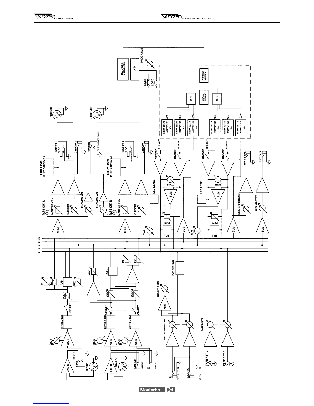
XD75 BLOCK DIAGRAM
APPENDIX
19

AD75 BLOCK DIAGRAM
20
APPENDIX
This manual suits for next models
1
Table of contents
Languages:
Other Montarbo Music Mixer manuals


