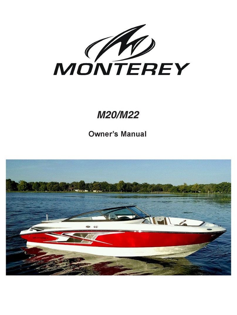
Monterey Boats 242 CR User manual

CRUISERS
OWNER’S MANUAL
242 CR
262 CR
282 CR
298 S
302 CR
322 CR

WELCOME TO THE
WORLD OF MONTEREY!
The family at Monterey wishes to thank you for choosing us to be your family's boat builder. It is a
responsibility not taken lightly and that is why each Monterey is built to the standards set forth by the
United States Coast Guard, the National Marine Manufacturers Association, and the American Boat and
Yacht Council.
This owner's manual will introduce you to the things that make your Monterey unique to the boating world.
To assist you in becoming familiar with your boat, please take the time to review this manual and the
information in your owner's packet.
Because we at Monterey continue to make product improvements through out the year some of the
equipment descriptions may be different than what appears in your manual. In these cases, please refer
to your owner's packet.
A plan for routine periodic maintenance and attention to safety inspections will protect your Monterey in
the years to come. If you have further questions, please consult your authorized dealer or contact the
Monterey Customer Service Department at (352)529-9181.
Have a safe boating day!
DATE PURCHASED ________________________________________________________________
DEALER/PHONE NUMBER __________________________________________________________
BOAT MODEL______________________________________________________________________
HULL ID NUMBER __________________________________________________________________
TRAILER ID NUMBER ______________________________________________________________
ENGINE MAKE/MODEL ______________________________________________________________
ENGINE #1 SERIAL NUMBER ________________________________________________________
ENGINE #2 SERIAL NUMBER ________________________________________________________
DRIVE MAKE/MODEL ______________________________________________________________
DRIVE #1 SERIAL NUMBER __________________________________________________________
DRIVE #2 SERIAL NUMBER __________________________________________________________

i-1
TABLE OF CONTENTS
Page
M INTRODUCTION ...................................... M-1
Specifications.............................................M-2
Special Gas Precautions ...........................M-2
Fire Extinguishing System.........................M-3
Troubleshooting .........................................M-3
Generator Set............................................M-8
Air Conditioning ........................................M-10
A.C. Wiring Diagrams ...............................M-11
Electrical Schematics................................M-14
298S Information ......................................M-32
1 BOATING SAFETY .................................. 1-1
Boating Regulations .................................. 1-2
Boater Responsibilities ............................. 1-2
Required Safety Equipment ...................... 1-3
Emergencies ............................................. 1-7
Hazardous Conditions .............................. 1-8
Operation By Minors ................................ 1-10
Passenger Safety ..................................... 1-11
Water Sports ............................................ 1-11
General Precautions ................................ 1-12
2 BASIC RULES OF THE ROAD ................ 2-1
Aids to Navigation ..................................... 2-1
Right-of-Way ............................................. 2-4
3 CONTROLS AND INDICATORS .............. 3-1
Shift/Throttle Control ................................. 3-1
Instruments ............................................... 3-2
Switches ................................................... 3-4
Steering System ........................................ 3-8
4 OPERATION ............................................. 4-1
Fueling ...................................................... 4-1
Starting ..................................................... 4-2
Shifting/Running ....................................... 4-4
Warning Alarm .......................................... 4-4
Steering Controls ...................................... 4-5
Stopping .................................................... 4-5
Docking ..................................................... 4-6
Boat Trim ................................................... 4-7
Drive Trim Angle ....................................... 4-7
Page
5 GETTING UNDERWAY ............................ 5-1
Safety Checklist ........................................ 5-1
Safety Equipment ..................................... 5-2
Boarding ................................................... 5-2
6 RUNNING ................................................. 6-1
Maneuvering Techniques .......................... 6-1
Salt Water ................................................. 6-2
Freezing Temperatures ............................. 6-3
Towing Procedure ..................................... 6-3
Anchoring ................................................. 6-4
Performance Boating ................................ 6-5
Propellers ................................................. 6-6
7 CARE AND MAINTENANCE ................... 7-1
Electrical ................................................... 7-1
Fuel System .............................................. 7-3
Steering System ....................................... 7-3
Corrosion Protection ................................. 7-3
General Maintenance ............................... 7-4
8 TROUBLESHOOTING ............................. 8-1
Trouble Check Chart ................................. 8-1
9 STORAGE ................................................ 9-1
10 TRAILERING .......................................... 10-1
Classifications ......................................... 10-1
Trailer Components ................................. 10-2
Safety Chains ......................................... 10-2
Trailering Checklist ................................. 10-3
Backing Up Trailers ................................. 10-4
Launching ............................................... 10-5
Loading ................................................... 10-5
Slinging/Lifting ........................................ 10-6
11 SHIP SYSTEMS ..................................... 11-1
Electrical Systems .................................. 11-1
Water Systems ....................................... 11-8
Hot Water Heater .................................. 11-16
Sanitizing The Fresh Water System ..... 11-17
Sample Float Plan ................................ 11-22
12 GLOSSARY OF TERMS ........................ 12-1

M-1
INTRODUCTION
This manual is designed to give you a basic understanding of your Monterey boat and some of the
responsibilities that go along with owning/operating a boat. Of primary importance is the
owner’s/operator’s responsibility for safety. Read this manual and all other information supplied with your
boat before taking to the water and be sure that all other operators do the same.
This manual is not intended to be the final authority, but rather a general guide for operation. If the
information contained in this manual should conflict with that given in the manufacturer’s information, the
manufacturer’s information shall take precedence.
As part of your warranty responsibilities, you must register your Monterey boat within 10 days of purchase
and perform periodic maintenance/ inspections as outlined in this manual and other information supplied
in the owner’s packet.
The descriptions and specifications contained in this manual were in effect at the time of printing.
Monterey Boats reserves the right to discontinue models at anytime, without notice and without incurring
obligation. The equipment and features described within this manual may not be identified as either
standard or optional. Refer to the current price sheet for correct vendor supplied options.
This section contains specific information about your Monterey boat that is different or not covered
elsewhere in this manual. Refer to the Table of Contents on page i-1 to locate general information. Once
again, thank you for choosing a Monterey boat; we wish you many years of boating enjoyment!
IDENTIFICATION NUMBERS
Safeguard information about your boat by recording the Hull Identification Number (HIN), and model and
serial numbers of major components and accessories. Keep a detailed Data Sheet for emergency
purposes in a safe place off the boat. In case of theft, damage, etc., report these numbers to local
authorities, your insurance agent, and your dealer.
NOTICE
By law, the HIN must be clearly visible and may not be removed, altered, or tampered with
in any way. The HIN is attached to the transom on the upper starboard side, above the
waterline.
BOATING TERMINOLOGY
GUNWALE HELM
BEAM
TRANSOM
LENGTH OVERALL (LOA)
PORT SIDE
STARBOARD SIDE
FREEBOARD
BOW
DRAFT
WATERLINE
AFT FORWARD
KC-0941
RADAR ARCH BOW
PULPIT
STERN
Tip!
An easy way to remember
PORT side from
STARBOARD side
is “PORT”and “LEFT”
both have four letters!

SPECIAL GAS PRECAUTIONS
Holding tank systems on boats produce odorless Methane gas which is extremely lethal in
enclosed spaces. Follow these precautions when working on your boat's holding tank
system to prevent injury:
●Before work, open all doors and hatches wide, and rig a good fan to disperse gas.
●During work, have another person frequently check on you.
●Before and during work, DON’T SMOKE.
Carbon monoxide (CO) gas is an odorless, colorless gas which is lethal in high
concentrations. Common sources of CO in a marine environment are: exhaust from
engines and generators, ranges, space and water heaters, and any other device used to
burn carbon based materials. Also, boathouses, sea walls, and other boats in close
proximity can contribute to CO levels. If any of the following symptoms are experienced by
anyone onboard, IMMEDIATELY move the person to fresh air and get medical help:
●flushed appearance
●throbbing temples
●inattentiveness
●ringing in the ears
●headaches
●drowsiness
●nausea
●dizziness
●fatigue
●vomiting
●collapse
●convulsions
!DANGER !
M-2
CC-10A
Carbon monoxide from engines, generators,
or other boats can travel along a seawall and
enter windows or hatches.
Carbon monoxide from engines or generator
can travel along a seawall and enter windows
or hatches.
!DANGER !
SPECIFICATIONS
MODEL
242 CR 262 CR 282 CR 302 CR 322 CR
LOA w/swim plat. 26’-1/2”(7.94 m) 28’-3 1/2”(8.62 m) 30’-10”(9.4 m) 32’-5 1/2”(9.89 m) 33’-3”(10.14 m)
Hull Length 24’-2”(7.37 m) 26’-5”(8.05 m) 28’-9”(8.76 m) 30’-4 1/2”(9.26 m) 32’-2”(9.8 m)
Beam 8’-6”(2.59 m) 8’-6”(2.59 m) 10’-0”(3.05 m) 10’-6”(3.2 m) 10’-10”(3.3 m)
Deadrise 20°20°19°19°18°
Bridge Clearance 7’-0”(2.14 m) 7’-1”(2.16 m) N/A*** N/A*** NA***
with Arch N/A** N/A** 10’-6" (3.2 m) 10’-6”(3.2 m) 10’-10”(3.3 m)
Draft Up 19”(48.3 cm) 18”(45.7 cm) 21”(53.3 cm) 21”(53.3 cm) 22”(53.3 cm)
Draft Down 35”(89 cm) 34”(86.4 cm) 37”(94 cm) 37”(94 cm) 37”(94 cm)
Fuel Capacity Gal. 70 gal (264.9 l) 70 gal (264.9 l) 142 gal (537.4 l) 150 gal (567.6 l) 200 gal (756.9 l)
Water Capacity Gal. 21 gal (79.5 l) 21 gal (79.5 l) 38 gal (143.8 l) 45 gal (170.3 l) 60 gal (227.1 l)
Waste Capacity Gal. 21 gal (79.5 l) 21 gal (79.5 l) 22 gal/std* (83.3 l*) 28 gal (106 l) 28 gal (106 l)
Weight 4,500 lbs 5,500 lbs 10,100 lbs 10,770 lbs 12,880 lbs
(2041.2 kg) (2494.8 kg) (4581.3 kg) (4885.2 kg) (5806.2 kg)
Max Litre 6.1 l 6.1 l 5.7 l (twin) 5.7 l (twin) 6.1 l (twin)
*=28 gal. Vac-flush
**= Not available with a radar flush
***= Not available without a radar arch

M-3
FIRE EXTINGUISHING SYSTEM
Your Monterey boat is equipped with a Halon Automatic Fire Extinguishing System
to provide protection in the event of an engine compartment fire. The system is
automatically actuated when temperatures reach or exceed a preset limit.
When actuation occurs, a loud popping sound may be heard followed by “rushing”
air sound. When a discharge occurs, immediately shut down all electrical and
mechanical systems, and powered ventilation if not already done automatically by
means of the pressure switch (optional).
Do not open the engine hatch at this time! This feeds oxygen to the fire and
flashback can occur. Allow the Halon extinguishing agent to “soak”the
compartment for at least fifteen (15) minutes, and wait for hot metals and fuels to
cool before inspecting for cause or damage.
Halon and fire by-product fumes are toxic; do not breath halon or fire fumes. Accidental
discharge can be dangerous and may cause serious injury. Do not attempt to service the
system unless qualified to do so.
Halon fire extinguisher cylinders must be accurately weighed periodically according to
manufacturer's specifications to ensure that they are adequately charged.
TROUBLESHOOTING
The following charts will assist you in finding and correcting minor mechanical and electrical problems
with your boat. Contact your nearest authorized Monterey dealer for problems and procedures requiring
the skill of a trained service technician.
Engine and Power Train Notice
For further troubleshooting information other than given here, refer to the individual
component owner’s manual.
Disconnect battery cables before making checks or adjustments around engine and
electrical components. Personal injury or damage to the boat may occur.
!WARNING !
!CAUTION
!WARNING !
SYSTEM
DISCHARGED
SYSTEM
CHARGED
AUTOMATIC
HALON FIRE
EXTINGUISHING
SYSTEMKC-0084

M-4
PROBLEM
Engine will not start.
Low starter speed.
Starter will not turn engine
crankshaft.
Lack of power.
Erratic engine speed.
Engine overheats.
POSSIBLE CAUSE
Fuel valves are closed or fuel
tank is empty.
Contaminated fuel.
Loose wiring or bad key switch.
DC main and/or ignition circuit
breakers are OFF.
Weak or bad battery.
Corroded battery terminals.
Loose wiring connections.
Weak or discharged battery.
Defective starting switch.
Throttle not fully open.
Contaminated fuel.
Pinched or clogged fuel lines or
tank vent line.
Contaminated fuel.
Engine cooling water seacock
closed or water pick-up is
blocked.
Leaking or pinched water lines.
SOLUTION
Check fuel valves or fill tank.
Check fuel for contaminants or
water. If fuel is contaminated,
drain tank and lines, flush with
clean fuel and replace fuel filters.
See Monterey Dealer for
Service.
Look for any loose connections.
Contact technician to replace
switch if necessary.
Turn all breakers ON.
Have battery tested or charged.
Clean terminals.
Clean and tighten all wire
connections.
Charge battery.
Contact authorized dealer for
switch replacement.
See authorized dealer for throttle
linkage adjustment.
Drain fuel tank and lines; flush
with clean fuel and replace fuel
filters. See Monterey Dealer for
service.
Replace line or remove
obstruction. See Monterey
Dealer for service.
Drain fuel tank and lines; flush
with clean fuel and replace fuel
filters. See Monterey Dealer for
service.
Open seacock or remove
obstruction.
Repair or replace water lines.
See Monterey Dealer for service.

M-5
PROBLEM
Excessive vibration.
NOTE: Some vibration is
normal due to engine and prop
action.
Poor performance.
POSSIBLE CAUSE
Foreign objects obstructing the
propeller.
Bent propeller.
Engine components touching a
brace or some part of the hull.
Engine not timed properly or
misfiring.
Boat is overloaded or weight is
badly distributed.
Material wrapped around the
propeller.
Damaged or use of wrong
propeller.
Boat hull has marine growth on
it or hull is damaged.
Excessive bilge water.
SOLUTION
Remove objects from propeller
by reversing prop or cutting and
pulling away obstruction.
Replace propeller as necessary.
Check engine mounts and
components for proper
alignment. See Monterey
Dealer for service.
Have engine tuned-up by an
authorized dealer.
Reduce overload or distribute
load evenly. Trimming the boat
will also help.
Run prop in reverse or cut and
pull material from prop.
Inspect propeller; replace as
necessary.
Clean or repair hull as
necessary.
Pump out water and inspect hull
for leaks.

Electrical Notice
For any troubleshooting information other than given here, refer to the individual component
owner’s manuals.
Never reset a circuit breaker which has been automatically tripped without first locating and
correcting the problem.
Only experienced and certified electrical professionals should perform work on your boat’s
electrical system.
!CAUTION
!CAUTION
M-6
PROBLEM
Electrical component will not
function.
Lights do not come on or are
dim.
Generator will not start.
No power at AC outlets.
POSSIBLE CAUSE
Circuit breaker in the tripped or
OFF position.
Weak or discharged battery.
Loose or broken wire
connection.
Circuit breaker in the tripped or
OFF position.
Weak or discharged battery.
Loose or broken wire
connection.
Light bulb burned out.
DC main circuit breaker in OFF
position.
Ground fault circuit interrupter
tripped.
SOLUTION
If breaker is tripped, correct the
problem and reset; otherwise
turn circuit breaker ON.
Charge battery.
Connect or repair wire as
necessary. Install plug in outlet.
If breaker is tripped, correct the
problem and reset; otherwise
turn circuit breaker ON.
Charge battery.
Connect or repair wire as
necessary.
Replace bulb.
Turn circuit breaker ON.
Reset button on outlet and test.
If reset button or light does not
come on, DO NOT use any
outlets. Have circuit checked by
qualified technician.

M-7
Plumbing Notice
For any troubleshooting information other than given here, refer to the individual component
owner’s manuals.
PROBLEM
No water from cockpit wash-
down when turned on.
No water at showers or sinks
when faucets are turned on.
Low water pressure at all
showers and sinks.
Low water pressure at only one
shower or sink.
Shower sump overflows.
Head will not flush.
Head will not empty.
POSSIBLE CAUSE
WASHDOWN PUMP circuit
breaker tripped or OFF.
Washdown switch OFF.
Strainer or hull inlet plugged.
Seacock closed.
Pump’s automatic shut-off is
defective.
FRESHWATER PUMP circuit
breaker tripped or off.
Freshwater tank is empty.
Pump is defective.
Water system has lost its
charge.
Weak or worn pump.
Restriction or obstruction in
water line.
SUMP PUMP circuit breaker in
the tripped or OFF position.
Discharge lines blocked or
pinched.
Pump or automatic switch is
defective.
HEAD, FWD circuit breaker in
the tripped or OFF position.
Low battery charge.
Flush water seacock not open.
Inlet pedal valve not working.
Y valve not open or line to
holding tank is blocked.
SOLUTION
If breaker is tripped, correct the
problem and reset; otherwise
turn circuit breaker ON.
Flip switch to ON.
Clean strainer or remove
obstruction from inlet.
Open washdown seacock.
Have washdown pump checked
by authorized dealer.
If breaker is tripped, correct the
problem and reset; otherwise
turn circuit breaker ON.
Fill freshwater tank.
Have pump serviced by
authorized dealer.
Check for leaks in water system
or air leaks in accumulator. See
Monterey Dealer for service.
Have pump serviced by
authorized dealer.
Clean, repair, or remove
obstruction from water line.
If the breaker is tripped, correct
the problem and reset; otherwise
turn circuit breaker ON.
Remove obstruction or
straighten line.
Have pump or switch serviced
by authorized dealer.
If breaker is tripped, correct the
problem and reset; otherwise
turn circuit breaker ON.
Charge the batteries.
Open seacock.
Have head serviced by
authorized dealer.
Open Y valve or remove
obstruction.

M-8
GENERATOR SET
The following procedure summarizes the operation of, and safety precautions for, the optional marine
generator available for your boat. Before operating your generator, read the owner's manual which
accompanies your generator.
Prestart
1. Check that the air cleaner is clean and properly installed.
2. Check the battery connections and electrolyte level (if battery has filler caps).
3. Check that the fuel tanks are full and that the fuel system is primed for operation.
4. Check that the oil level is at or near FULL mark.
Hot coolant can cause severe buns. Do not remove the pressure cap when engine is hot.
5. Check that coolant level in coolant recovery tank is between the MIN and MAX marks. Periodically
remove the pressure cap and check on the fluid level when engine is cool. Do not rely solely on
level in the coolant recovery tank.
6. For initial startup only, prime the sea water pump by closing seacock, removing hose from water filter
outlet, filling hose and pump with clean water, replacing hose, and opening seacock.
Failure to have seacock open when generator is running, will result in serious engine
damage due to overheating.
7. Check that generator seacock is open.
8. Check that marine ship-to-shore transfer switch is in the proper position and that all breakers are in
the OFF position.
9. Open the manual fuel shut-off valve (if equipped).
CAUTION
!WARNING !
KOHLER
HEAT
EXCHANGER EXHAST
MIXER
ENGINE-DRIVEN
SEAWATER PUMP
SEAWATER
STRAINER
INTAKE
STRAINER
SEACOCK
HANDLE SEACOCK
COOLANT
RECOVERY
TANK
KC-2058

M-9
Starting
The blowers must be operated for a minimum of four minutes before each time the engine
is started. Failure to operate the blower can cause an explosion.
1. Operate the ventilation blowers for a minimum of four minutes and check the engine compartment for
gasoline vapors.
Do not crank the engine for more that seven seconds at a time. Allow a five second cool
down period between cranking attempts if the engine fails to start. If the engine fails to
start after three attempts , contact an authorized dealer for repairs. Failure to do so may
result in serious damage to the starter motor.
2. Press the controller master switch, or the remote start switch on the AC control panel, to the START
position and release switch when the unit has started.
Allow at least 30 seconds after shutdown before starting a hot engine. If the engine fails to
start after the first attempt, close the seacock before continuing. This will prevent sea water
from entering the engine cylinders through the exhaust valve.
After generator has started, check to be sure that water is flowing overboard from the
generator discharge. If there is no discharge, stop and check for leaks or obstructions.
Stopping
1. Run generator set at no load for five minutes to allow engine to cool down.
2. Switch the controller master switch, or the remote start switch on the AC control panel, to the STOP
position and wait until the generator set comes to a complete stop.
Circuit Protection
The AC circuit breaker on the generator controller will trip if a fault is detected in the AC output circuit. In
case of fault, refer to your generator owner's manual for troubleshooting information.
Only replace fuses with fuses of the same type (ABC or #AB (ceramic)) and ampere rating.
Do not use clear glass fuses.
Engine Shutdown Switches
The generator set engine is protected by three shutdown switches which automatically reset after the
engine cools down; or in the case of low oil pressure, if the problem is corrected.
Low Oil Pressure (LOP) –will shut down unit if pressure is 20 psi or less.
High Water Temperature (HWT) –will shut down unit if temperature is greater than 248°-
266°.
High Exhaust Temperature (HET) –will shut down unit if temperature is greater than
215°±5°.
CAUTION
CAUTION
CAUTION
CAUTION
!WARNING !

M-10
AIR CONDITIONER
The following describes the optional air conditioning unit available for your boat. Before operating your air
conditioner, read the accompanying owner's manual for more information.
The rated capacities of the air conditioning units are:
●5,000 Btu/hr for the 262
●7,000 Btu/hr for the 246 and 265
●9,000 Btu/hr for the 286
●10,000 Btu/hr for the 282 and 302
●12,000 Btu/hr for the 322
The optional air conditioning unit is supplied with sea water through a sea water pump. The seacock must be
open to operate the heating/cooling unit.
After air conditioner has started, check to be sure that water is flowing overboard from the air
conditioner discharge. If there is no discharge, stop and check for leaks or obstructions.
CAUTION
SEAWATER
OUTLET
AIR
CONDITIONING
UNIT
SEAWATER
PUMP
WATER LINE
STRAINER
SCOOP TYPE
THRU HULL INLET
SEA COCK
KC-2088

VECTOR SERIES AIR CONDITIONER SELF CONTAINED UNIT WIRING DIAGRAM
M-11

M-12
ZEPHYR SERIES AIR CONDITIONER WIRING DIAGRAM

M-13
STOWAWAY COMPACT AIR CONDITIONER WIRING DIAGRAM

M-14
OFF
NAV LIGHT
ANCHOR LIGHT
ENGINE RM. LIGHTS
GRY/BLK
GREY/GRN
ORN
BLU/WHT BLACK
BLACK
BLACK
30 AMP
ANCHOR
NAV
NAV LIGHTS
10 AMP
HORN
OFF
BATTERY
PANEL C/B DIODE ON-OFF
SWITCH
ORN/WHT
HORN
BLACK
BRN/ORN
SELECTOR
MAIN
COCKPIT LIGHTS
FRESH WATER PUMP
BRN/WHT BLACK
10 AMP
FRESHWATER
ON-OFF-ON
SWITCH
SP
RED
BLACK
MOM/ON-OFF
SWITCH
BLOWER
BLACK
FLOAT SWITCH
BRN
BILGE
BLACK
BRN/PNK
BP
FLOAT SWITCH
SHOWER
AUTOMATIC
SUMP PUMP
AFT AUTOMATIC
BILGE PUMP
REFRIGERATOR
5 AMP
5 AMP
BLU BLACK
INSTRUMENT LIGHTS
ORN/BLU
5 AMP INSTRUMENT LIGHTS
BLU/YEL
COURTESY LIGHTS
COURTESY
20 AMP
RED
ORN
ORN
ORN
ORN
ORN
ORN
ORN
ORN
BLACK
MACERATOR
BRN/BLK
BLACK
MACERATOR
ORN
WIPER
RED BLACK
BRN/BLK
ORN/RED (PARK)
WIPER
RED
RED
RED
RED
RED
RED
RED
RED
RED
10 AMP
SP
SP
SP
BLACK
YEL
BLOWER
20 AMP
TRIMTABS
DEPTH FINDER
SWITCH
PANEL C/B
SP DP
CIRCUIT
BREAKER
RED
RED RED/GRN
RED
5 AMP
10 AMP
SP
SP
SP
SP
SP
DP
SP
FB
5 AMP
FUSE
FUSEBLOCK
FB
15 AMP
FB
7.5 AMP
5 AMP
10 AMP
FB
15 AMP
CABIN LIGHTS
RED BLU/RED
FB
15 AMP
DP
RED
242 DC ELECTRICAL SCHEMATIC

M-15
OFF
NAV LIGHT
ANCHOR LIGHT
ENGINE RM. LIGHTS
GRY/BLK
GREY/GRN
ORN
BLU/WHT BLACK
BLACK
BLACK
30 AMP
ANCHOR
NAV
NAV LIGHTS
10 AMP
HORN
OFF
BATTERY
PANEL C/B DIODE ON-OFF
SWITCH
ORN/WHT
HORN
BLACK
BRN/ORN
SELECTOR
MAIN
COCKPIT LIGHTS
FRESH WATER PUMP
BRN/WHT BLACK
10 AMP
FRESHWATER
ON-OFF-ON
SWITCH
SP
RED
BLACK
MOM/ON-OFF
SWITCH
BLOWER
BLACK
FLOAT SWITCH
BRN
BILGE
BLACK
BRN/PNK
BP
FLOAT SWITCH
SHOWER
AUTOMATIC
SUMP PUMP
AFT AUTOMATIC
BILGE PUMP
REFRIGERATOR
5 AMP
5 AMP
BLU BLACK
INSTRUMENT LIGHTS
ORN/BLU
5 AMP INSTRUMENT LIGHTS
BLU/YEL
COURTESY LIGHTS
COURTESY
20 AMP
RED
ORN
ORN
ORN
ORN
ORN
ORN
ORN
ORN
BLACK
MACERATOR
BRN/BLK
BLACK
MACERATOR
ORN
WIPER
RED BLACK
BRN/BLK
ORN/RED (PARK)
WIPER
RED
RED
RED
RED
RED
RED
RED
RED
RED
10 AMP
SP
SP
SP
BLACK
YEL
BLOWER
20 AMP
TRIMTABS
DEPTH FINDER
SWITCH
PANEL C/B
SP DP
CIRCUIT
BREAKER
RED
RED RED/GRN
RED
5 AMP
10 AMP
SP
SP
SP
SP
SP
DP
SP
FB
5 AMP
FUSE
FUSEBLOCK
FB
15 AMP
FB
7.5 AMP
5 AMP
10 AMP
FB
15 AMP
CABIN LIGHTS
RED BLU/RED
FB
15 AMP
DP
RED
262 DC ELECTRICAL SCHEMATIC

SEE PAGE 2 OF 4
ATTACHED OUTLET
24
COCKPIT
AFT CABIN
48
SEE PAGE 2 OF 4
ATTACHED OUTLET
#10 RING
#10 RING #10 RING
#10 RING
SEE PAGE 4 OF 4
SEE PAGE 4 OF 4
SEE PAGE 4 OF 4
SEE PAGE 4 OF 4
SEE PAGE 4 OF 4
ATTACHED OUTLET
SEE PAGE 3 OF 4
ATTACHED OUTLET
ATTACHED OUTLET
ATTACHED OUTLET
ATTACHED OUTLET
ATTACHED OUTLET
LINE/LOAD
LINE
LINE
OUTLET
RESET
6
GALLEY(GFCI)
HEAD
AFT CABIN
A/C COMPRESSOR
(ICEMAKER)
CABIN FRIDGE
GENERATOR BRK
PORT SHORE BRK
STBD SHORE BRK COVER 15-0104-003
TIGHT
WEATHER
8GA GRN
ZINC SAVER
COCKPIT
CABIN
168" #10 RINGS
16/3 BOAT CABLE
A/C PUMP
BUTTS ROLL UP AND TIE TO HARNESS
108"
10/3
GENERATOR
84
8GA GRN
3/8 RING
ZINC SAVER
BATTERY CHARGER
36
82
12
40
52
WATER HEATER
REFRIG
INLET BREAKER
STBD SHORE
INLET BREAKER
PORT SHORE
24
54
24
2424
COCKPIT
RECEPT
24
24
HEAD 108
120
24
A/C COMPRESSOR
60
STOVE
54
36
FRIDGE
TV
MICROWAVE 1616
24
12
COFFEE MAKER
18
PIN HOUSING ON HARNESS. SOCKETS ON OUTLETS.
WEATHER TIGHT COVERS WHERE INDICATED.
GFCI, OUTLETS, AND COVERS ARE WHITE
FROM THE HEAD GFCI INPUT, TO THE COCKPIT RECEPT INOUT. FROM THE COCKPIT RECEPT TO THE AFT CABIN RECEPT
OUTLET JUMPERS ARE FROM AC PANEL TO GALLEY INPUT. FROM GALLEY GFCI INLET TO THE HEAD RECEPT INLET.
NOTE:
6 PLACES
ROLL UP AND TIE TO HARNESS
10/3 BOAT CABLE
CUT ENDS
#10 RINGS
108"
SHORE 2
SHORE 1
ICEMAKER
TV
COFFEE MAKER
MICROWAVE
BATT. CHARGER
WATER HEATER
OUTLETS
STOVE
MAIN AC PANEL
2
1
3
AMP 1-350346-0 (54-0301-003)
3-Way .140 Socket Housing
1
3-Way .140 Pin Housing
AMP 1-350347-0 (54-0302-001)
2
3
282 AC WIRING DIAGRAM (1 OF 4)
M-16

LOAD SIDE
WHITE
GREEN
BLACK
WHITE
FOR HEAD/AFT CABIN, AFT CABIN/COCKPIT
GREEN 14-3 BOAT CABLE
BLACK
15-0103-011 WHITE DUPLEX OUTLET
15-0104-005 WHITE OUTLET COVER
15-0104-004 CARLON OUTLET BOX
LINE
LOAD
WIRE TO FEED THROUGH RECPT
GREEN
WHITE
BLACK TO FEED THROUGH RECEPT
GREEN(S)
GREEN(S)
WHITE FROM PANEL PLUG
BREAK AWAY TABS
NOTE BRASS SCREWS
NOTE SILVER SCREWS
DUPLEX WIRING
BLACK FROM PANEL PLUG
3-Way .140 Socket Housing
AMP 1-350346-0 (54-0301-003)
1
2
3
1
2
3
AMP 1-350347-0 (54-0302-001)
3-Way .140 Pin Housing
282 AC GALLEY RECEPTACLE DIAGRAM (3 OF 4)
282 AC CABIN RECEPTACLE DIAGRAM (2 OF 4)
WHITE
FOR MICROWAVE,TV,CABIN FRIDGE,COFFEE MAKER,COKPIT,ICE MAKER.
GREEN 14-3 BOAT CABLE
BLACK
15-0103-011 WHITE DUPLEX OUTLET
15-0104-005 WHITE OUTLET COVER
15-0104-004 CARLON OUTLET BOX
GREEN(S)
WHITE FROM PANEL PLUG
BREAK AWAY TABS
NOTE BRASS SCREWS
NOTE SILVER SCREWS
DUPLEX WIRING
BLACK FROM PANEL PLUG
1
2
3
AMP 1-350347-0 (54-0302-001)
3-Way .140 Pin Housing
M-17
This manual suits for next models
5
Table of contents
Other Monterey Boats Boat manuals

Monterey Boats
Monterey Boats Sport Yacht 330 User manual

Monterey Boats
Monterey Boats 186MS User manual

Monterey Boats
Monterey Boats M65 User manual

Monterey Boats
Monterey Boats 378SE User manual

Monterey Boats
Monterey Boats M20 User manual

Monterey Boats
Monterey Boats 268 SS Super Sport User manual

Monterey Boats
Monterey Boats 278 SS Super Sport User manual

Monterey Boats
Monterey Boats Cruiser 256 User manual

Monterey Boats
Monterey Boats 220 EX EXPLORER User manual

Monterey Boats
Monterey Boats 350 Sport Yacht User manual