Montisa Customer Service
(269) 924-0730
customerservice@montinsa.com
hellomontisa.com
3220 Jeerson Ave SE
Grand Rapids, MI 49548 USA
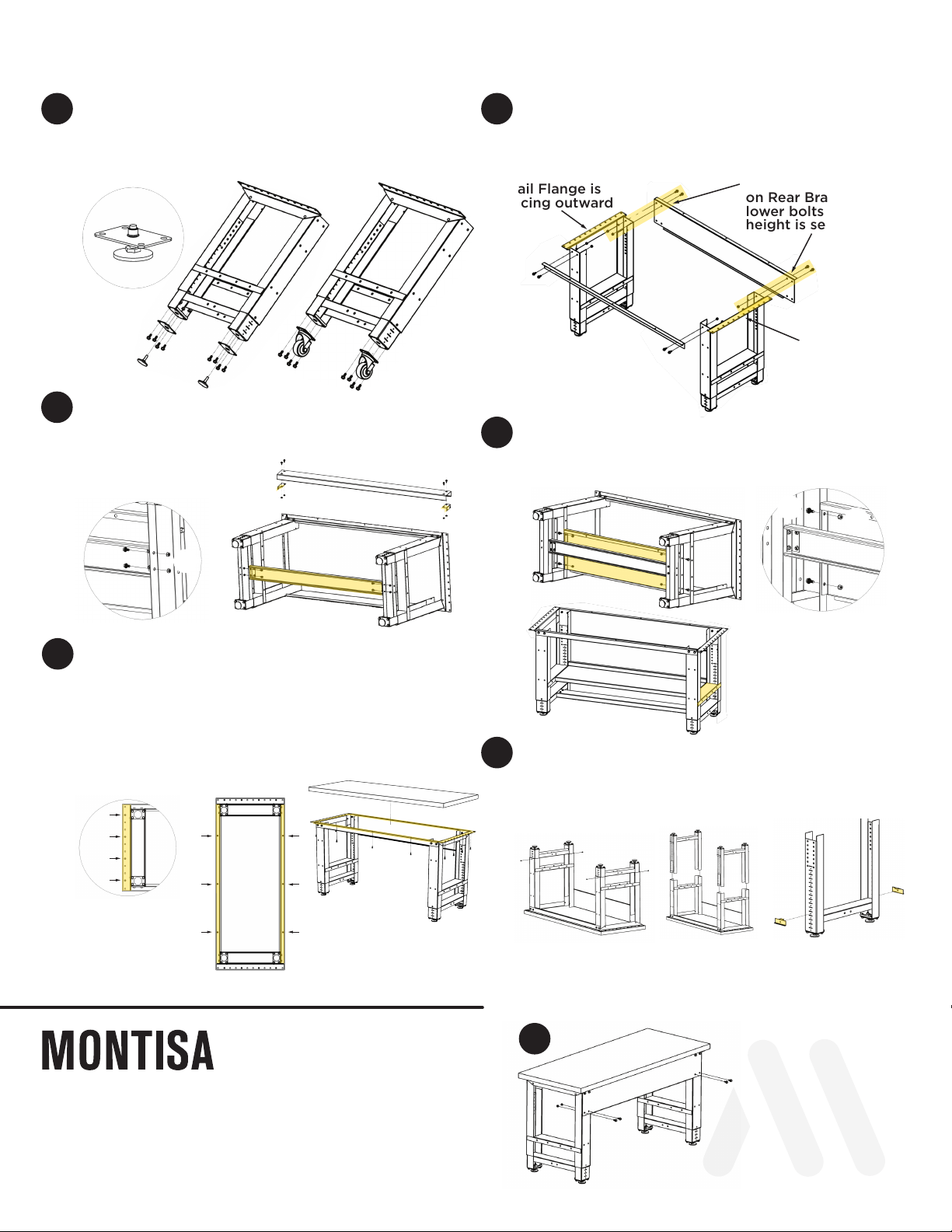
HEIGHT-ADJUSTABLE BENCH ASSEMBLY INSTRUCTIONS
1
3
5
Thread Leveler Foot (Part A) onto Leveler Plate
(Part B). Install Leveler Foot Assembly or Optional
Caster Assembly (Part G) to bench legs with (16)
5/16-18 Screws (Part C) and (16) 5/16-18 Locknuts
(Part D).
Attach Front and Rear Braces to Height-Adjust
Legs. The Flange on Top Rail needs to face out.
Only install the top (4) Screws (Part C) with (4)
Locknuts (Part D) on Rear Brace.
Attach (2) optional Footrest Brackets (Part H) to
Optional Footrest (Part I) with (4) Screws (Part M)
and Keps Nuts (Part N). Then attach Footrest
assembly to side brackets using
(4) Screws (Part M)
and Keps Nuts (Part N).
G
C
Install only top 4 bolts
on Rear Brace. (Install
lower bolts after final
height is set later.)
Make sure Top
Rail Flange is
facing outward
Note: All shelves attach
to outer weldment of
height-adjust legs.
Make sure Top
Rail Flange is
facing outward
To adjust legs to desired height, turn table over
with legs facing up. Once Height-Adjust Plate is
set at all 4 locations, re-install Height-Adjust Legs
into weldment, and re-install (4) Height-Adjust
Phillips-Head Screws.
Remove (4)
Phillips-Head
Wood Screws
Remove Height-
Adjust Legs
from Outer Leg
Weldment
Set Height-Adjust
Plates at desired
location, 24”- 42”
table heights (1”
increments)
Finish installing Rear
Brace using (4) 3/4"
Screws (Part C) with
(4) 1/2" Locknuts
(Part D).
4
6
2
7
Tops 24 wide
require (4)
Screws (Part E),
Tops over 24
wide require
(6) Screws.
Attach optional Shelves, Lower (Part J), Full-Width
Lower (Part K), and Centered Lower (Part L), with
(4) 1/4-20 Screws (Part M) and 1/4-20 Keps Nuts
(Part N).
Turn bench over and center Top Surface on bench.
On bottom of Surface, mark (4 to 6) hole
locations on each short side (based on Top size)
and (3) hole locations on each long side. Drill pilot
holes 3/4" deep using 5/32" drill bit. ***Do not
exceed 1" depth for risk of breaking through Top
Surface. Attach Top Surface with (14-18) Wood
Screws (Part E).
Attach (3) Screws
(Part E) on each side
of bottom Surface to
frame.
A
B
A
B
C
D
D
C
C
H
IM
N
M
EE
EF
F
DC
C
H
N
MN


