MONZA SP493612B User manual

Artikelnummer: OD 060366
Modelnummer: SP493612B
Artikelnummer: OD 060367
Modelnummer: SP613612B
SWIMMING POOL
INSTRUCTION MANUAL


1
WARNING!
To lessen your risk of serious injury or death, follow these rules:
IMPORTANT SAFETY INSTRUCTIONS
The following instructions contain important safety information; we strongly encourage you to read these important
safety instructions and abide by them when using the Premium Metal Wall Pool. When installing and using this
electrical equipment, basic safety precautions should always be followed, this includes the following.
WARNING!
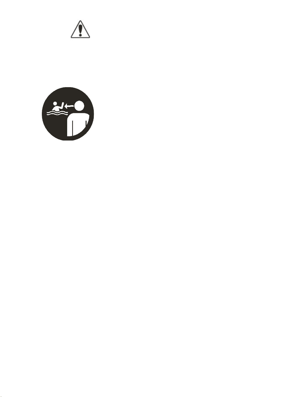
CHILDREN HAVE DROWNED IN PORTABLE
SWIMMING POOLS.
ENSURE ACTlVE ADULT
SUPERVISION AT ALL TIMES.
DO NOT LEAVE
CHILDREN UNSUPERVISED IN OR
AROUND THE POOL
-
KEEP THEM WITHIN ARMS'
REACH. POOL FENCING LAWS APPLY TO THIS POOL.
CONSULT YOUR LOCAL
GOVERNMENT A U T H O R I T Y
FOR FENCING R E Q U I R E M E N T S .
READ AND FOLLOW ALL INSTRUCTIONS.
NOTE •
Please examine equipment before use. If there are any damaged or missing parts at the time
of purchase, do
not
assemble or
operate
until parts are
replaced •
WARNING -
Consult your local council, state government or water authority in regards to the
use
of
water and
I
or water restrictions relating to this product.
WARNING -
Pool fencing laws affect this product, consult your local council and state government
Abide by state and federal law requirements such as fencing, enclosures, childproof gates, etc.
WARNING -
Water attracts children; Always remove pool ladder when not in use. Store in a place not
accessible to children.
DANGER -
Prevent the Risk of Accidental Drowning. Extreme caution must
be
exercised to prevent
unauthorized access by children. To avoid accidents, ensure that children cannot use the
Pool unless they are supervised by an adult at all times.
NEVER LEAVE CHILDREN UNATTENDED.
WARNING -
RISK OF ELECTRIC SHOCK. Connect Filter Pump only to a grounding type
receptacle protected by an RCD (Residual Current Device). Use a qualified
electrician to install the RCD, which has a maximum rate of 30mA.
WARNING -
Know where the cut-off switch for your pump Is at all times, so you can turn It
off
in an emergency. It is necessary to have the RCD (Residual Current Device)
Cut-
Off Switch plug accessible after installation of the Pool.
WARNING -
Never use an extension cord to connect the filter pump to a power source.
Doing so could cause damage to the filter pump system.

2
WARNING!
To lessen your risk of serious injury or death, follow these rules:
WARNING -
To avoid electrocution, do not permit electric devices i.e. light, telephone,
radio, television, hair dryer, etc within 2.5 Metres
of
this Pool.
WARNING -
RISK OF ELECTRIC SHOCK. Never operate any electrical appliance when in the
Pool or when your body Is
wet.
WARNING -
To reduce the risk of injury or hazard, have any damaged cord replaced immediately
by the manufacturer, its service agent, or similarly qualified persons.
WARNING -
Do not bury electric cord. Avoid using lawn mowers, hedge trimmers and other
garden equipment near or around the Metal Wall Pool and electrical cord.
WARNING -
NEVER swim or bathe in the Pool during rain or an electrical storm or If there is a
threat of lightning in the vicinity of the Pool.
WARNING - NEVER allow horseplay, diving or jumping into or around the Metal Wall Pool. Never
enter the Pool via any decks or other raised surfaces; the water level of the Pool Is
shallow. Serious injury, paralysis or death could result.
CAUTION-
It is advisable to wear protective gloves when assembling pool
NO DIVING
NO JUMPING
NO SLOPING GROUND
USE ONLY UNDER
COMPETENT SUPERVISION
SAVE THESE INSTRUCTIONS

3
Produd Contents
TOP PLATFORM
(1380mm Length)
SIDE TOP PLATFORM A
(1332mm Length}
SIDE TOP PLATFORM B
(1235mm Length}
I
TOP METAL
PIECE
UPPER JOINT
PROTECTOR
BOTTOM JOINT
PROTECTOR
SKIMMER NOTEI
For parts list please
POOL WALL
VERTICAL SUPPORT
A
A HORIZONTAL SIDE BEAM
B ANGLED SIDE BEAM
C VERTICAL SIDE BEAM
STEEL BELT
BOTTOM METAL
PIECE
M6X11 ·BOLT
M6· NUT
refer
to the
Skimmer
Box Manual
LADDER
SIDEBOTTOM
METAL PIECE A
RAIL (1375mm Leng
th)
SIDE UPPER JOINT
PROTECTOR
M6·WASHER
M6 ·SPRING WASHER
SIDEBOTTOM
METAL PIECE B
SIDE RAILA (1300mm Length) SIDE TOP METAL PIECE
SIDE RAI;LB (1175mm Length)
RAIL CONNECTOR
ST4.2X13 • SCREW
M4X10·BOLT
M8X20·BOLT
INSIDEBOTTOM
PROTECTOR
SIDE BOTTOM JOINT
PROTECTOR
M8·NUT
NOTE: Check all parts and ensure they are present and undamaged before assembly.
Report missing or damaged parts immediately
to
have them replaced.
ST6.3X19 ·SCREW

4
Selecting a Suitable Site
Carefully select the site for your new pool. This is the most important decision you will have to make to
ensure the safety and success of your pools construction. An incorrect site could cause problems in the
future that may cause injury, death or financial loss. Read carefully the check list set out below when
selecting your site.
Acceptable:
Flat, level, firm and dry ground with easy access to all
sides of the pool exposed to direct sunlight, preferably in
the morning. Safe access to electricity for running the
filter pump and other pool accessories. Access to mains
water source. Protection from wind.
Tools Required:
•
Phillips head screw driver.
•
Small Shifter
•
Clothes Pegs
•
Spirit Level
•
Sharp Knife
·Site excavation tools
•
Protective Gloves
Not acceptable:
•
Sloping ground.
•
Concrete, Asphalt, Sandy Gravel and
Swampy ground.
•
Close to wooden construction e.g.
Pergola's and decking.
•
Next to deciduous or leafy trees.
•
Over-head wires and clothes line.
•
Drains, electric wires or gas pipelines
underneath the site.
•
Poor or little drainage or high flood risk
locations.
•
High wind conditions.

5
NO.
PART NO.
PARTS DESCRIPTION
Pool
Type
SP493612B
SP613612B
1
22001001
POOL WALL
1
1
2
22001003
POOL LINER
1
1
3
22001002
LEAF SKIMMER
1
1
4
22001004
GROUND SHEET
1
1
5
22001005
POOL COVER
1
1
6
22001006
LADDER
1
1
7
22001007
HORIZONTAL SIDE BEAM
2
4
8
22001008
VERTICAL SIDE BEAM
2
4
9
22001009
ANGLED SIDE BEAM
2
4
10
22001010
STEEL BELT
1
2
11
22001011
PVC SLEEVE
1
2
12
22001012
SIDE BOTTOM METAL PIECE A
2
4
13
22001013
SIDE BOTTOM METAL PIECE B
2
4
14
22001014
INSIDE BOTTOM PROTECTOR
2
4
15
22001015
SIDE BOTTOM JOINT PROTECTOR
2
4
16
22001016
RAIL
1375mm
Leng
th
12
12
17
22001017
SIDE RAILA
1300mm Length
8
8
22001017
SIDE RAILB
1175mm Length
0
4
18
22001018
RAIL CONNECTOR
32
32
19
22001019
SELF ADHESIVE TAPE
3
3
20
22001020
TOP METAL PIECE
8
8
21
22001021
BOTTOM METAL PIECE
8
8
22
22001022
BOTTOM JOINT PROTECTOR
8
8
23
22001023
SIDE TOP METAL PIECE
2
4
24
22001024
TOP PLATFORM
1380mm
Length
6
6
25 22001025
SIDE TOP PLATFORM A
1332mm Length
4
4
22001025
SIDE
TOP
PLATFORM
B
1235mm Length
0
2
26
22001026
POOL WALL VERTICAL SUPPORT
8
8
27
22001027
UPPER JOINT PROTECTOR
8
8
28
22001028
SIDE UPPER JOINT PROTECTOR
2
4
29
22001029
M6x11-BOLT
73
89
30
22001030
M6-NUT
57
57
31
22001031
M6-WASHER
65
73
32
22001032
M&-SPRING WASHER
40
48
33
22001033
ST4.2x13-SCREW
36
40
34
22001034
M4x10-BOLT
54
60
35
22001035
M8x20-BOLT
20
40
36
22001036
MI·NUT
20
40
37
22001037
ST6.3x19-SCREW
4
8
SP493612B
4.9x3.6x1.2m(16'x 12'x 48
11
)
SP613612B
6.1x3.6x1.2m(20'x 12'x 48
11
)

6
Pool Setup
MARKING THE SITE
1.
Mark the centre of the site and drive a stake or screw driver into the soil.
2.
Tie a piece of string onto the stick. At the other end of the string, tie a funnel. The distance
between the stick and the funnel should be 15cm more than the radius of the pool
3.
Place flour, chalk dust or lime into the funnel and draw a circle around the stake. If the smallest diameter
is 360cm, then the
2
circles should be 390cm in diameter.
See diagram 1,2&3
(Diagram 2)
Side Vertical
(Diagram 1)
(Diagram 3)

7
Levelling the Area
Warning! Levelling is extremely important:
take as much time as possible to work out a site
that is completely firm and levelled.
Use a carpenter's level and straight edge to ensure that the site is completely level, flat and firm!
(See diagram 4)
The pool contains a huge amount of water and thousands of kilos of weight.
Should the pool collapse due to unlevelled ground, it could cause a lot of damage to property
and even human injury or death!
Remove the higher ground rather than filling the low laying ground
(see diagram 5)
Attention! Always remove grass and stones within the circle.
Usethe ground cover provided to ensure that the grass doesn't penetrate the pool liner and cause
damage.
(Diagram 4)
Remove high spots
Do not fill low spots
(Diagram 5)
(Diagram 6)

Pool Wall Side Frame Support Assembly
The Pool Wall Side Frame Support consists of a left and right frame connected by a stainless steel belt.
(See diagram 7)


POOL WALL SIDE FRAME SUPPORT ASSEMBLY
1.
Connect the Steel Belt to either end of the Left and Right Side Pool Frames. (See diagram 12 and 13)
Make sure the Steel Belt is protected
by
the PVC Sleeve which is provided in the package. This
will protect the Pool Liner from damage.
POOL WALL RAIL AND RAIL CONNECTOR SETUP
1.
Position the Left and Right Side Wall Frame in the middle of the prepared area
(See
diagram 14)
2.
Place the Rails around the area where the pool wall is to be installed.
(See
diagram 14)
3.
Connect the Rails together using 2 Rail Connectors per Rail
(See
diagram 15) and leave a
1.5cm gap between each connection (See diagram 16).
4.
Connect the Side Rails to the Side Bottom Metal Piece A and B either side of the Pool Wall Frame Supports
(See
diagram 17)

Produduct
Assembly
5.
Place the Bottom Metal Piece's between the joins
of the Rails with the triangular end pointing out
from the pool wall.
(Diagram 18)
(Diagram 19) INSIDE OF POOL
OUTSIDE OF
POOL
(Diagram 18)
6.
Place the Inside Bottom Protector
over the Steel Belt and screw
into the Horizontal Side Beam.
NOTE: Ensure the PVC
Sleeve covers the Steel
Belt to prevent damage or
rust effecting the pool.
(Diagram 19)
Leaf Skimmer
Cut Out
•···•···•
CAUTION: Wear protective gloves
when handling the metal wall
7. Place the Metal Pool Wall with the
Skimmer Hole at the top, onto a
piece of cardboard, ply wood or
ground cloth to protect the leveled
ground during installation.
NOTE: Position the Pool Wall's
Skimmer cutout in the same
location to where your electricity
supply will be to power the
filtration system.
(Diagram 20)
8. Rest the end of the pool wall in the Side Bottom
Metal Piece between the gap in the Side Rail. Make
sure the prepared location is not prone to constant
windy conditions. Continue unrolling and placing the
bottom edge of the pool wall into the rails until the full
length of the pool wall is sitting in the Rails
(See
Diagram 21)

10
Selecting a Suitable Site
9. On the opposite side of the
pool wall, carefully lift and
place the steel wall
in between the Side
Support Frame and the
Inside Bottom Protector.
NOTE! There is a section
cut out of the pool wall that
will allow the wall to slot
over the Horizontal
Support Beam.
(See
Diagram
22)
10. Line up the two ends of the pool wall then begin inserting and hand tightening each bolt
and nut until the full length of the join is assembled.
(See
Diagram
23) Do not
completely tighten bolts before you check the wall is in the correct place, level
and that no damage has occurred to the pool wall.
NOTE: At this stage, it is recommended that you assemble the
Pool Ladder to place over the pool wall to gain access to the
inside and outside of the Pool area's.

Measuring the Pool Wall
WARNING! A pool that is not level
is very dangerous and may collapse at anytime.
Check the pool wall level by placing a length of timber peam or similar across the diameter of the pool wall and
placing the builders level on the top pf the timber beam. (see diagram 24). If the deviation is more than 2cm (see
diagram 25) then the ground site must be level again. Check also if the pool wall is oval and measure the
diameter across a few spots to make sure the differences of each diameter measured are within 2cm.
If the levels are not to specification then the area will have to be leveled again.
CAUTION! Try not to damage any of the components when dissembling the pool wall to correct the level of the
ground.
Once the measurements and levels are correct and all nuts and bolts are tightened, then cover the exposed screw
heads with the Self Adhesive Tape
(See
Diagram 26 and 27).

10
(Diagram 26)
(Diagram 27)
Place the Self Adhesive Tape over the
exposed screw heads to seal them off.


12
MAKING A PROTECTIVE SAND CUSHION AT THE FOOT OF THE INNER POOL WALL
Pool Liner
Seam is
centred in the
middle of the
sand cove
Pool Wall
To protect the liner against the rail and the pool wall, it is recommended to create a protective covering made of
fine brick sand at the foot of the pool wall.
(See
diagram 28, 29).
The size should be 15cm H x 15cm W so that it
completely seals the rail but doesn't distort the pool liner.
FITTING THE PVC POOL LINER
Fit the PVC liner on a warm and sunny day, preferably above 22·c. Unfold the PVC liner and put it in the sun
for 2 hours. This helps to soften the PVC. If the temperature is below 1s·c, the PVC liner will be hard and rigid
and quite difficult to handle. Put the liner at the centre of the pool site inside the pool wall. Extend it evenly until
the seam line reaches the base of the pool where the protective sand cover is. Smooth out all the wrinkles in
the liner. Straighten the PVC liner and hold it perpendicular to the ground. Drape the pool liner over the pool
wall. There should be an overlap of Scm of the pool wall height
(See
diagram 30 and 31)
Hold the overlap in
place with clothes pegs.
(Diagram 30) (Diagram 31)
Check if the pool liner is placed evenly around the perimeter. Evenly fold the excessive length of the PVC if you
find it a bit loose. Check if the overlap is uniform. If the pool liner is slightly short, then you will have to let it down
and vice versa. Fill the pool with 3 to Scm height of water to smooth out the liner against the pool wall. Check to
see if water is level, if not, something is wrong and you will have to dismantle the liner and pool wall to access and
level the ground area.

Remove one peg at a time whilst applying the top rails (See
diagram
32}. Slide the pipe connectors into one end of
the top rail, then connect another top rail, continue around the circumference until all top rails are joined together
and firmly pressed into the top of the pool wall.
CAUTION! Do not cut the excess overlap of
the pool liner wall. If you cut the overlap, it
will make the next pool installation difficult.
Fix all top rails to the top of the pool wall and
make sure they are all sitting properly.

14
INSTALLING THE TOP AND SIDE METAL PIECES
Hook the top metal pieces over the top rail between the rail connections and align with the Bottom Metal Pieces.
{See
Diagram 33)
Place the Side Metal Pieces over the top of the Vertical Side Beams and Rails and screw into place.
{See Diagram 34)
This manual suits for next models
3
Table of contents
Other MONZA Swimming Pool manuals
Popular Swimming Pool manuals by other brands

Sunn Fun
Sunn Fun ROUND POOL Assembly instructions

grabner
grabner HAPPY CAT LIGHT owner's manual

Mighty sun
Mighty sun BRACELESS OVAL POOLS Universal instructions

Procopi
Procopi Proswell Tropic OCTO installation instructions

Intex
Intex Ultra Rondo 128910GH owner's manual

Piscine Laghetto
Piscine Laghetto BABY instructions