Cornelius NH User manual

V0_2020-06-25
When selecting the site for your pool, take into account city by-laws regarding fences and utilities laws pertaining to electrical cables
as well as the landscaping which you are planning once the pool is installed.
Dear Customer
Congratulations! You have purchased a pool of superior quality and durability. To achieve the best possible results,
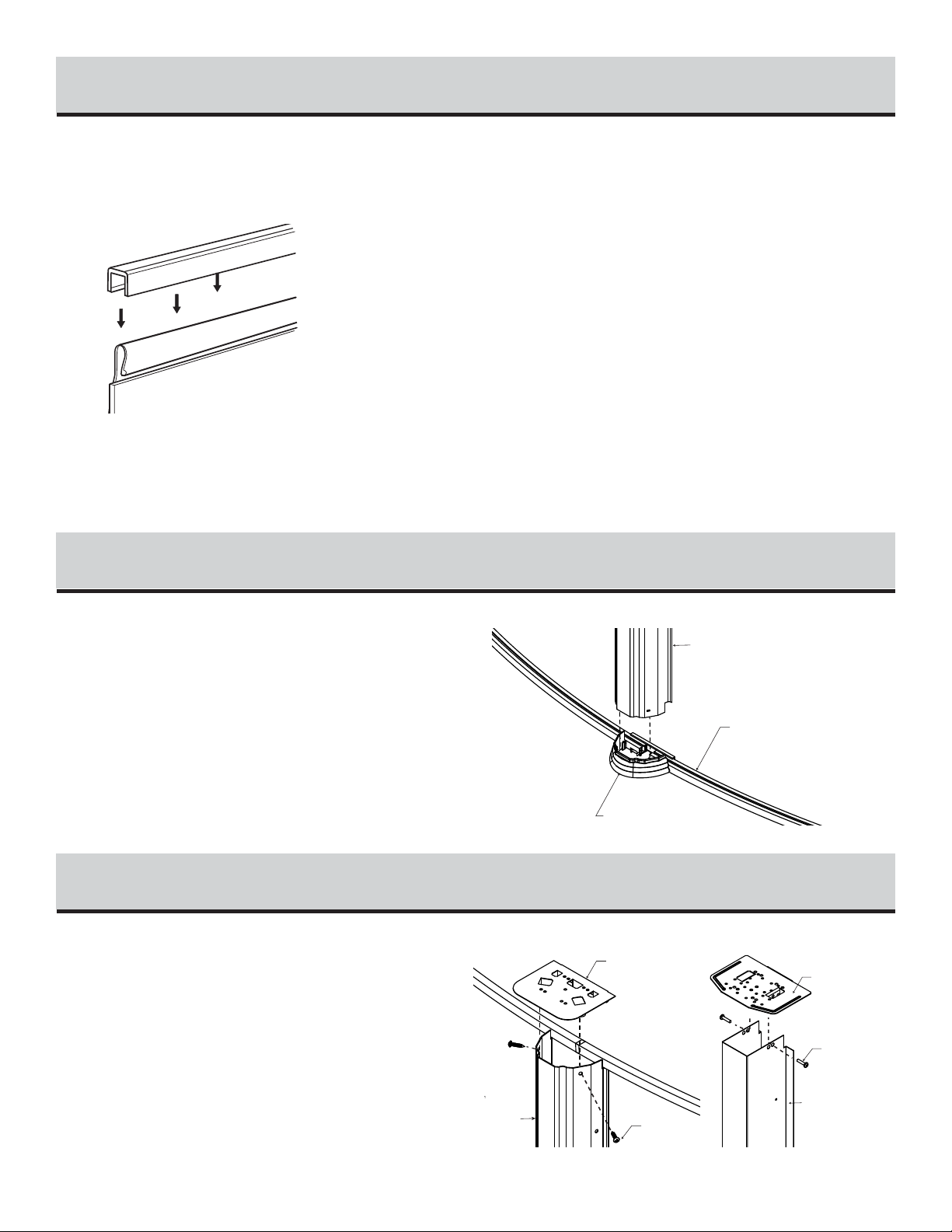
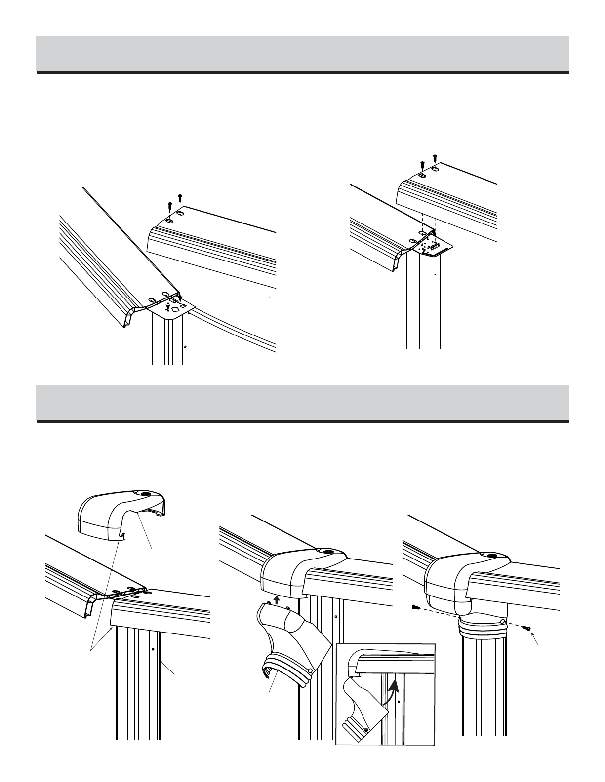
follow the instructions carefully. Failure to follow the installation procedures may result in damage to your pool or
property and void your warranty. We recommend that you make a preliminary study of the instruction booklet to
familiarize yourself with the different parts of your pool. Make sure that you understand each step thoroughly before
you begin assembling.
We wish you a most pleasant and refreshing summer.
WARNING: Be sure you have read and understand the “Safety Information” sheets
before you begin your pool installation.
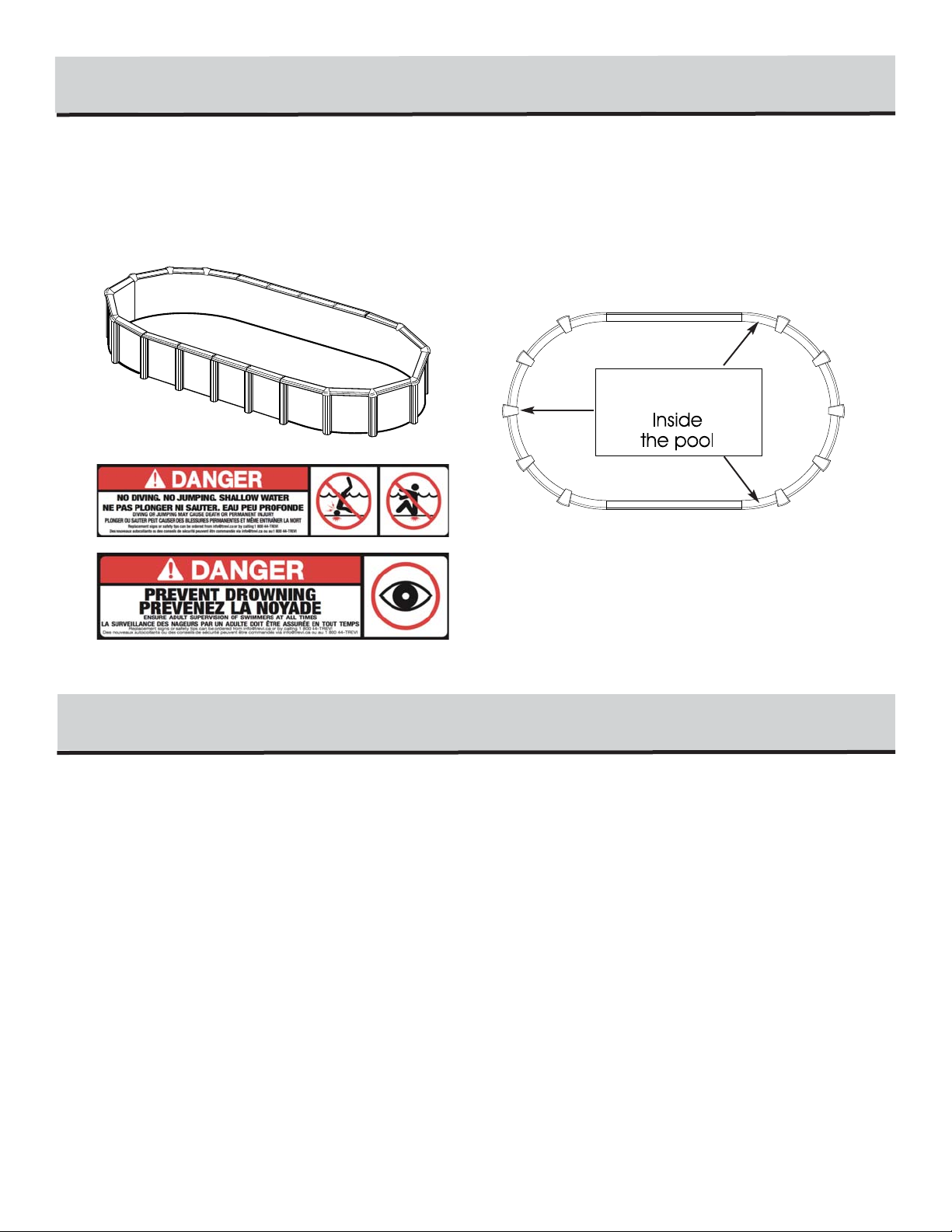
WARNING: For your safety, your pool is not designed for diving and/or jumping head first.
Please do not dive. Diving may result in permanent injury or death.
ASSEMBLY INSTRUCTIONS
OVAL POOLS
MODEL NH
SITE PREPARATION
1
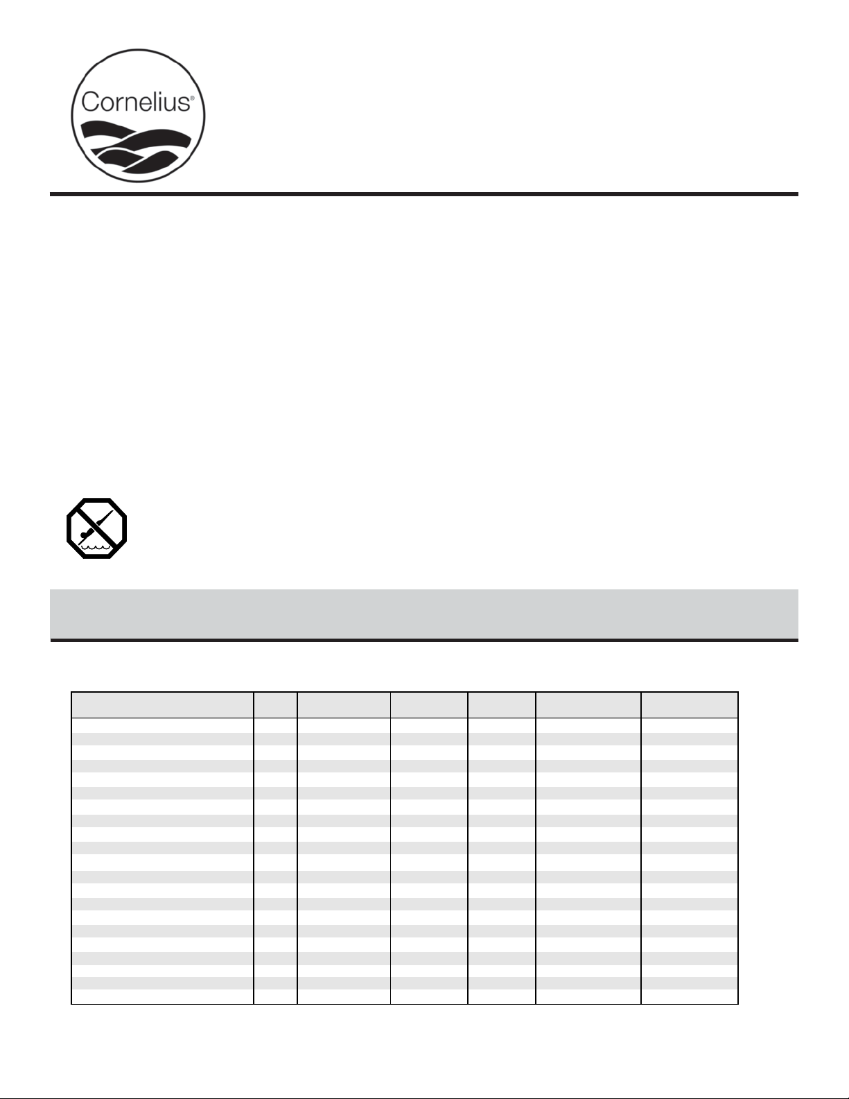
Chart 1.1 - Grass removal area (Figure 1.1)
1.70m (5'7")
1.70m (5'7")
2.13m (7')
2.13m (7')
2.44m (8')
2.44m (8')
2.44m (8')
2.90m (9'-6")
2.90m (9'-6")
2.90m (9'-6")
3.35m (11')
3.35m (11')
4.27m (14')
4.27m (14')
4.88m (16')
4.88m (16')
4.88m (16')
5.79m (19')
5.79m (19')
5.79m (19')
5.03m (16'-5 3/4")
6.69m (21-11")
5.48m (17'-11 3/4")
7.14m (23'-5")
6.30m (20'-8")
7.96m (26'-1 1/2")
9.64m (31'-7 1/4")
10.31m (33'-10")
11.98m (39'-4")
13.66m (44'-10")
1.90m (6'-3 1/2")
3.33m (10'-11")
1.66m (5'-5 1/2")
3.33m (10'-11")
1.66m (5'-5 1/2")
3.33m (10'-11")
4.99m (16'-4 1/2")
5.24m (16'-4 1/2")
6.90m (22'-8")
8.56m (28'-1 1/2")
MODELTRUE POOL SIZE
DISTANCE (A-B)
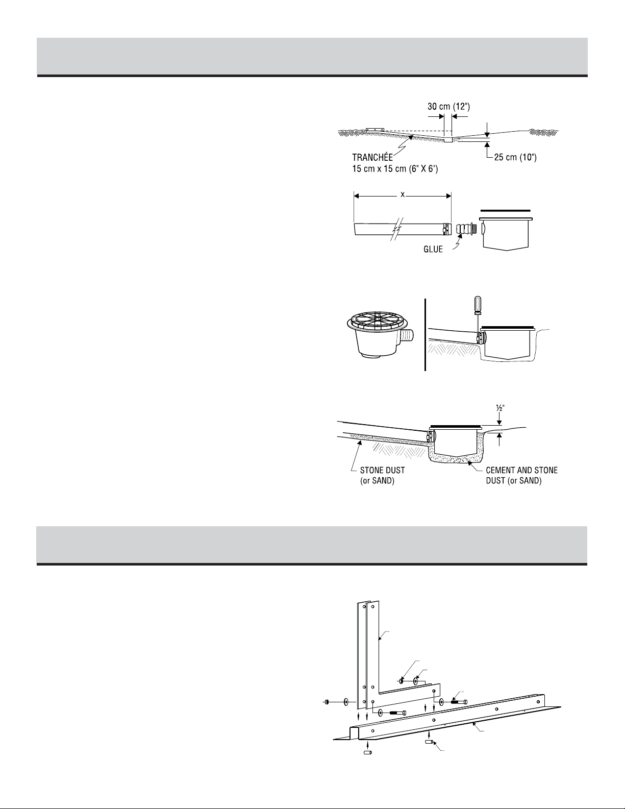
RADIUS (R) WIDTH (D) TOTAL LENGTH (E) TRENCH (F)
10'x16' 1.68m (5'-6")
10'x21' 3.35m (11'-0")
13'x17' 1.18m (3'-10 1/2")
13'x23' 2.84m (9'-3 3/4")
15'x20' 1.42m (4'-7 3/4")
15'x26' 3.07m (10'-1")
15'x31' 4.75m (15'-7")
18'x33' 4.57m (15'-0")
18'x38' 6.25m (20'-6")
18'x44' 7.92m (26'-0")
3.05 x 4.72 m (10' x 15' 5-3/4")
3.05 x 6.38 m (10' x 20' 11-1/8")
3.96 x 5.17 m (13' x 16' 11-3/4")
3.96 x 6.83 m (13' x 22' 5")
4.57 x 5.99 m (15' x 19' 8")
4.57 x 7.65 m (15' x 25' 1-3/8")
4.57 x 9.33 m (15' x 30' 7-1/4")
5.44 x 10.00 m (17' 10" x 32' 10")
5.44 x 11.61 m (17' 10" x 38' 4")
5.44 x 13.36 m (17' 10" x 43' 10")
1.40m (4'7 1/2")
1.40m (4'7 1/2")
1.40m (4'7 1/2")
2.75m (9')
2.75m (9')
2.75m (9')
4.45m (14'-7")
5.03m (16'-6")
6.12m (20'-1")
1.90m (6'-3 1/2")
3.33m (10'-11")
3.58m (11'-9")
8'x14' 1.68m (5'-6")
8'x16' 2.45m (7'-5")
8'x19' 3.35m (11'-0")
2.46 x 4.14 m (8' 1"x 13' 7")
2.46 x 4.72 m (8' 1"x 15' 6")
2.46 x 5.82 m (8' 1"x 19' 1")
1.70m (5'7") 3.35m (11') 5.85m (19-2 1/2") 3.33m (10'-11")
10'x18' 2.45m (8'-3")3.05 x 5.53 m (10' x 18' 2-1/2")
1.98m (6'6 3/4")
1.98m (6'6 3/4")
1.98m (6'6 3/4")
3.96m (13')
3.96m (13')
3.96m (13')
5.94m (19'-6")
7.59m (24'-11 1/2")
8.43m (27'-8 1/4")
1.90m (6'-3 1/2")
3.58m (11'-9")
5.23m (17'-2 1/2")
12'x18' 1.98m (6'-6 1/2")
12'x24' 3.65m (12'-0")
12'x27' 4.47m (14'-8")
3.65 x 5.63 m (11' 11-1/2"x 18' 6")
3.65 x 7.30 m (11' 11-1/2"x 23' 11-1/2")
3.65 x 8.12 m (11' 11-1/2"x 26' 8-1/4")
2.31m (7'7 1/2")
2.31m (7'7 1/2")
4.57m (15')
4.57m (15')
6.27m (20'-7")
7.95m (26'-1")
1.90m (6'-3 1/2")
3.58m (11'-9")
14'x20' 1.68m (5'-6")
14'x25' 3.35m (11'-0")
4.29 x 5.97 m (14' 1"x 19' 7")
4.29 x 7.65 m (14' 1"x 25' 1")
2.59m (8'6 1/2")
2.59m (8'6 1/2")
5.18m (17')
5.18m (17')
8.38m (27'-6")
10.05m (33')
3.58m (11'-9")
5.23m (17'-2 1/2")
16'x26' 3.23m (10'-7 1/2")
16'x32' 4.90m (16'-1")
4.85 x 8.08 m (15' 11"x 26' 6")
4.85 x 9.75 m (15' 11"x 32' )

1) Drive a stake into the ground at points A and B respecting the
distance of the straight section between those two points (A-B).
2) Draw two half circles respecting the radius (R).
3) Join the two half circles with straight lines respecting the width
between these two lines (D).
4) Verify that the total length is consistent. (E)
5) Add 15cm (6”) wide trenches on each side, respecting the length
(F)
6) Remove all grass from the area you have just outlined.
SITE PREPARATION (continued)
1
SITE LEVELLING
2
AB
A-B
R
R
D
15cm(6”)
E
F
POOL WALL
AREA TO OUTLINE
Figure 1.1
SITE LEVELLING
For an oval pool, the bottom must absolutely be levelled, using a
carpenter's level and a straight plank. Eliminate any protrusions.
Ensure that the surface is free of debris such as rocks, wood, etc.
TRENCHES FOR BUTTRESS ASSEMBLIES
1) Dig trenches to a depth equal to the thickness of the patio blocks
(2” thick slabs recommended) and the thickness of the buttress
assembly beam 8cm (3 1/4”).
(Refer to illustrations for trench layout details).
2) Make sure trenches are smooth and leveled without compacting
them.
3) Place and level patio blocks into trenches. Make sure that the
top of the slab is 8cm (3 1/4”) deep. Top of framework must be
level with pool area.
Chart: Sand quantity
8x14, 8x16, 8x19,
10x16, 10x 18 12x18, 12x24, 12x27, 13x17,
13x23,14x20, 14x25, 15x20 15x26, 15x31, 16x26,
16x32, 18x33 18x38, 18x44
141" - 358cm
22-3/4" 22-3/4"
10" 10" 10"
25cm 25cm 25cm 25cm 25cm
141" - 358cm
22-3/4" 22-3/4"
10" 10" 10"
25cm 25cm 25cm 25cm 25cm
FOR:
8x19: 12" (30cm)
10x21: 36" (91cm)
12x24: 60" (152cm)
13x23: 72" (183cm)
14x25: 84" (213cm)
15x26: 96" (244cm)
16x26: 108" (274cm)
22-3/4" 22-3/4"
58cm 58cm 58cm
10" 10"
3-1/4" - 8cm
DEEP
15cm
31"
79cm
22-3/4" 22-3/4"
58cm 58cm 58cm
10" 10"
3-1/4" - 8cm
15cm
6"
31"
79cm
122cm
6"
15cm
6"
58cm
48"
6"
15cm
43cm
58cm
48"
17"
6"
15cm
R
A-B
R
10"
10"
10" 22-3/4"
22-3/4"
75-1/2" - 192cm
3-1/4" - 8cm
DEEP
15cm
25cm
25cm
25cm
6"
15cm
31"
79cm
FOR:
8x14: 12" (30c
m
8x16: 12" (30c
m
10x16: 36" (91c
m
10x18: 36" (91c
m
12x18: 60" (152
c
13x18: 72" (183
c
14x20: 84" (213
c
15x20: 96" (244
c
10"
10"
10" 22-3/4"
22-3/4"
75-1/2" - 192cm
3-1/4" - 8cm
15cm
25cm
25cm
25cm
6"
15cm
6"
43cm
31"
79cm
58cm
58cm
17"
48"
122cm 6"
15cm
R
A-B
R
15cm
3-1/4" - 8cm
DEEP
6"
79cm
15cm
FOR:
12x27: 60" (152cm)
15x31: 96" (244cm)
16x32: 108" (274cm)
18x33: 132" (335cm)
3-1/4" - 8cm
122cm
6"
79cm
31"
17"
31"
48"
6"
15cm
43cm
206-1/2" - 525cm
22-3/4" 22-3/4" 22-3/4"
58cm
22-3/4"
58cm
10" 10" 10" 10" 10"
25cm 25cm 25cm 25cm 25cm
25cm
206-1/2" - 525cm
22-3/4"
58cm
22-3/4" 22-3/4" 22-3/4"
58cm
22-3/4"
58cm
10" 10" 10" 10" 10"
25cm 25cm 25cm 25cm 25cm
25cm
10"
10" 22-3/4"
22-3/4"
58cm
58cm 58cm
25cm 10"
10" 58cm
22-3/4" 58cm 58cm
25cm
58cm
6"
15cm
R
A-B
R
15cm
3-1/4" - 8cm
DEEP
6"
79cm
15cm
FOR:
18x38: 132" (335cm)
3-1/4" - 8cm
122cm
6"
79cm
31"
17"
31"
48"
6"
15cm
43cm
272" - 691cm
22-3/4" 22-3/4" 22-3/4"
58cm
22-3/4"
58cm
10" 10" 10" 10" 10"
25cm 25cm 25cm 25cm 25cm
25cm
22-3/4"
58cm
22-3/4" 22-3/4"
10" 10" 10"
25cm 25cm 25cm 22-3/4"
58cm
10"
25cm
22-3/4"
58cm
10"
25cm
25cm
10"
10" 22-3/4"
22-3/4"
58cm
58cm 58cm
25cm 10"
10" 58cm
22-3/4" 58cm 58cm
25cm
58cm
6"
15cm
R
A-B
R
15cm
3-1/4" - 8cm
DEEP
122cm
6"
79cm
15cm
FOR:
18x44: 132" (335cm)
3-1/4" - 8cm
6"
79cm
17"
31"31"
48"
6"
15cm
43cm
337-1/2" - 857cm
22-3/4" 22-3/4" 22-3/4"
58cm
22-3/4"
58cm
10" 10" 10" 10" 10"
25cm 25cm 25cm 25cm 25cm
25cm
22-3/4"
58cm
22-3/4" 22-3/4"
10" 10" 10"
25cm 25cm 25cm 22-3/4"
58cm
10"
25cm
22-3/4"
58cm
10"
25cm
22-3/4"
58cm
10"
25cm
22-3/4"
58cm
10"
25cm
25cm
10"
10" 22-3/4"
22-3/4"
58cm
58cm 58cm
25cm 10"
10" 58cm
22-3/4" 58cm 58cm
25cm
58cm
6"
15cm
R
A-B
R

Dig a hole 30 cm (12") wide by approximately 25 cm (10") deep in
the center of the circumference.
From the center hole to the projected location of the pool motor, dig
a 15 cm (6") wide trench. Place the removed soil aside to be used
later to cover the hose.
Bottom Drain Assembly
Place teflon tape around the threaded plug. Screw in drain holes
using large pliers. Glue the connector in the appropriate opening.
Take one of the two rubber rings and adjust it to the top of the drain,
aligning the holes carefully. Secure with strips of adhesive tape to
prevent sand from penetrating inside the holes once the drain has
been installed.
Secure one end of the long black or white hose inside the drain
spout. First apply glue on the drain spout and inside the drain end,
then secure with one or two collars.
Cut the hose so that it ends with the stone dust (or sand). Measure
the pool radius from the center of the drain, then add 15 cm (6").
Place the assembled bottom drain in the hole so that it is approxi-
mately 1.3cm (1/2") higher than the surface soil. Bury the hose,
levelling the drain as much as possible. Compact the soil, using
your feet and a tampering tool as well.
Mix three (3) shovels of stone or sand dust with one half shovel of
pure cement, adding a small quantity of water, then pour the cement
around the drain until it reaches 1.3 cm (1/2") from the top.
BOTTOM DRAIN ASSEMBLY (if applicable)
3
1) Refer to Illustration 4.1. To assemble, join splice brackets (R)
to the foot beam (Q) using the bolt 1/2 "X 3" X #13 (12.7 mm x
76.2 mm) (U), nuts (UU ) and washers (V). Remember to insert a
spacer (T) inside the foot beams aligned to each bolt.
STRAIGHT SECTION BUTTRESS ASSEMBLY
4
SPLICE BRACKET
WASHER 1/2”
NUT 1/2”
FOOT BEAM
SPOOL SLEEVE
BOLT 1/2” X 3”
Illustration 4.1

2) Refer to Illustration 4.2. Assemble the buttress post using
bolts 1/2" X 3" X #13 (12,7 mm X 76,2 mm) (U), nuts (UU) and
washers (V). Remember to insert a spacer (T) and two washers
(V) inside the butress post aligned to each bolt.
3) Refer to Illustration 4.3. Cover the bolt heads with bolt cap
covers (W) and insert the styrofoam block (X) at both ends of foot
beam.
STRAIGHT SECTION BUTTRESS ASSEMBLY (continued)
4
1/2” BOLT CAP COVER
STYROFOAM CAP
FOOT BEAM
BUTTRESS POST
SPACER
BOLT 1/2” X 3”
NUT 1/2”
ER 1/2”
Illustration 4.3
Illustration 4.2
1) Position the buttress posts assembled in Step 4 on the patio
blocks in the trenches previously dug.
2) Refer to Illustration 5.1 : Once the buttress posts are placed
in the trenches, assemble the straight section bottom tracks (J) be-
tween the buttress posts on the foot beams.
3) Refer to Illustration 5.2 : Fix the pressure plates between the
foot beams with four (4) standard screw ‘’Z’’.
BOTTOM TRACKS (straight section) AND PRESSURE PLATES
5
BOTTOMTRACK
STRAIGHT SECTION
STANDARD
SCREW #14
PRESSURE PLATE
Illustration 5.2
Illustration 5.1

1) Study illustrations and chart carefully. You are now ready to as-
semble the metallic tension straps. Refer to indications on the chart
for the exact number of tension straps per row according to their
respective pool size.
2) Refer to Illustration 6.1: If there is more than one metallic
strap per row, assemble the straps together using 4 bolts and nuts
(BB) 1/4" #20 X 5/8" (6,35 mm X 15,88 mm), taking care of plac-
ing the bolt head on top.
3) Attach the assembled tension straps to the foot beams on both
sides, using four (4) standard screws ‘’Z’’.
TENSION STRAPS ASSEMLBY
6
Start with round section, refer to illustration 7.1 :
Place the end of the first round section bottom track on the foot
beam of the last buttress post of the straight section. Place the first
bottom plate of the round section, at the other end of the bottom
track.
Round section, refer to Illustration 7.2 :
Using the round section bottom tracks and the bottom plates, start
with the first plate of the round section. Repeat this procedure until
the half circle is completed.
Refer to Illustration 7.3. :
Before going to the next step, make sure that the centre of the pool
is properly squared and the metallic tension straps are straight with
no buckles.
ROUND SECTION BOTTOM TRACKS ASSEMBLY
7
Chart
BUTTRESS ASSEMBLY
BOLT 1/4” X 5/8”
NUT 1/4”x 5/8’’
TENSION
STRAPS
Illustration 6.1
1ST BOTTOM TRACK
ROUND SECTION
1ST BOTTOM PLATE
ROUND SECTION
BOTTOM TRACK
STRAIGHT SECTION
Illustration 7.3
Illustration 7.1
BOTTOM
PLATE
Illustration 7.2
8x14
3
3
1
8x16
4
3
1
8x19
5
5
1
10x16
3
3
1
10x18
4
3
1
10x21
5
5
1
12x18
6
3
2
12x24
10
5
2
12x29
12
7
2
13x17
6
3
2
13x23
10
5
2
14x20
6
3
2
14x25
10
5
2
15x20
6
2
2
15x26
15
5
3
15x31
21
7
3
16x26
15
5
3
16x32
21
7
3
18x33
21
7
3
18x38
27
9
3
18x44
33
11
3
POOL SIZES
TENSION STRAPSQUANTITY (TOTAL)
ROWSTOASSEMBLE
STRAPSPERROW
Do not use impact gun to screw the tension straps.
Minimumtorque force of 60 inch
pounds to maximumof 85 inch pounds.

WALL INSTALLATION
8
1) Add sand.
2) Choose the filter location beside a round section (never in a
straight section). The starting point should be at that location where
the skimmer and return holes are, and as close as possible to the
filtration system.
3) Before uncoiling the wall, make sure the pre-punched holes for
the skimmer and pump return are at the top and facing the planned
location of your filter.
D
SAND
PLANKS
PEGS AND
STRINGS
BOTTOM PLATE
BOTTOM TRACK
PUMP RETURN
HOLE
WALL
SKIMMER HOLE
End
Begin inserting the wall into the bottom tracks in the middle of a
bottom plate. At first, the wall is kept in place with one or two pegs
and strings (or extra persons). One person uncoils the wall on a
beam or a plank, while a second person inserts it in the bottom
tracks. Do not uncoil more than 3 m (10') of wall before you install
a support bar or peg and string to reinforce the structure.
Once the wall is completely uncoiled, you may find that it is too
long or that both ends do not meet by a few centimetres. If such is
the case, adjust tracks and bottom plates until wall holes line up. If
this does not work, roll up the wall again, realign the grooves and
uncoil the wall again. If the spread is too wide, measure the wall
and check it against the chart below.
Join both ends of the wall by orienting folds outward to hide the ex-
clamation icon. (Illustration 8.1)
Note: If the wall is attached properly, you should no longer see
the exclamation icon. If you can always see the icon, you must
reverse the overlap.
Insert bolts and nuts in every hole and tighten with wrench (screw
head on water side of wall). Tape over screw heads with duck tape.
8x14
36' 4 3/4"
(11,09m)
8x16 8x19 10x16 10x18 10x21 12x18 12x2412x27 13x17
CHART OF ACTUAL LENGTHSOF STEEL WALL ACCORDING TOMODEL
41' 10 1/2"
(12,75m)
47' 4 3/4"
(14,42m)
42' 5"
(12,92m)
53' 5"
(16,25m)
47' 10"
(14,58m)
50' 7"
(15,42m)
61' 7"
(18,77m)
66' 12"
(22,00m)
48' 11"
(19,91m)
13x23 14x20 14x25 15x20 15x26 15x31 16x26 16x32 18x33 18x38 18x44
59' 10"
(18,24m)
55' 3"
(16,84m)
66' 3"
(20,19m)
56' 6" 67' 5" 78' 5"
(17,22m) (20,55m) (23,90m)
71' 2"
(20,69m)
82' 2"
(25,06m)
86' 97'
53' 10-3/16" (x2)
(26,21m) (29,56m) (16,45m x2)
Do not use impact gun for wall
screws.
Minimumtorque force of 60 inch
pounds to maximumof 85 inch pounds.
Outside of pool
Inside of pool
Fold
Fold
BOLT End
Start
NUT
Inside of pool
Outside of pool
!
IMPORTANT! Installing the wall joint in non-compliance with the specifications dictated by the manufacturer will void the warranty.
A
faulty installation will cause the wall/joint to split which could result in serious and/or fatal injuries!
Illustration 8.1

You can now spread approximately 10 cm (4") of compacting sand
all around the inside base of the wall in order to protect the liner
from the cutting edges of the bottom tracks and the stone dust (if
applicable), or install a prefabricated cove if available.
SAND BASE FINISHING
Level finishing sand one last time. Make sure that any sharp stones,
debris or roots have been removed from the surface. For better pro-
tection, spray sand with water and pack it once more until the base
is nicely even.
SAND BASE FINISHING
9
Before pulling the liner up against the wall, insert a vacuum cleaner
hose down into the pump return hole to approximately 15 cm (6")
from the ground.
Maintain the hose in place with adhesive tape. Don't forget to block
the skimmer hole with adhesive tape to prevent air from leaking in.
Place the unfolded liner in the center of the pool area at right angles
with the skimmer hole. Make sure you wear light, flat-soled shoes
to walk on the sand as the slightest heel mark could be visible once
the pool is filled.
Carefully unfold the liner, bringing the bottom-sidewall seam close
to the wall base. Make sure that the side with the protruding seams
faces downward or that the patterned side faces upward.
Lift up a section of the liner over the top of the wall leaving a 10 cm
to 15 cm (4" to 6") fringe outside the wall. Secure the liner with a
plastic coupler (sold separately). Install the top track on the wall
then install the top plates on top of each upright.
At this point, the liner may be too tight, making it difficult to drape
the overlap or, on the contrary, too loose. In such cases, you will
have to redistribute the tension in the liner by removing some of the
couplers and readjusting the liner.
VINYL LINER INSTALLATION
10
LINER
WALL
30 cm (12")
10 cm (4")
SAND COVE
(or PREFAB COVE) BOTTOM
TRACK
PUMP RETURN HOLE
VACUUM CLEANER
INNER WALL
GROUND LEVEL
15 cm (6")
OVERLAP
LINER
RESIN
TOP TRACK
WALL
PLASTIC
COUPLER
(SOLDSEPARATELY)

VINYL LINER INSTALLATION (continued)
10
Installation detail of a bead liner with top track.
Hang the liner on the top of the wall and install the top track to se-
cure.
Start the vacuum cleaner to allow the liner to adhere to the wall and
check for excess tension at the bottom or for wrinkles. Adjust the
liner by removing wrinkles if needed, lift or lower it in order to ensure
a perfect fit.
Fill the pool with water up to the base of the wall before stopping
and removing the vacuum cleaner.
PUMP RETURN FITTING
After you remove the vacuum cleaner, you may install the return fit-
ting. Place the return fitting ring against the liner and adjust it so
that it is perfectly aligned with the hole in the wall. When the ring is
properly positioned and secured, cut the liner in the middle of the
ring.
Insert the return fitting from the inside, placing the first gasket be-
tween the return fitting and the liner and the second between the
wall and the liner. Then tighten the outside ring with large pliers, tak-
ing care not to crease the liner.
BOTTOM DRAIN (optional)
Find the holes through the middle of the liner and screw the ring
and gasket in against the liner before cutting the liner in the middle
of the ring, then screw on the drain cover.
UPRIGHT POST INSTALLATION
11
For the round section:
Clip the uprights to the bottom plates.
Make sure the upright is well snaped into the bottom plate.
Uprights must be installed inside the bottom plate.
BOTTOM PLATE
BOTTOM TRACK
UPRIGHT
U-BEAD
LINER
RESIN
TOP TRACK
WALL
UPRIGHT POST TOP PLATE
12
Install the top plate into the upright, in the round and straight section,
and secure with two (2) screws ‘’Z’’ on each side.
SCREW ‘’Z’’
UPRIGHT
TOP PLATE
TOP PLATE
SCREW ‘’Z’’
BUTTRESS POST

TOP SEAT INSTALLATION
13
Place the top seats on the top of the uprights. Center the top seat
between the two the uprights and be certain to evenly distribute the
ledges all around.
Be sure to have a vertical (plumb) upright before fixing the top seat.
Secure the top seat in place using four (4) screws "Z" .
Same installation procedure for the straight section.
SEAT CAP INSTALLATION
14
Snap the seat cap starting outside the top seat.
Then snap the other side inside the top seat.
Snap the two front hooks of the seat cap extension in the two holes
under the seat cap.
Secure the seat cap extension in place using two (2) screws ‘’Z’’.
Same installation procedure for the straight section.
EXTENSION
SEAT CAP
SEAT CAP
UPRIGHT
FIX THE FRONT
HOOK FIRST
SCREW ‘’Z’’

SECURITY LABELS INSTALLATION
15
FILTRATION SYSTEM ASSEMBLY
16
Assemble skimmer, inlet, drain, filter, pumps, hoses according to separate
manufacturer’s instructions.
Note: See 'Safety Information" Manual.
Install the four (4) safety labels (DANGER) supplied with your pool
as follows: two (2) labels visible at the entrance to the pool and two
(2) visible at the main access of the backyard.
Install a minimum of three (3) safety labels (supplied with the liner)
inside the pool so that at least one label is visible no matter where
the bather enters the water (see drawing for positionning)
Important: if you require additional labels, please contact us at
Corneliuspools.com
LABEL

PARTS LIST
17
ITEMDESCRIPTION
POOL WALL (finished lenght, inch)
BOLT & NUT FOR 52" (OR 54")WALL
POOL LINER
PLASTICCOUPLER(SOLDSEPARATELY)
TOP SEAT - ROUNDSECTIONS
TOP SEAT- STRAIGHT SECTIONS
BOTTOM PLATE
UPRIGHT 52'' or UPRIGHT 54''
TOP PLATE - ROUNDSECTION
SEAT CAP
TOP TRACK - ROUNDSECTIONS
TOP TRACK - STRAIGHT SECTIONS
BUTTRESS ASSEMBLY
BUTTRESS POST
SEAT CAPEXTENSION STRAIGHT SECTION
FOOT BEAM
SPLICE BRACKET
PRESSURE PLATE
SPOOL SLEEVE
BOLT 1/2" X 3" X #13 (12,7 mm X 76,2 mm)
NUT 1/2" (12,7 mm)
WASHER1/2" (12,7 mm)
BOLT CAPCOVER
FOOT BEAM STYROFOAM BLOCK
TENSION STRAP
1/4" #20 X 5/8" (6,35 mm X 15,88 mm) SCREW & FLANGE NUT
STANDARD SCREW (SCREW #14 ,1" LENGTH)
AA
BB
DD
CC
A
B
C
D
E
F
G
J
K
L
O
P
Q
R
S
T
U
UU
V
W
X
Y
BB
Z
SEAT CAPEXTENSION
H
TOP PLATE - STRAIGHT SECTIONS
I
BOTTOM TRACK - ROUNDSECTION
BOTTOM TRACK -
STRAIGHT SECTIONS
* SEE DRAWING PARTS NEXT PAGE
NOTE: Please confirm quantities with checklist included in each box.

PARTS LIST
17
BB Z
T
U
UU V
DD
AA
K
BB
CC
A
Z
C
G
E
D
F
H
U
W
T
X
O
Z
J
Q
V
B
L
S
T
R
F
UU
PY
X
BB
Z
I
Z
Z
Z
ROUND SECTIONSTRAIGHT SECTION

SAFETY AND FUN GO
TOGETHER!
SAFETY INFORMATION
Read this before installing your above-ground pool.
12 775, Brault Street, Mirabel, Quebec, Canada J7J 0C4
Phone: 1 800 44-TREVI (1 800 448-7384)
Fax: 1 866 777-0167

The pool is subject to wear and deterioration if not maintained prop-
erly. Certain types of excessive or accelerated deterioration can lead
to failure of the pool’s structure, which may release large quantities
of water that could cause bodily harm, death and property damages.
In order to ensure proper water drainage around the pool, a 2-degree
slope needs to be erected around the perimeter of the pool. THE
MANUFACTURER WILL NOT BE HELD RESPONSIBLE FOR ANY LI-
ABILITY SHOULD THIS STEP BE OMITTED.
Before installing your pool, you should check local regulations such
as building codes, zoning requirements and electrical codes to de-
termine whether a building permit or electricity permit is required to
install your pool. Local regulations may ask you to make sure your
backyard meets set-back requirements, install gates, barriers or
other safety devices, or meet other conditions.
WARNING: All pool components, such as the filtration system,
pump and heater and other objects, should be positioned so that
people cannot use them to gain access to the pool or the deck.
Positioning such objects too close to the pool may allow people
access to the pool while unattended and may cause them serious
injury or death.
We are not responsible for faulty installation of the pool, we are not
affiliated with any pool installer and assume no responsibility or lia-
bility for the purchaser’s or a professional installer’s errors in in-
stalling your pool. NO DIVING, NO JUMPING and PREVENT
DROWNING stickers are provided with your pool. These stickers
must be affixed to the interior of the pool above the water line, or
any place where the pool users can see them clearly before entering
the pool. If you need more stickers or if some are missing, you can
Although we do not manufacture pool ladders, every pool must have
an ANSI APPROVED pool ladder for proper entering and exiting of
the pool. The proper use of the pool ladder by pool users is an inte-
gral part of general pool safety (Please refer to your pool ladder
safety instructions).
For your protection and for the safety of others, we
recommend that lifesaving equipment be on hand near
the pool at all times.
We recommend that you purchase one of the following:
A light, strong and rigid pole, frequently referred to as a Shepard’s
Crook, at least twelve feet long or a throwing rope at least ¼ inch in
diameter and as long as 1.5 times the maximum width or diameter
of your pool. The rope should be firmly attached to a coast guard-
approved buoy with an outside diameter of approximately 15 inches.
Although we do not manufacture ladders, the proper
use of the ladder by pool users is an integral part of
general pool safety.
NSPI standards require all pools to have an approved
ladder attached for proper access to and from the pool.
The purchaser should follow the pool ladder manufac-
turer’s installation instructions.
Please follow these rules regarding the use of the ladder:
• Only one person on the ladder at a time.
• The user should face the ladder whether going in or out
of the pool.
• NO DIVING or JUMPING from the ladder steps or
the ladder’s platform.
• Check all nuts and bolts regularly to make sure the ladder is safe.
• Inform others of the rules pertaining to the use of ladder and steps.
GENERAL INFORMATION
SAFETY EQUIPMENT
LADDER SAFETY

USAGE SAFETY INFORMATION
1 • Share safety instructions with family, friends, pool watchers or
neighbors.
2 •The installer of the vinyl liner shall affix on the original or re-
placement liner, or on the pool structure, all safety signs in accor-
dance with the manufacturer’s instructions. The safety labels shall
be placed above the water line.
3 • Never dive, jump or slide into an above ground swimming
pool. Diving, jumping or sliding may result in permanent injury or
death. Use a pool ladder or step to enter the pool smoothly, feet
first. The owner must follow the ladder manufacturer’s instruction
and safety warning.
4 • Never swim alone.
5 • Don’t enter the pool if you have been using alcohol or drugs,
because your reaction time may be too slow.
6 • Adult supervision is always necessary. Never take your eyes
off children or swimmers in the water or near the pool, not even
for a minute. Designate an adult “pool watcher”. Make sure that
you or your pool watcher are able to intervene in less then 10
seconds to save a life or avoid injury.
7 • If a child is missing; always look in the pool first.
8 • Be proactive to prevent death or disability.
9 •The pool owner or “pool watcher” should learn CPR (Car-
dioPulmonary Resuscitation) and should teach children and other
people how to swim.
10 • Winter or solar covers are not intended to act as safety bar-
riers. The cover must be completely removed when the pool is in
use. A person may become trapped under a pool cover, which
may result in severe bodily injuries, including death.
11 •Keep rescue equipment such as life rings and reaching
poles etc, by the pool. Please consult you municipality to get a
rescue equipment list.
12 • An emergency phone number such as: nearest available
police, fire, ambulance and/or rescue unit, must be visible from
pool area. A functioning and/or cellular phone must be reachable
within 10 seconds.
13 • Avoid entrapments. Suction from a pool drain or skimmer
can trap an adult or children underwater:
• Hair can get caught in faulty drain cover.
• Arms, legs and fingers can become lodged in a suction open-
ing.
• Any body part that can cover a drain can cause injuries.
• Jewelry or bathing suits can become entangled in a faulty drain
cove.
A pool with broken, loose, missing or non compliant drain cover
should be considered as dangerous and should not be used.
14 •Lighting, when installed, shall be in concordance with the
National Electrical Code.
15 • During nighttime pool use, artificial lighting must be used to
illuminate pool, all safety signs, ladders, steps, deck surface and
walkways.
16 • All electrical appliances must be kept away from the pool,
and not be reachable by pool users.
17 • The pool deck should be kept clean and clear of objects to
avoid tripping or slipping. The deck should have a non-slip sur-
face.
18 • Do not sit, dive, climb or stand on the top rails of the pool.
19 • It is important that all users be able to see the bottom of the
pool. Foggy water must be cleared up before entering the pool.
20 • Steps and pool ladders should be secured and locked or re-
moved when the pool is not in use. Swimming pool barriers or
fences with self-latching and self-closing gates which prohibit
children or other people from gaining access to the pool must be
installed around the pool to avoid injury or death. The latch should
be out of reach of children. Consult your municipality for more
details and specifications.
Révisé le 28/01/2019
This manual suits for next models
21
Table of contents
Other Cornelius Swimming Pool manuals
Popular Swimming Pool manuals by other brands

Trigano Jardin
Trigano Jardin OSMOSE Oval Assembly instructions

Waterman
Waterman Standard Series Assembly and operating instructions

Bestway
Bestway POWER STEEL 2622026 owner's manual

Wilbar
Wilbar Optimum Pool Freeform 95-0778 General instructions

Bestway
Bestway Hydrium 56668 owner's manual

Intex
Intex Prism Frame 126716GN owner's manual