Page 12
LP User’s Manual - The Components
Page 13
LP User’s Manual - The Components
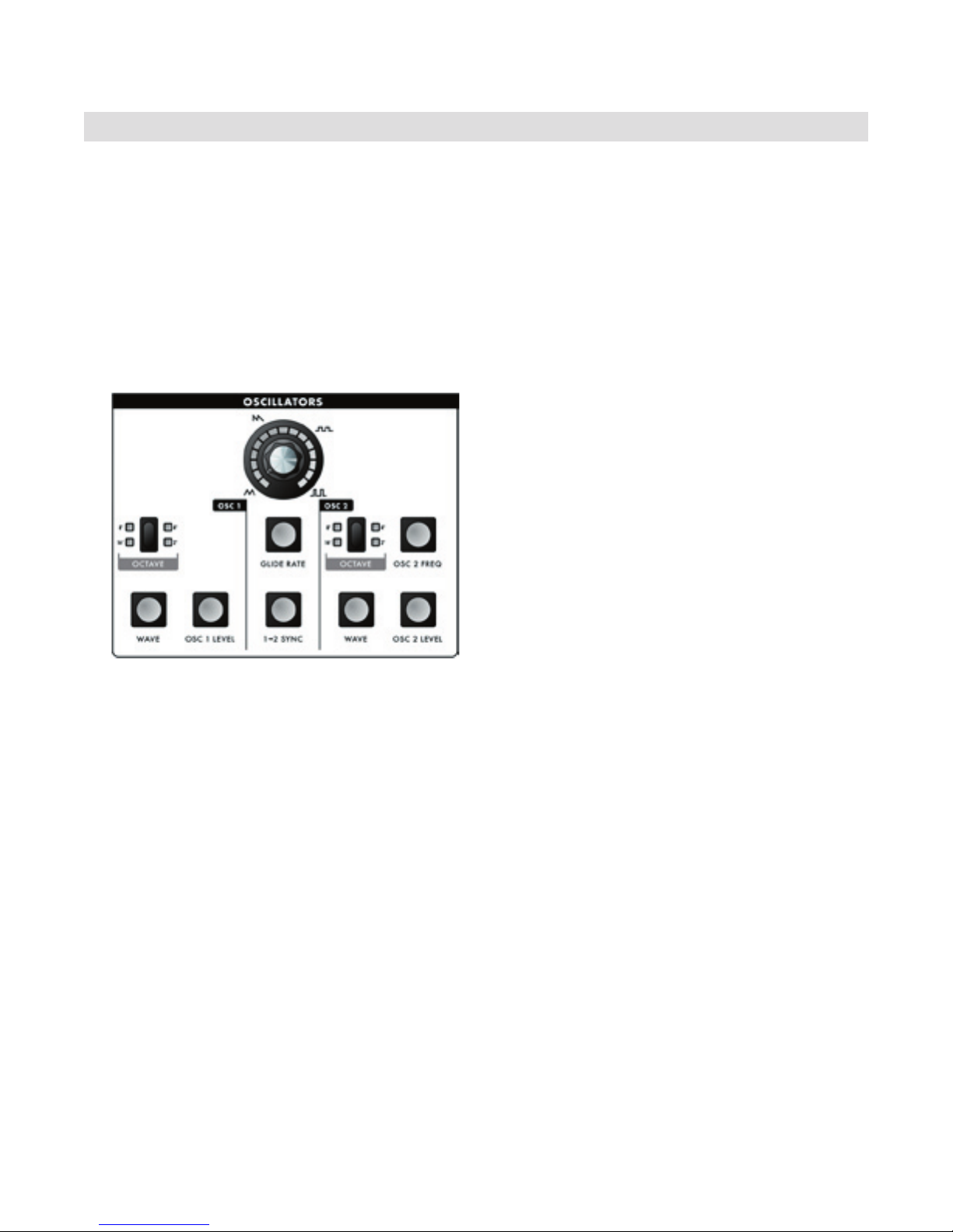
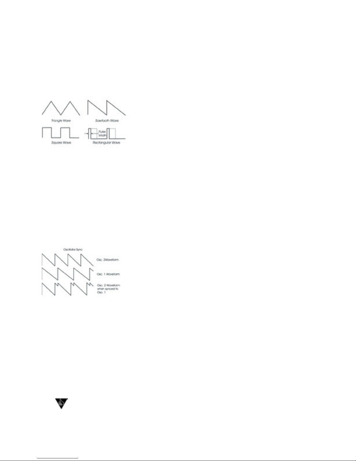
Waveform:
Each oscillator has a switch labeled WAVE that allows the analog edit control to modify the waveform.
The waveform is continuously variable from triangle, to sawtooth, to square, to rectangular. The waveform
is morphed gradually from one to another as the value control is rotated. The legend around the analog edit
control for the oscillator section indicates the knob positions to obtain the triangle, sawtooth, square and
skinniest pulse waveforms. Because the waveform is voltage controlled, this parameter can be modulated.
This allows the generation of some very interesting timbral changes.
By limiting the modulation between the square and thin rectangle
(pulse) waves, you can get pulse width modulation, a classic analog
synthesizer sound. Although the waveforms can be set from the
front panel individually for each oscillator, modulation is applied to
both waveform controls simultaneously. When using modulation, it is
possible to make the width of the rectangular wave so skinny that it
becomes silent.
Sync:
In the center of the oscillator panel is a switch labeled 1–2 SYNC. This is an ON/OFF type switch that
has no interaction with the analog edit control. Sync is ON when the 1-2 SYNC switch is lit. With sync on,
Oscillator 2 is synchronized (synced) to Oscillator 1, forcing Oscillator 2 to restart its waveform from the
beginning each time Oscillator 1 starts a new waveform cycle. The
effect is noticeable if the synced Oscillator is a higher frequency than
the Reset Oscillator. The main frequency heard is that of the reset os-
cillator. As the frequency of the synced oscillator is swept, it reinforces
the harmonics of the reset oscillator. Use the Oscillator 2 Frequency
control to hear this effect. Depending on how applied, the effect can
be aggressive or warm and vocal.
Frequency:
Oscillator 2 has a switch labeled OSC 2 FREQ that allows the analog edit control to adjust the frequency
of Oscillator 2 relative to Oscillator 1. The pitch of Oscillator 2 can be adjusted up or down 7 semitones
(+/- a fth). By changing the pitch of Oscillator 2, more than one frequency can be played when a key is
pressed, creating intervals for large adjustments, or to get a chorus sound when the oscillators are just
slightly out of tune. Note that Oscillator 1 does not have a frequency control because it is designed to serve
as a reference oscillator.
Glide Rate:
In the center of the oscillator panel is a switch labeled GLIDE RATE. When this is selected, the analog edit
control is used to set the glide rate (portamento) between notes. A Glide switch on the User Interface
panel (on the far left) turns the Glide effect on or off. Glide is the time it takes to go from one note to the
next. The glide rate can vary from virtually instantaneous to a very slow glide (about 5 seconds to go from
the lowest C to the highest C on the keyboard).
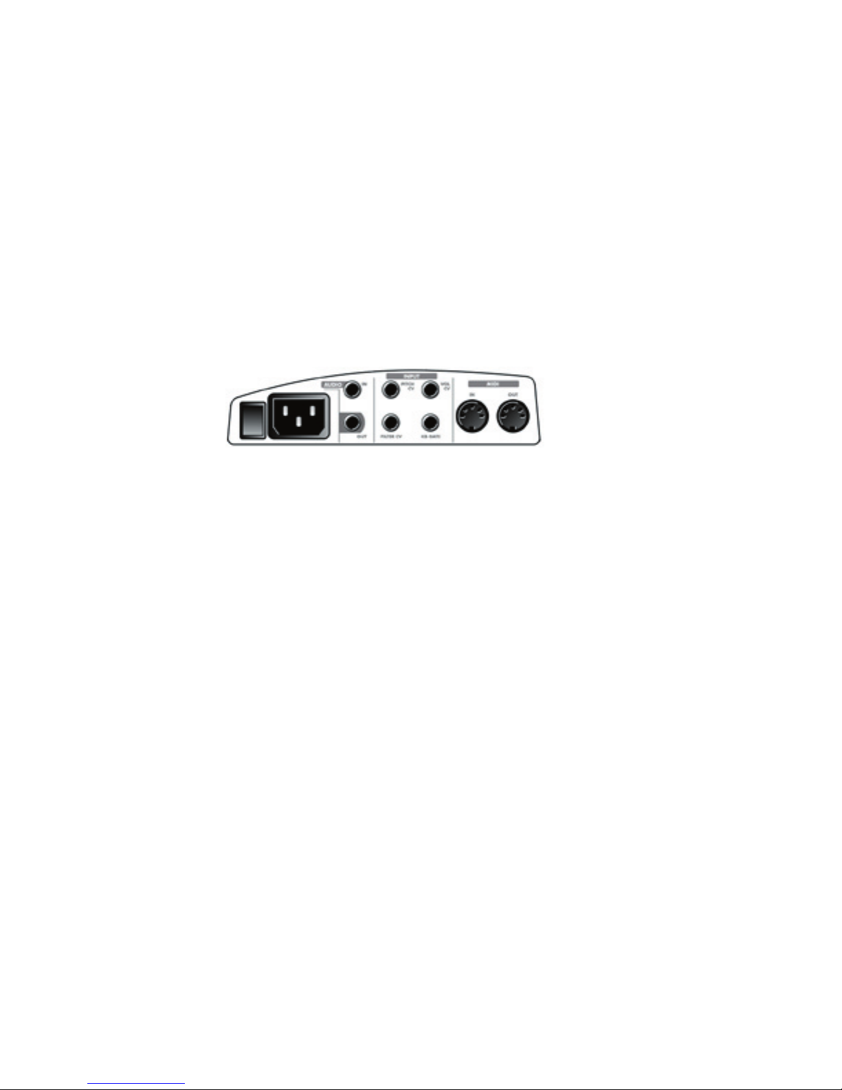
Additional CV control:
The PITCH jack on the side-panel is a CV input for external control of the oscillator pitch. This input con-
trols the frequencies of both oscillators. A 1-volt change of this voltage will change the pitch by NOMINAL-
LY one octave. The jack accepts -5 to +5 volts, or an expression pedal like the EP-1.
PERFORMANCE TIP: A steady control voltage applied to the PITCH jack will offset the base
pitch of both oscillators. You can use this feature to transpose the keyboard to any desired
interval applying the appropriate steady-state CV. See Appendix E for more information on
how to congure this.