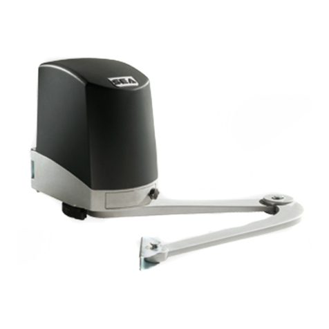
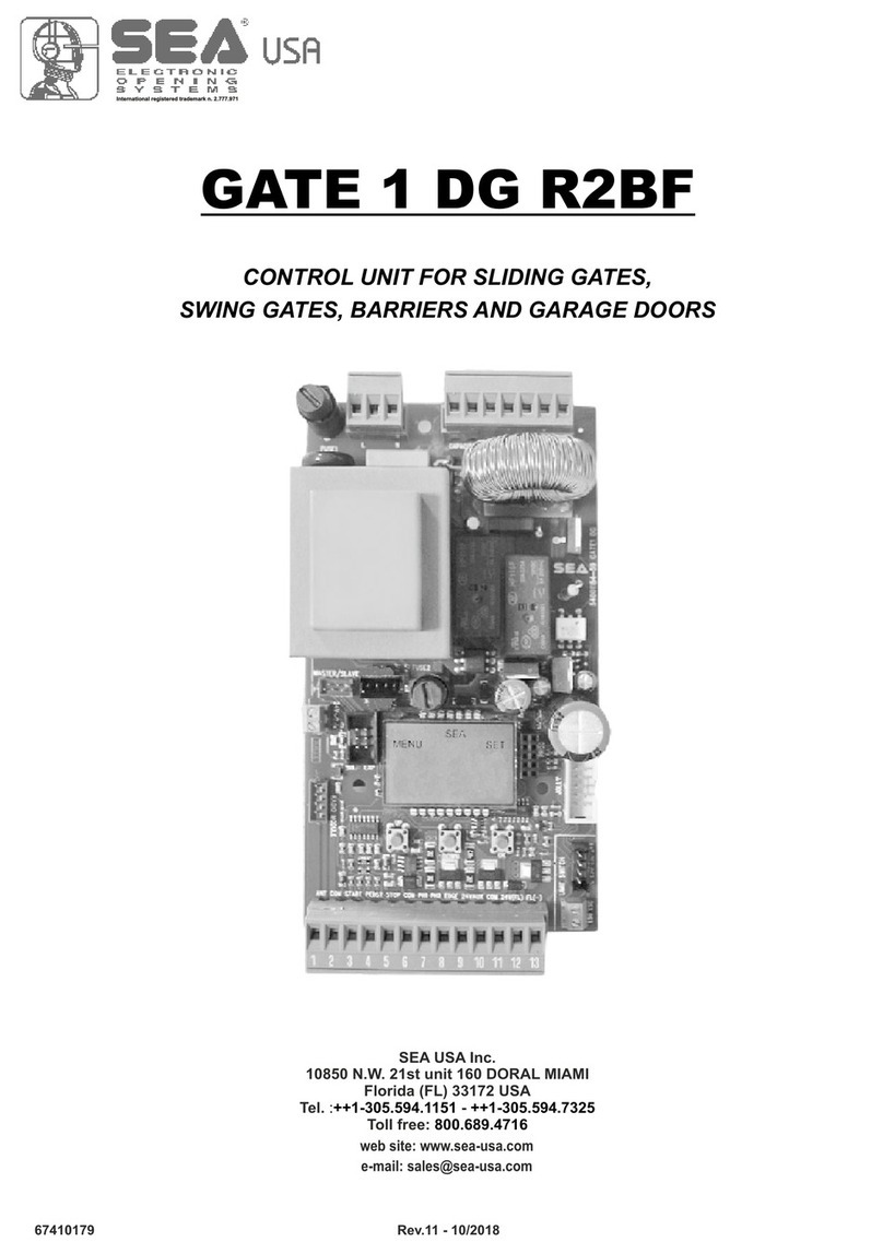
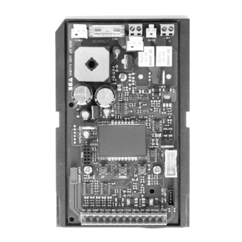
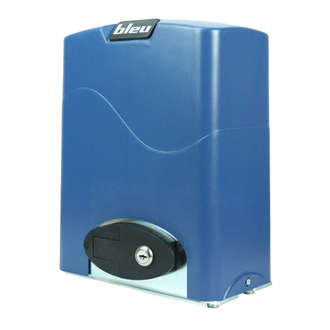
SEA B 100 PLUS 1000N User manual

English
Operators for garage doors
Imported by SEA S.p.A.
Zona industriale 64020 S.ATTO Teramo - (ITALY)
Tel. +39 0861 588341 r.a. Fax +39 0861 588344
www.bleuteam.it
REV 00 - 12/2014
INSTALLATION MANUAL
B 100 PLUS
600N
B 100 PLUS
1000N

English
INDEX
1. FUNCTION DESCRIPTION.....................................................................................3
2. OPENER PACKAGE CONTENTS..........................................................................5
3. IMPORTANT INSTALLATION INSTRUCTION ..............................................................6
4. INSTALLATION STEPS.................................................................................................7
4-1. MEASURE DOOR’S HIGHEST TRAVEL POINT......................................................7
4-2. INSTALL HEADER BRACKET............................ ....................................................7
4-3. INSTALL DOOR BRACKET TO DOOR.................................................... ... ........8
4-4. ATTACH RAILTO OPENER HEAD...........................................................................8
4-5. ATTACH RAIL TO HEADER BRACKET....................................................................9
4-6. MOUNT OPENER TO CEILING......................... ..................................................9
4-7. CONNECTARM TO DOOR AND TROLLEY...................................................... 10
4-8. CHECK EMERGENCY RELEASE..........................................................................10
4-9. TENSION ADJUST ................................................................................................11
4-10. RAIL INSTALLATION.................. ..........................................................................11
5. CONTROL UNIT.......................................................................................................12
5-1. SAFETY AND CONTROL DEVICES CONNEXION......................13
5-2. CONTROL UNIT PROGRAMMING...............................................................13
5-3.TRANSMITTERS MEMORIZATION ................................................................13
5-4. RUN LEARNING.....................................................................14
5-5. THE ADJUSTMENT OF REVERSE FORCE .......................................................1. 4
5-6. USE PHOTOELECTRIC SWITCHES ..........................................................15
5-7. USE AUTOMATICALLY-CLOSING FUNCTION................................................. 15
6. TROUBLE SHOOTING ........................................................................................16
7. GENERAL NOTICE FOR THE INSTALLER AND THE USER .......................................17
REV 00 - 12/20142

In the event of a power cut all data remains permanently saved in the
program memory.
(End points, registered transmitters and the last position of the door.)
English
TECHNICAL DATA
TX Frequency:
230V/50Hz
140 170
120
4
600 1000
120
4
Standard
IP20
-20°C to +60°C
433.92 MHz
1. Functional description
The B 100 Plus 600N and B 100 Plus 1000N operators may be used for sectional doors.
Supply voltage:
Power(W):
Door (travel) speed(mm/s):
Maximum duty cycle(min):
Pulling force(N):
Internal release mechanism:
Protection category:
Permissible ambient temperature:
Data conservation:
Soft start
This function is integrated as a standard feature and guarantees a slow starting movement of the door.
Soft stop
With the aid of this function, the opener can slow down before reaching the final position.
Logic: OPEN - STOP - CLOSE - STOP - OPEN.
Additional connecting options for external accessories
In addition you can connect up external push buttons such as internal buttons, key switches and a wicket door contact.
Profile slide carriage
“Closed”
end position
“Open”
end position
Recognition of obstructions
The door opener has an automatic obstruction-recognition system (through internal monitoring of power).
If the door encounters an obstruction when closing or opening, the door opener stops the door automatically and moves it
approximately 10 cm in the opposite direction.
After removing the obstruction you can operate the garage door opener normally again.
REV 00 - 12/2014 3
B 100 PLUS
600N
B 100 PLUS
1000N

Internal release mechanism:
The models have an internal release mechanism with which you can open the garage door by hand in emergencies or in the event of
a power cut.
The internal release mechanism is attached to the profile slide with a rope and a knob. By pulling the rope you uncouple the garage
door from the opener and then you can open the door by hand.
It is suggested to:
• Close or open the door fully after each release.
• The emergency release is not intended for “everyday use”, since it is an emergency device..
Internal
release
mechanism
English
Rail and operators’ size
REV 00 - 12/20144

2. Opener package contents
The following items are included with the Garage Door Opener. The opener and rail are packaged with their respective
carton.
English
(A) OPENER
(B)ACCESSOIRES
a. Wall Bracket (1x)
b.D. oor Braket & Plate (1x)
c. U Bracket (3x)
e. Clevis (1x)
f. Clevis (1x)
g. Cotter pin (3x)
h. Hex nut (1x)
i. Hex bolts (1x)
k. Hex Head Driving Screw (4x)
(C) Straight DoorArm
(D) Curved DoorArm
(F) Rail
REV 00 - 12/2014 5

3. Important installation instructions
WARNING
1. READ AND FOLLOW ALL INSTALLATION INSTRUCTIONS
2. Check with the door manufacturer to determine if additional reinforcement is required to support the door prior to
installation of the garage door opener.
3. Install garage door opener only on a properly balanced garage door .An improperly balanced door could cause
seriously injury. Have a qualified service person make repairs to garage door cables, spring assemblies, and other
hardware before installing the opener.
4. Remove all ropes and disable all locks connected to the garage door before installing opener.
6.
After installing the opener, test Safety Reversal System. Door MUST reverse when touching an obstacle, within the
time and ways described in the regulations.
English
5. Do not connect the opener source of power until you have performed all the steps of these instructions.
7. Once a year: keep well lubricated rollers of the door, the hooks and the bearings following the instructions or
contacting a maintenance company.
REV 00 - 12/20146

4. INSTALLATION STEPS
Identify a sound structural support on header wall above garage door for header bracket mounting.
Fasten it securely using lag screws (not provided) to structural supports of garage.
4-1. Measure door’s highest travel point:
• Open door to its highest travel point and measure from the garage floor to the top of door.
• Write down this distance.
Add 30mm to the door travel height (measured above).
English
4-2. Install header bracket
! WARNING!
If the header bracket is not rigidly fastened to a sound structural support on the header wall or ceiling, the safety
reverse system may not work and could cause accidents and serious injuries. DO NOT move or adjust springs or
garage door hardware, as these parts are under extreme tension and could cause accidents or serious injuries.
REV 00 - 12/2014 7

4-3. Install door bracket to door
Mark the position of the holes and fix the anchor bracket to the upper end of the door with screws (not supplied).
4-4. Attach rail to opener head
!WARNING!
When fastening the rail to the opener, use only the screws provided. Use of any other screws may result in
opener falling from ceiling and causing damage to persons or property in the garage.
• Position rail onto opener chassis by lining up rail sprocket opening with motor head shaft (see drawing 4-4-1).
Make sure shaft engages teeth inside rail sprocket.
• Position 2 “C” rail clips over rail and onto chassis. Flanges on “C” rail clips MUST fit into guide posts recesses (see
drawing 4-4-2)
English
• Insert screws (k) through bracket holes and into chassis holes, and tighten screws firmly to hold rail to head (see
drawing 4-4-3).
4-4-1 4-4-2 4-4-3
REV 00 - 12/20148

4-5. Attach rail to header bracket
• Support opener head slightly off the floor.
• Lift the opposite end of the rail up to the header bracket.
• Position rail end-stop within the openings in the header bracket. Insert clevis (e), and then attach cotter pin (g) to
end of pin.
English
4-6. Mount opener to ceiling
!WARNING!
If not properly secured, the operator could fall and injure someone. Secure opener to structural supports or framing. Do
not mount to drywall, plaster, or other such material.
• Position opener head so that rail is lined up with center line of open door.
• Line up hanger brackets (not provided) with ceiling joists or framing to locate where brackets are to be fastened.
With two screws, 2 nuts and a u-shaped hoop will orbit on fixed to a hanger.
REV 00 - 12/2014 9

4-7. Connect arm to door and trolley
• Make sure door is fully closed.
• Pull the manual release cord on the trolley to disconnect trolley from chain or belt connector.
Slide trolley to position it about 100mm-200mm away from the door.
• Will push-pull crotch fixed on the door fittings, see figure.
Fig.4-7-1
English
• After connecting appropriate door arm, ensure trolley is disengaged. Check for proper door operation by manually
lifting then lowering to fully opened and closed positions.
• Readjust door arm if needed.
Pull down on release knob to lock trolley, then move door manually until trolley locks with chain or belt connector.
4-8. Check emergency release
!WARNING!
Use extreme care when pulling release knob. DO NOT use knob to pull door open or closed. Except for
emergency situations, use knob only when door is closed.
The emergency release cord with red knob, which is already attached to the trolley, is extremely important parts
of the operator system; see drawing 4-7-1, pulling the release cord disengages the door from the opener. This
allows the door to be moved manually up and down independent of the opener motor.
If the door is in the open position, use extreme care when using the release.
Use emergency release to disconnect the door if the power is out. It should also be used if for some unforeseen reason
the door strikes a person or object during its travel and does not automatically reverse off the obstruction.
To release door- pull firm ly down on red knob.
Prior to re-engaging door, ensure that all obstructions are removed and door is operating properly manually. Before
re-engaging trolley with a chain or belt connector, pull down knob again, then release. The red catch will stop in the
“lock” position and will open indicator window. Now the door can be reconnected by moving it manually and bringing
it into position when the connector is inside of the trolley.
REV 00 - 12/201410

4-9. Tension adjust
The tension, can the adjusting screw clockwise until brush and the rail has the right position.
English
4-10. Rail installation
1 , 2 Rail end, 3 4 Rail, 5 Slider, 6 B , 7
8 9 chain, 10 11 12 13 14
15 16 17 18
Lock nut Party neck bolt, lock Self-tapping screws,
spring, Pulley block, Slippery wheel, pulley, bars, Shake hands
handle, Spring, Link head, Sprocket stents, Sprocket
REV 00 - 12/2014 11

5. Control unit
CN1
CNE
CNR
SD
MR
ML
POWER LIGHT
BATTERY
DISPLAY
RECEPTOR
+ -
+24V PB GND
PBSW
+ Allarm -
A-SW
CN1 = Input/output connector
CNE = Encoder connector
CNR = External receiver connector
SD = Door contact
MR = Right motor
ML = Left motor
POWER = Power supply connector
BATTERY = Battery connector
LIGHT = Courtesy light connector
DISPLAY = Display connector
English
REV 00 - 12/201412

WAL L
SWITCH
English
5-1. Control and safety devices connection
wiring method: CN1
PUSH
GND
SAFETY
+24V
TXRX
+24V
PB
GND
PBSW
Function logic:
OPEN - STOP - CLOSE - STOP - OPEN.
Note:
+24V accessoires power supply
GND accessoires negative
PB photocells contact
PBSW START contact
5-2. Control unit programming
5-3. TX Memorization
If you need to learn another remote control, reprogram as the step 1), the opener can study 20 remote controls at most.
2) TX Cancellation
Powering the unit you may see scrolling
the numbers from 9 to 1 on the display. If
the numbers appear reversed,
immediately press the button setting and
the numbers will be reversed and
displayed in the correct manner.
Press and keep pressed “CODE”
until the decimal point “.” is bright
and then off automatically.
Release “CODE”, all
memories are erased.
1)
Press “CODE” over one second,
until the LED display dot “.”, is
brightened.
Press any button of remote control once,
the decimal point “.” is off automatically.
Press this remote control buttons again, the dot“.” flashes quickly.
After the decimal point“.” off, which indicates the successful
learning of remote control.
Suggestions: For the sake of safety, once the remote control is lost, please erase all the memories of remote control,
and study it again.
REV 00 - 12/2014 13

English
5-4. Run learning
Press “SETTING” over 4 seconds
until the LED displays the letter “1”.
It turns into opening position learn
state.
Press “+” (OPEN)
until the door is not in
the desired open
position.
During this phase the
display displays the
letter “n”..
When the door reaches to the desired
position, leave “+” press “SETTING” to
confirm the opening position. The
LED displays the letter “2”. It turns into
closing position learn state.
Press “-” (CLOSE),until the door is
not in the desired closed position.
During this phase the display
displays the letter “u”..
When the door reaches to the desirable position, leave
press “SETTING” to confirm the closing position. After
finishing setting, the LED will display “ll”, and the door
can operate normally.
“-
”
NOTE: and the door moves in closing, exchange the motor cables.If press button “+”
Press “SETTING” until the LED displays
the letter “3” and release button.
Use “+” (OPEN) to increase
the force, press“-” (CLOSE) to decrease.
The LED displays the of setting.value
Once found the right value, press SETTING to
confirm. After finishing setting, the LED displays
“ll”.
5-5. The adjustment of reverse force
REV 00 - 12/201414

5-6. Use photoelectric switches
The photocell input can be disabled through the display.
English
If you want the photocell active, press "+" (OPEN) until
the LED displays "H".
If you want the photocell not active, press the "-"
(CLOSE), the LED displays "II".
When finishing the setting, press “SETTING” to quit,
digital shows “II”.
5-7. Use automatically-closing function
Press “+” (OPEN) over 4 seconds,
the LED displays “-”, you can set
Automatically–closing function.
Press “+” (OPEN), or “-” (CLOSE)
to adjust automatically closing
time.
When set up is completed, press
“SETTING” to confirm and exit.
Emergency stop
connection
It is possible to connect on
the CN2 terminal a battery
for the emergency
operation. Connect a 12V
max 2Ah battery (charge
current 150mA).
The closing time will vary
from 1 to 9 min. in steps of 1
min.
"0" indicates that the
automatic reclosing is
OFF.
Press “-” (CLOSE) over 4 seconds until
the LED displays “-”, you can set the he
status of the photocells.
REV 00 - 12/2014 15

6. Trouble shooting
Fault Cause Solution
English
Check the electrical
outlet and/or the
powder supply fuse
Re-adjust the journey
No response for the
operator, LED is off
Disconnection between
door opener and power
supply
No response for the
operator
The journey adjustment
is wrong
While opening or closing
doors, it stops in the
middle on its way, or
runs at opposite way
The door operating
resistance is stronger
than the set force
- Check the balance
system of the door
- Readjust the opener to
increase the load force
of the door
The door cannot be
closed
The photoelectric switch
is sheltered from the
obstacle
The photoelectric is
not connected
Remove the obstacle
Connected the
photoelectric
The door cannot be
opened or closed
completely
The journey of the door
is adjusted
inappropriately
Re-adjust the journey
of door opener
REV 00 - 12/201416

English
7. GENERAL NOTICE FOR THE INSTALLER AND THE USER
1. Read carefully these Instructions before beginning to install the product. Store these instructions for future
reference.
2. Don’t waste product packaging materials and /or circuits.
3. This product was designed and built strictly for the use indicated in this documentation. Any other use, not
expressly indicated here, could compromise the good condition/operation of the product and/or be a source of
danger. BLEU by SEA declines all liability caused by improper use or different use in respect to the intended
one.
4. Once installed, the products BLEU by SEA must comply with the Machinery Directive (2006/42/EC and
subsequent amendments).
Installation must be done respecting Directives: EN12453 and En12445.
5. Do not install the equipment in an explosive atmosphere.
6. BLEU by SEA is not responsible for failure to observe Good Techniques in the construction of the locking
elements to motorize, or for any deformation that may occur during use.
7. Before attempting any job on the system, cut out electrical power and disconnect the batteries. Be sure that
the earthing system is perfectly constructed, and connect it metal parts of the lock.
8. Use of the indicator-light is recommended for every system, as well as a warning sign well-fixed to the frame
structure.
9. BLEU by SEA declines all liability as concerns the automated system’s security and efficiency, if
components used, are not produced by BLEU by SEA.
10. For maintenance, strictly use original parts by BLEU by SEA.
11. Do not modify in any way the components of the automated system.
12. The installer shall supply all information concerning system’s manual functioning in case of emergency,
and shall hand over to the user the warnings handbook supplied with the product.
13. Do not allow children or adults to stay near the product while it is operating. The application cannot be used
by children, by people with reduced physical, mental or sensorial capacity, or by people without experience or
necessary training. Keep remote controls or other pulse generators away from children, to prevent involuntary
activation of the system.
14. Transit through the leaves is allowed only when the gate is fully open.
15. The User must not attempt to repair or to take direct action on the system and must solely contact qualified
BLEU by SEA personnel or BLEU by SEA service centers. User can apply only the manual function of
emergency.
16. The power cables maximum length between the central engine and motors should not be greater than 10
2
m. Use cables with 2,5 mm section. Use double insulation cable (cable sheath) to the immediate vicinity of the
terminals, in particular for the 230V cable. Keep an adequate distance (at least 2.5 mm in air), between the
conductors in low voltage (230V) and the conductors in low voltage safety (SELV) or use an appropriate sheath
that provides extra insulation having a thickness of 1 mm.
REV 00 - 12/2014 17

Sistemi Elettronici
di Apertura Porte e Cancelli
International registered trademark n. 804888
®
REV 00 - 12/201418
Dichiarazione di conformità
Declaration of Conformity
Prodotto: B 100 PLUS 600N - B 100 PLUS 1000N
Importato da paesi extra UE da:
Imported by extra UE countries by:
SEAS.p.A.
Zona industriale 64020 S.ATTO Teramo - (ITALY)
Tel. +39 0861 588341 r.a. Fax +39 0861 588344
La SEA S.p.A. dichiara che i prodotti sopra citati sono conformi ai requisiti essenziali di sicurezza relativi
ai prodotti entro il campo di applicabilità delle seguenti Direttive Comunitarie:
SEA S.p.A. declares that the above mentioned products are conforming to the essential safety
requirements related to the product within the field of applicability of the following Community Directives:
- Direttiva 2006/42/CE Direttiva macchine (allegato I)
Directive 2006/42/CE Machinery Directive (annex I)
- Direttiva 2004/108/CE Direttiva compatibilità elettromagnetica
Directive 2004/108/CE Electromagnetic compatibility
• CEI EN55014-1 Emissioni condotte e radiate
IEC EN55014-1 Conducted and radiated emissions
• CEI EN55014-2 Prove di immunità
IEC EN55014-2 Magnetic field immunity
- Direttiva 2006/95/CE - Direttiva Bassa Tensione
Directive 2006/95/CE - Low voltage Directive
• CEI EN60335-1:2008 Sicurezza degli apparecchi elettrici d’uso domestico e similare (Requisiti
Generali).
IEC EN60335-1:2008 Houseold and similar electrical appliances - Safety - Part one: general
requirements.
(Luogo, data di emissione) L’Amministratore
(Place, date of issue) The Administrator
Teramo, 23/12/2014 Ennio Di Saverio
http://www.seateam.com


Imported by SEA S.p.A.
Zona industriale 64020 S.ATTO Teramo - (ITALY)
Tel. +39 0861 588341 r.a. Fax +39 0861 588344
www.bleuteam.it
This manual suits for next models
1
Table of contents
Other SEA Garage Door Opener manuals
Popular Garage Door Opener manuals by other brands
Automatic Technology
Automatic Technology GDO-6 EasyRoller owner's manual

SOMFY
SOMFY Elixo 500 230 V installation manual

Steel-Line
Steel-Line SD800 Installation and operating instructions

Wisniowski
Wisniowski AWso2018 Assembly and operating instructions
B&D
B&D Series 2 Firmadoor installation instructions
Chamberlain
Chamberlain T quick start guide
