Mopar 82212501 User manual

1
RHBNAVIGATIONRADIOKIT
WRANGLER
CALLOUTDESCRIPTIONQUANTITY
1Harness1
2Antenna1
3RHBRadio1
4ZipTies10
TOOLSREQUIRED
10mmSocket(1/4in
Drive)
1/4DriveRatchetPhillipsHeadScrew
Driver
FiberTrimStick1/4DriveTorque
Wrench
PROCEDURESTEPS:
Vehiclebeingupgradedfrom(AM/FMonly)youwillneedtodothefollowing:
•RADIOREPLACEMENT
•SDARS/NAVIGATIONANTENNACABLEANDANTENNAINSTALLATION
Vehiclebeingupgradedfrom(AM/FMandSATELLITEAudio(SDARS))youwillneedtodothefollowing:
•RADIOREPLACEMENT
•ANTENNAREPLACEMENT
Dec31,2010K6861157Rev.1

2
RADIOREPLACEMENT
1.Disconnectandisolatethenegativebatterycable.
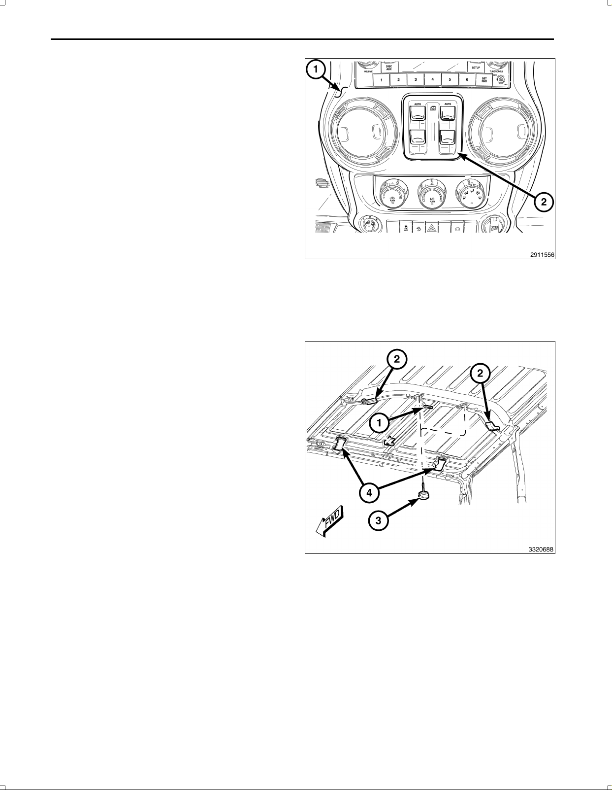
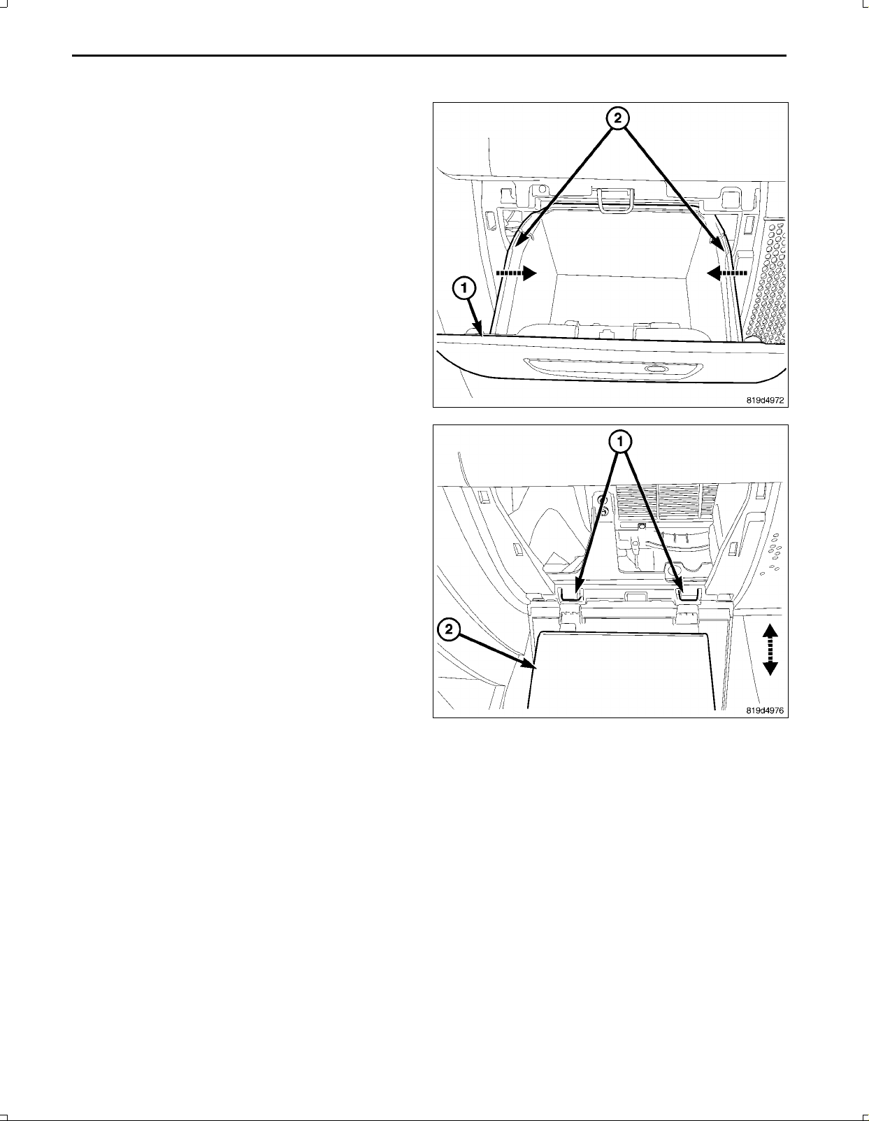
2.Ifequippedwithpowerwindows,usingafibertrim
stick,gentlyprytheswitchassembly(2)awayfrom
thetrimpanel(1),disconnecttheelectricalconnector
andremovetheswitch.
3.Forvehicleswithoutpowerwindows,usingafibertrim
stick,gentlyprythestoragebinassemblyawayfrom
thebezelandremovethebin.
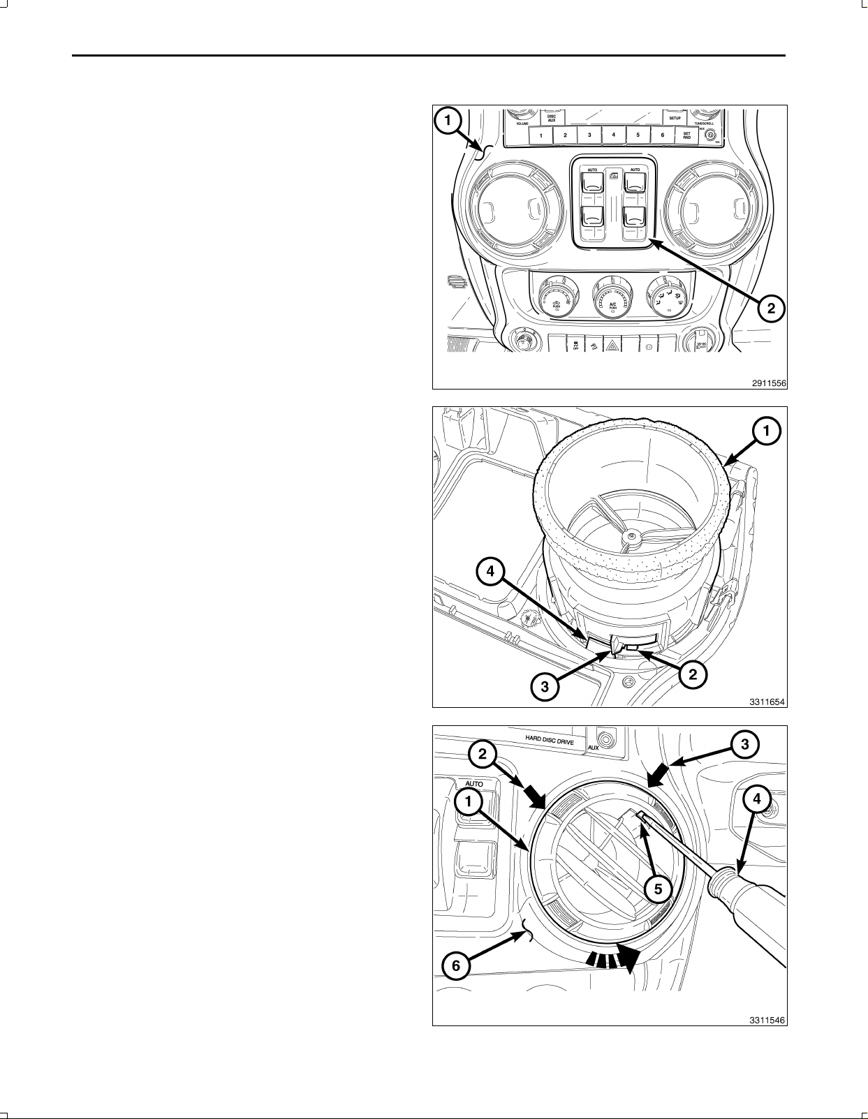
4.Eachairoutlet(1)issecuredbyaretainingtab(3)lo
catedontheoutlet,andastoptab(4)locatedonthe
backofthetrimpanel.Accesstheretainingtabfrom
theinsideoftheairoutlet,throughthesquareopen
ings(2)provided.
NOTE:Centerrightoutletshown.Otheroutletsimilar.
5.Rotatethelouversofbothairoutlets(1)inthecenter
oftheinstrumentpanel(6)totheelevenoclockposi
tion(2).
6.Placeasmallscrewdriver(4)orequivalentthroughthe
squareopening(5)insideofeachairoutlet,locatedat
thetwelvethirtyposition(3).
7.Carefullyprytheretainingtab(3,showninprevious
illustration)towardthecenteroftheairoutletandro
tatetheoutletscounterclockwise.
8.Removetheairoutletsfromthetrimpanel.
Dec31,2010K6861157Rev.1

3
9.Usingafibertrimstick,disengagethetworetaining
clips(1)thatsecurethetopofthesteeringcolumn
openingcover(2)totheinstrumentpanel.
10.Disengagethetwolowerretainingtabsandremove
thesteeringcolumnopeningcover.
11.Removethestoragebinmatandthescrew(1),lo
catedatthetopoftheinstrumentpanel.
12.Removethescrew(2)throughthecenteropeningof
thetrimpanel.
13.Removethetwoscrews(3)thatsecurethetrimpanel
totheinstrumentpanel,locatedatthesteeringcolumn
opening.
CAUTION:Donotuseanytoolstoreleasethelower
trimpanelretainingclips.Failuretofollowthesein
structionscanresultindamagetothetrimpaneland
reinforcement.
14.Releasethesixlowerretainingclips(3)withoutthe
useoftools.Reachintotheinstrumentpanelthrough
theventopenings(1),firmlygraspthereinforcement
locatedbehindthetrimpanel(2)andcarefullypullthe
reinforcementandtrimpanelassemblyrearward.
Dec31,2010K6861157Rev.1

4
15.Releasetheremaining13retainingclips(1)andre
movethetrimpanel(2).
CAUTION:Pullingtheantennacablestraightoutofthe
radiowithoutpullingonthelockingantennaconnec
torcoulddamagethecableorradio.
16.Removetheradiomountingscrews.
17.Pulltheradiooutfarenoughtoaccessthebackofthe
radio.
18.DisconnecttheAM/FMantenna(2)andelectricalcon
nectors(1).
19.Ifequipped,disconnectthenavigationantenna(3).
20.Ifequipped,disconnecttheUSBconnectors(4).
21.Removetheradiofromtheinstrumentpanel.
22.Positionthenewradiototheinstrumentpanel.
23.ConnecttheAM/FMantenna(2)andelectricalcon
nectors(1).
24.Connectthesatellite/navigationantenna(3).
25.Ifequipped,connecttheUSBconnectors(4).
26.Installtheradiomountingscrews.
27.Positionthetrimpanel(2)intoplaceandfullyseatall
19retainingclips(1).
Dec31,2010K6861157Rev.1

5
28.Installthetwoscrews(3)thatsecurethetrimpanelto
theinstrumentpanel,locatedatthesteeringcolumn
opening.
29.Installthescrew(2)throughthecenteropeningofthe
trimpanel.
30.Installthescrewandthestoragebinmatatthecenter
oftheinstrumentpanel.
31.Positionthesteeringcolumnopeningcover(2)tothe
instrumentpanelandengagethetwolowerretaining
tabs.
32.Engagethetworetainingclips(1)thatsecurethetop
ofthesteeringcolumnopeningcovertotheinstrument
panel.
NOTE:Centerrightoutletshown.Otheroutletsimilar.
NOTE:Ifafoamsealonanairoutletisdeformedor
damaged,thesealmustbereplaced.
33.Installtheairoutlets(1)intothetrimpanel(2)andro
tatetheairoutletsclockwiseuntilfullyengaged.
Dec31,2010K6861157Rev.1

6
34.Ifequippedwithpowerwindows,positiontheswitch
assembly(2)tothetrimpanel(1),connecttheelectri
calconnectorandinstalltheswitch.
35.Forvehicleswithoutpowerwindows,installthestor
agebinassembly.
36.Reconnectthenegativebatterycable.
SDARS/NAVIGATIONANTENNACABLEANDANTENNAINSTALLATION
HARDTOP
CAUTION:Becertainallfastenersareremoved.Failuretofollowtheseinstructionswillresultinhardtopdam
age.
1.Frominsidethevehicle,releasethecenterclamps(1).
2.Releasetherearclamps(2).
3.Removetherearthumbbolts(3).
4.Releasethefronttopclamps(4).
Dec31,2010K6861157Rev.1

7
5.Fromthehardtop(1)leftrearcorner,oftheinterior,
disconnectthehardtopwireharnessconnector(2).
6.Disconnectthehardtopwasherhosefromtherear
washernozzlenipple(3).
7.Removethemodulartops(1)and(2).
8.Onfourdoormodels,removethetwofrontbolts(3).
CAUTION:Liftingthemainhardtoponoroffwillre
quiretheassistanceoffourpeople,oneineachcor
ner.Failuretoliftthetopasinstructedmayresultin
hardtopdamage.
9.Removethesixsidebolts(5).Removethemainhard
top(4)byliftingevenly,steadilyandwithoutflexing.
SOFTTOP
1.Foldthesofttop(1)downtoexposethepassenger
upperBpillarsupport.
Dec31,2010K6861157Rev.1

8
AllModels
1.Opentheglovebox(1)andsqueezethestoptabs(2)
inward.
2.Lowertheglovebox(2)andreleasethehinges(1)and
removetheglovebox.
Dec31,2010K6861157Rev.1

9
TWODOOR
1.Usingafibertrimstick,separatetheretainingclips(1)
andremovetheuppertrim(2).
2.Removethepushpinfasteners(5).
3.Separatetheretainingclips(4)andremovethelower
Bpillartrim.
FOURDOOR
1.Removetheseatbeltturningloop(2).
Dec31,2010K6861157Rev.1

10
2.Removethebolt(2)anddisconnecttheseatbelt(3)
fromtheseat(1).
3.Usingafibertrimstick,separatetheretainingclips(2)
andremovetheupperBpillartrimpanel(1).
4.Removethepushpinfasteners(3)andseparatethe
lowerBpillartrimpanel(2).
5.Pulltheseatbelt(1)throughtheslotinthetrim(2)and
removethetrim.
Dec31,2010K6861157Rev.1

11
ALLMODELS
1.Removethepushpinfastener(3)andseparatethe
retainingclips(1).
2.Removethecowltrim(2).
3.Routetheantennacable(1)fromtheradioopening
alongthegloveboxopening.
4.ContinueroutingalongthescuffplateanduptheBpil
lartotheantennamountinglocation.
5.Disconnecttheantennaconnector(1).
6.Removetheantennafastenerandremoveantenna
(2).
7.Installthenewantenna(2).Tightentheantennare
tainerto9N∙m(80in.lbs.).
8.Connecttheantennaconnector(1).
Dec31,2010K6861157Rev.1

12
9.Positionthetrim(2)intoplaceandseatthepushpin
fasteners(1)fully.
10.Installthepushpinfastener(3).
TWODOOR
1.InstallthelowerBpillartrim(3)andseattheclips(4)
fully.
2.Installthepushpinfasteners(5).
3.InstalltheupperBpillartrim(2)andseattheclips(1)
fully.
FOURDOOR
1.Pulltheseatbelt(1)throughthelowerBpillartrim(2)
andpositionintoplace.
2.Seattheclipsfullyandinstallthepushpinfasteners
(3).
Dec31,2010K6861157Rev.1

13
3.PositiontheupperBpillartrim(1)intoplaceandseat
theclips(2)fully.
4.Positiontheseatbeltturningloop(2)ontotheheight
adjuster(1)ontheuppersportbar.Becertainthat
theseatbeltwebbingbetweentheretractorandthe
turningloopisnottwisted.
5.Installandtightenthescrew(3)thatsecurestheturn
inglooptotheheightadjuster.Tightenthescrewto
40N∙m(30ft.lbs.).
6.Engagetheupperedgeofanewtrimcover(4)over
thetopoftheturningloop.Thensqueezethelower
endofthetrimcoverandtheturninglooptogether
firmlyandevenlyuntiltheengagementtabsofthetrim
coversnapintotheslotsoftheturningloop.
7.Positiontheseatbelt(3)loweranchortothemounting
holeontheoutboardsideofthefrontseat(1)cushion
frame.Becertainthattheseatbeltwebbingbetween
theturningloopandtheloweranchorisnottwisted.
8.Installandtightenthescrew(2)thatsecuresthelower
anchortotheseat.Tightenthescrewto40N∙m(30
ft.lbs.).
Dec31,2010K6861157Rev.1

14
ALLMODELS
1.Positionthegloveboxtabsontothehinges(1).
2.Closethebox(1)andsqueezethestoptabs(2)in
wardandengageintotheinstrumentpanel.
Dec31,2010K6861157Rev.1

15
SOFTTOP
Foldthesofttop(1)backintoposition.
HARDTOP
CAUTION:Liftingthemainhardtoponoroffwillre
quiretheassistanceoffourpeople,oneineachcor
ner.Failuretoliftthetopasinstructedmayresultin
hardtopdamage.
1.Installthemainhardtop(4)byliftingevenly,steadily
andwithoutflexing.Placeontothevehiclewhilelining
upthealignmentpins.
CAUTION:MakesuretheBandCpillarsealsarenot
foldedupandarepositionedcorrectly.
2.Installthesixsidebolts(5).
3.Onfourdoormodels,installthetwofrontbolts(3).
4.Tightenthesidebolts(5)fromfronttorearto8N∙m
(71in.lbs.).
5.Onfourdoormodels,tightenthefrontbolts(3)to8
N∙m(71in.lbs.).
NOTE:Makesureallmodulartoplatchesareinthe
openposition.
6.Positionthemodulartops(1)and(2)ontothevehiclewiththerightsidetop(1)beinginstalledbeforetheleftside(2).
Dec31,2010K6861157Rev.1

16
7.Withthemodulartopsinstalledcorrectlyontothe
alignmentpins,securethefrontlatches(4).
8.Installandsecuretherearthumbbolts(3).
9.Securetherearclamps(2)fully.
10.Securethecenterclamps(1)fully.
11.Ontheleftrearcornerofthehardtopinterior(1)con
nectthehardtopwireharnessconnector(2).
12.Connectthehardtopwasherhosetotherearwasher
nozzlenipple(3).
13.ContinuetoradioinstallationStep#22.
ANTENNAREPLACEMENT
HARDTOP
CAUTION:Becertainallfastenersareremoved.Failuretofollowtheseinstructionswillresultinhardtopdam
age.
Dec31,2010K6861157Rev.1

17
1.Frominsidethevehicle,releasethecenterclamps(1).
2.Releasetherearclamps(2).
3.Removetherearthumbbolts(3).
4.Releasethefronttopclamps(4).
5.Fromthehardtop(1)leftrearcorner,oftheinterior,
disconnectthehardtopwireharnessconnector(2).
6.Disconnectthehardtopwasherhosefromtherear
washernozzlenipple(3).
7.Removethemodulartops(1)and(2).
8.Onfourdoormodels,removethetwofrontbolts(3).
CAUTION:Liftingthemainhardtoponoroffwillre
quiretheassistanceoffourpeople,oneineachcor
ner.Failuretoliftthetopasinstructedmayresultin
hardtopdamage.
9.Removethesixsidebolts(5).Removethemainhard
top(4)byliftingevenly,steadilyandwithoutflexing.
Dec31,2010K6861157Rev.1

18
SOFTTOP
1.Foldthesofttop(1)downtoexposethepassenger
upperBpillarsupport.
2.Disconnecttheantennaconnector(1).
3.Removetheantennafastenerandremoveantenna
(2).
4.Installthenewantenna(2).Tightentheantennare
tainerto9N∙m(80in.lbs.).
5.Connecttheantennaconnector(1).
6.Positionthetrim(2)intoplaceandseatthepushpin
fasteners(1)fully.
7.Installthepushpinfastener(3).
Dec31,2010K6861157Rev.1

19
TWODOOR
1.InstallthelowerBpillartrim(3)andseattheclips(4)
fully.
2.Installthepushpinfasteners(5).
3.InstalltheupperBpillartrim(2)andseattheclips(1)
fully.
FOURDOOR
1.Pulltheseatbelt(1)throughthelowerBpillartrim(2)
andpositionintoplace.
2.Seattheclipsfullyandinstallthepushpinfasteners
(3).
Dec31,2010K6861157Rev.1

20
3.PositiontheupperBpillartrim(1)intoplaceandseat
theclips(2)fully.
4.Positiontheseatbeltturningloop(2)ontotheheight
adjuster(1)ontheuppersportbar.Becertainthat
theseatbeltwebbingbetweentheretractorandthe
turningloopisnottwisted.
5.Installandtightenthescrew(3)thatsecurestheturn
inglooptotheheightadjuster.Tightenthescrewto
40N∙m(30ft.lbs.).
6.Engagetheupperedgeofanewtrimcover(4)over
thetopoftheturningloop.Thensqueezethelower
endofthetrimcoverandtheturninglooptogether
firmlyandevenlyuntiltheengagementtabsofthetrim
coversnapintotheslotsoftheturningloop.
7.Positiontheseatbelt(3)loweranchortothemounting
holeontheoutboardsideofthefrontseat(1)cushion
frame.Becertainthattheseatbeltwebbingbetween
theturningloopandtheloweranchorisnottwisted.
8.Installandtightenthescrew(2)thatsecuresthelower
anchortotheseat.Tightenthescrewto40N∙m(30
ft.lbs.).
Dec31,2010K6861157Rev.1
Table of contents
Languages:
Other Mopar Car Navigation System manuals
Popular Car Navigation System manuals by other brands

Snooper
Snooper S81 Series quick start guide

Magellan
Magellan Maestro 3210 - Automotive GPS Receiver Manuel d'utilisation

Garmin
Garmin nuvi 360 owner's manual

Renault
Renault Media Nav instruction manual

GROM Audio
GROM Audio VLINE GROM-VL1 manual

Holux
Holux Portable Automobile Navigation System Product user manual