manuals.online logo
Brands
  1. Home
  2. •
  3. Brands
  4. •
  5. Morningstar
  6. •
  7. Controllers
  8. •
  9. Morningstar TriStar TS-45 User manual

Morningstar TriStar TS-45 User manual

Quick Start Guide
14
Specifications:
© 2021 Morningstar Corporation. All Rights Reserved. MS-003471 v2
In the Box:
#10
Mounting
Screws (x4)
Tools Required:
— #2 Philips Screwdriver
— 3/16 (5 mm) & 1/8" (3.8 mm) Flathead Screwdriver
— Drill with a 1/8" (3.8 mm) bit
— Multimeter
WARNING: Hazardous Voltage
The TriStar charge controller must be installed by
a qualified technician in accordance with the
electrical regulations of the country of installation.
WARNING: Hazardous Voltage
This unit is not provided with a GFDI device. This
charge controller must be used with an external
GFDI device as required by the Article 690 of the
National Electrical Code for the installation
location.
Scan QR Code to go
directly to the TriStar
PWM Installation
Manual and warranty
information online.
Contact Information:
Technical Support: morningstarcorp.com/support
Phone: 1-215-321-4457
TriStar Solar Charge
Controller
Warranty Registration: https://www.morningstarcorp.com/product-registration/
SOLAR CHARGING SYSTEM CONTROLLER
TS-45 TS-60 TS-60M
TriStar PWM Models:
Optional Accessories
Remote Temperature
Sensor (RTS)
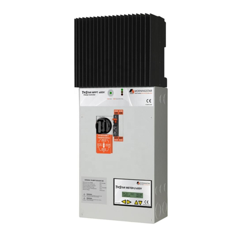
TS-M-2
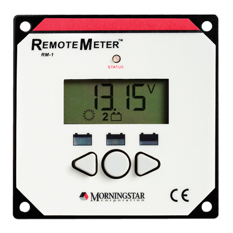
TS-RM-2
Ethernet MeterBus
Converter (EMC-1)
Mounting
Template
TriStar Charge
Controller TriStar Charge Controller
(with Optional Meter)
For use with 12 Vdc, 24 Vdc,
or 48 Vdc Systems
Wire Sizes and Torque Requirements:
• Circuit Breakers or fuses are required in the positive cable for Battery, Solar, DC Load, or Diversion Load connections.
• Solar connections require a PV Ground Fault Disconnect.
• A fuse is required in the positive cable for the Voltage Sense connections.
• Fuse or breaker sizing must be based on required wire ampacity.
• If using a fuse, do NOT insert the fuse in the fuse-holder until after all the other connections have been completed.
Fuses and Circuit Breakers:
IMPORTANT:
The TriStar Controller is designed to operate as a solar
charge controller, a load or lighting controller, OR a
diversion controller — one mode at a time and no
combined-mode operation.
Accessing the
wiring terminals:
To Access the Wiring Terminals:
1. Remove the 4 screws and star
washers from the faceplate.
2. Lift the faceplate away from
the base.
To Replace the Faceplate:
1. Align it with the base.
2. Replace the 4 screws and locking washers.
3. Hand tighten, careful not to over-tighten.
12
34
IMPORTANT:
Refer to Section 2.0, Installation, in the TriStar-PWM manual, for all details on installation requirements.
System design must comply with any applicable electrical code and regulations.
Relay Driver (RD-1)
MeterHub
MeterBus Communication
Hub (HUB-1)
TriStar-PWM-45
TriStar-PWM-60/M
Rated for 75°C Rated for 90°C
#8 AWG (10 mm2)#6 AWG (16 mm2)
Battery or Load Terminals
Torque
Maximum Length
Ground Terminal
#10 AWG (5 mm2)
#8 AWG (8 mm2)
MINIMUM WIRE SIZES AND TORQUE REQUIREMENTS
50 in-lbs. (5.56 Nm)
See Table 2.3-6a in the TriStar PWM Installation Manual for Maximum 1-way Wire Distance.
#6 AWG (16 mm2)#4 AWG (25 mm2)
2 See the Morningstar PV String Calculator at:
https://www.morningstarcorp.com/support/ CAUTION: This guide must be used with the full product manual that includes important information. Carefully
read the TriStar-PWM product manual for all specifications, safety, regulatory and warranty information, and for all
required instructions on installation procedures, configuration, and operation.
TS-45
Battery Voltage 12 Vdc, 24 Vdc, or 48 Vdc
Maximum Solar Input
Voltage2
12 V Nominal Array Voc
24 V Nominal Array Voc
48 V Nominal Array Voc
Maximum Current
(Solar or Load) 45 A
TS-60
60 A
TS-60M
Battery Operating Voltage 9-68 V
Battery Types Supported Flooded, Sealed
Maximum Current
(Diversion) 30 A 40 A
Load
+Bat –
Bat + Load –
RTS
V
Sens
32
TriStar Solar Controller Quick Start Guide
(+)
(–)
(+) (–)
Solar
Disconnect1
(PV GFP required per
NEC 690)
(See the Wiring and
Torque Table on page 4)
Photovoltaic (PV) Array
DC Load
Disconnect1
(See the Wiring and
Torque Table on page 4)
Power UP Sequence:
1. Connect Battery/Battery Bank.
2. Connect Solar or loads.
Power DOWN Sequence:
1. Disconnect Solar or loads.
2. Disconnect Battery/Battery Bank.
Mounting:
Minimum Clearance
Requirements:
CAUTION: Equipment Damage
Do not expose the TriStar CC to weather. Locate in a
dry, protected area to prevent equipment damage.
Ensure the minimum clearance requirements are
followed to provide adequate ventilation and prevent
the unit from overheating.
IMPORTANT: Example only. Actual wiring may vary. READ the TriStar
PWM Installation, Operations, and Maintenance Manual for mandatory
safety requirements. All configuration must comply with local and national
electric codes. Consult your local electric authority to ensure compliance.
See the Morningstar PV String Calculator at:
https://www.morningstarcorp.com/support/
Securing
hardware not
shown.
WARNING: Explosion Hazard
Never install the TriStar in an enclosure with
vented/flooded batteries. Battery fumes are
flammable and will corrode and destroy the TriStar
circuits. Ensure sufficient ventilation.
Battery
(+)
Battery
(—)
1Fuse or breaker sizing must be
based on required wire ampacity.
IF USING A FUSE, DO NOT INSERT THE
FUSE IN THE FUSE-HOLDER UNTIL
AFTER ALL THE OTHER CONNECTIONS
HAVE BEEN COMPLETED.
(+)
(–)
WARNING: Hazardous Voltage
Test between all terminals and ground before
touching.
Power or accessory terminals are NOT electrically
isolated from DC input and may be energized with
hazardous voltage.
(12-volt, 24-volt, or 48-volt)
WARNING:
Hazardous
Voltage
PV (+)
PV (–)
Load (+)
Load (–)
Battery
Disconnect1
(See the Wiring and
Torque Table on page 4)
Communications
Security Lighting
Industrial
Residential
DC Load(s)
The solar PV array can
produce open-circuit
voltages in excess of
125 Vdc when in
sunlight. Verify that
the solar input breaker
or disconnect has been
opened (disconnected)
before installing the
system wires.
1
2
1
2
12
Charge Control
Load Control
(+) (–)
1
2
Diversion Control
Disconnect1
(See the Wiring and
Torque Table on page 4)
Wind Hydro
(+) (–)
Disconnect1
(See the Wiring and
Torque Table on page 4)
3
4
Resistive Load
1
3
2
4
Primary
System
Ground
OR
Voltage
Sense (+)
RTS
(optional)
1/8"
(3 mm)
0.25" (6.4 mm) off wall
[0.25"]
Screw head height for #1 & #2 :
Do NOT exceed 0.50" (12.8 mm)
1 2
TS Meter (Back)
TS Meter
(Front)
IN
(TriStar)
OUT
(Meter)
Optional Accessories
TS-M-2
Remote Meter
(Back)
Remote
Meter
(Front)
TS-RM-2
RJ-11
Cable RJ-11
Cable
WARNING: Hazardous Voltage
Fuses, circuit breakers, and disconnect switches
should never open grounded system conductors.
Only GFDI devices are permitted to disconnect
grounded conductors.
IMPORTANT:
Ensure there is only 1 DC Negative-to-Ground Bond
in the entire system.
LEGEND
Negative (–)
Positive (+)
Ground
6"
(152.4 mm)
Fuse*
Array Voltage should
NEVER exceed the
maximum input voltage.
IMPORTANT:
WARNING: Risk of Fire
If no Remote Temperature Sensor (RTS) is connected,
use the TriStar-PWM within 10 feet (3 m) of the
batteries. Use of the RTS is strongly recommended.
Battery /
Battery Bank
Step 1: Choose mounting location
A) Locate the TriStar on a vertical surface that is protected
from direct sun, high temperatures, and water.
Step 2: Wiring accessibility and air flow clearance
A) Plan and confirm wire routing-access.
B) Verify that there is at least 6" of space above and below the
unit, and at least 3" (75 mm) around the heatsink.
Step 3: Drill holes
A) Place the TriStar template on the wall where the unit will
be mounted.
B) Mark and drill two (2) 1/8" (3.175 mm) holes in the top end
(slot) of each template keyhole.
C) Drive a #10 screw into each drill hole to 0.25" (or 6.4 mm)
from flush with the wall.
Step 4: Secure the controller
A) Place the controller circular keyhole areas over the wall screws,
and pull the unit down to lock the screws into the slots.
B) Use the two remaining screws to fasten the lower part of the
unit to the wall.
6"
(152.4 mm)
ON DIP
12345678
ON DIP
12345678
DIP Switch
Block
(enlarged)
(See Page 5 for
settings)
Voltage
Sense (—)
ON DIP
12345678
ON
OFF
Battery Charging/Load Control Mode (1)
Battery Voltage (2,3)
Mode Settings (4, 5, 6)
Battery Equalization/Diversion Mode (7)
Noise Reduction/Load or Lighting Control/
Battery Equalization (8)
Operational Settings:
IMPORTANT:
The DIP switches should be changed only when there is
no power to the controller. Turn off disconnect
switches and remove all power to the controller before
changing a DIP switch. A fault will be indicated if a
switch is changed while the controller is powered.
CAUTION: EQUIPMENT DAMAGE
The default position for the DIP switches is OFF.
Each switch position must be confirmed during
installation. Incorrect settings could cause damage
to the battery or other system components.
Battery Charging Load Control Mode
DIP Switch #1: Battery Charging/Load Control Mode Default Settings
Auto Select
DIP Switch #2 & 3: Battery Voltage
12 Volts
24 Volts 48 Volts
A = PWM 14.0 V
B = LVD 11.1 V
C = 6 hours after sunset
D = 13.8 V
DIP Switch #4, 5, & 6: Mode Settings
A = PWM 14.6 V
B = LVD 11.9 V
C = 4 hours after sunset,
2 hours before sunrise
D = 14.6 V
A = PWM 14.15 V
B = LVD 11.3 V
C = 8 hours after sunset
D = 14.0 V
A = PWM 14.8 V
B = LVD 12.1
C = 6 hours after sunset,
2 hours before sunrise
D = 14.8 V
A = PWM 14.35 V
B = LVD 11.5 V
C = 10 hours after sunset
D = 14.2 V
A = PWM 15.0 V
B = LVD 12.3 V
C = Dusk to Dawn
D = 15.0 V
A = PWM 14.4 V
B = LVD 11.7 V
C = 3 hours after sunset,
1 hour before sunrise
D = 14.4 V
A = PWM Custom*
B = LVD Custom*
C = Custom*
D = Custom*
A = Battery Equalization = Manual
B & C = NOT USED - MUST BE OFF
D = Diversion Control = OFF
DIP Switch #7: Battery Equalization or Diversion Control Mode
DIP Switch #8: Noise Reduction, Lighting/Load Control, or
Battery Equalization
DIP Function
(1)
(2,3)
(4, 5, 6)
(7)
(8)
Battery Charging Mode
Auto Voltage Select
Lowest Battery Charging Voltage (14.0 V)
Manual Equalization
Normal PWM Charging Mode
ON DIP
12345678
ON DIP
12345678
ON DIP
12345678
ON DIP
12345678
ON DIP
12345678
ON DIP
12345678
ON DIP
12345678
ON DIP
12345678
ON DIP
12345678
ON DIP
12345678
ON DIP
12345678
ON DIP
12345678
ON DIP
12345678
ON DIP
12345678
ON DIP
12345678
ON DIP
12345678
ON DIP
12345678
ON DIP
12345678
DIP Function
(1)
(2,3)
(4, 5, 6)
(7)
(8)
Load Control Mode
Select Battery Voltage 4
Low Voltage Disconnect 4
Not Used - MUST BE OFF
Load Control or Lighting Control 4
Mode B = Load Control or
Mode C = Lighting Control
ON DIP
12345678
ON DIP
12345678
ON DIP
12345678
3Select settings for DIP 2-8 that are specific
to the Installation. DIP 1 must be OFF.
4Select settings for DIP 2-6 & 8 that are specific to the
Installation. DIP 1 must be ON. DIP 7 MUST be OFF.
5Select settings for DIP 2-6 & 8 that are specific to the
Installation. DIP 1 must be ON. DIP 7 MUST be ON.
DIP Function
(1)
(2,3)
(4, 5, 6)
(7)
(8)
Battery Charging Mode
Select Battery Voltage 3
Standard Battery Charging Programs 3
Manual or Automatic Equalization 3
PWM Charging or Noise Reduction 3
Mode A = Battery Charging
DIP Function
(1)
(2,3)
(4, 5, 6)
(7)
(8)
Load Control Mode
Select Battery Voltage 5
Select Diversion Control Limits 5
Diversion Control Mode ON 5
Battery Equalization (Manual or Auto) 5
Mode D = Diversion Control
(*Requires Computer Connection. See TriStar
PWM Installation Manual for details.)
A = Battery Equalization = Auto
B & C = NOT USED – MUST BE OFF
D = Diversion Control = ON
A =Normal PWM Charging
B = Load Control
C = Load Control
D = Battery Equalization = Manual
A = Noise Reduction Mode
B = NOT USED—MUST BE OFF
C = Lighting Control
D = Battery Equalization = Auto 5
MS-003471 v2
A = Battery Charging
B = Load Control
C = Lighting Control
D = Diversion Control
Mode: Definitions:
PWM = Pulse Width Modulation
LVD = Low Voltage Disconnect
Settings by Mode:
General Transitions:
• Controller start-up G- Y– R (one cycle)
• Push-button transitions blink all 3 LEDs 2 times
• Battery service is required all 3 LEDs blinking until
service is reset
LED DISPLAY AND PUSH-BUTTON
FUNCTION:
Faults & Alarms:
• Short circuit - solar/load R/G - Y sequencing
• Overload - solar/load R/Y - Gsequencing
• Over-temperature R - Y sequencing
• High voltage disconnect R- Gsequencing
• Reverse polarity - battery No LEDs are illuminated
• Reverse polarity – solar No fault indication
• DIP switch fault R- Y - Gsequencing
• Self-test faults R -Y - Gsequencing
• Temperature probe (RTS) R/Y - G/Y sequencing
• Battery voltage sense R/Y - G/Y sequencing
Battery State-of-Charge (SOC) when battery is charging):
Battery Status:
Load Control:
LEDs
Push-Button
Battery Charging Status:
G
G/Y
Y
Y/R
R
13.3 V - PWM
13.0 to 13.3 V
12.65 to 13.0 V
12.0 to 12.65 V
26.6 V - PWM
26.0 to 26.6 V
25.3 to 26.0 V
24.0 to 12.3 V
53.2 V - PWM
52.0 to 53.2 V
50.56 to 52.0 V
48.0 to 50.56
12 V 24 V 48 V
0 to 12.0 V 0 to 24.0 V 0 to 48.0 V
Battery Charging Mode
(both solar and diversion):
LED Legend
• G = Green LED is illuminated
• Y = Yellow LED is illuminated
• R = Red LED is illuminated
• G/Y = Green and Yellow are both illuminated at the same time
• G/Y - R = Green & Yellow are both illuminated, then Red is illuminated alone
• Sequencing (faults) has the LED pattern repeating until the fault is cleared
• PUSH and RELEASE: Reset from an error
or fault.
• PUSH and RELEASE: Reset the battery
service indication if this has been activated with
the PC software. A new service period will be
started, and the flashing LEDs will stop blinking.
If the battery service is performed before the
LEDs begin blinking, the push-button must be
pushed at the time when the LEDs are blinking to
reset the service interval and stop the blinking.
• PUSH AND HOLD 5 SECONDS: Begin
battery equalization manually. This will begin
equalization in either the manual or automatic
equalization mode. The equalization will
automatically stop per the battery type selected.
• PUSH AND HOLD 5 SECONDS: Stop an
equalization that is in progress. This will be
effective in either the manual or automatic
mode. The equalization will be terminated.
PUSH-BUTTON FUNCTION:
• PUSH and RELEASE: Reset from an error
or fault.
• PUSH and HOLD 5 SECONDS: After a
low voltage disconnect (LVD) of the load, the
push-button can be used to reconnect the loads
again. The loads will remain on for 10 minutes,
and will then disconnect again. The push-button
can be used to override the LVD without limit.
Load and Lighting Control:
For Fault Recovery Instructions, see the TriStar PWM
Installation, Operation and Maintenance Manual.
G
G/Y
Y
Y/R
R Blinking
R
LVD +
LVD +
LVD +
LVD +
At LVD Threshhold
0.60 V
0.45 V
0.30 V
0.15 V
1.20 V
0.90 V
0.60 V
0.30 V
2.40 V
1.80 V
1.80 V
0.60 V
12 V 24 V 48 V
Below LVD
NOTE: The purpose of the LVD is to protect the
battery. Repeated overrides of an LVD can deeply
discharge the battery and may damage the battery.
MS-003471 v2
6
Absorption
Float
Start Equalization
Stop Equalization
G flash – every second
G flash – every 2 seconds
[G/ Y / R] x2 – G - G
[G/ Y/ R] x2 – R - R
Condition Indication
Equalize Gflash – 2 per second
• G= 80% to 95% SOC
• G/Y = 60% to 80% SOC
• Y = 35% to 60% SOC
• Y/R = 0% to 35% SOC
• R = battery is discharging

This manual suits for next models

2

Other Morningstar Controllers manuals

Morningstar SUNSAVER MPPT SS-MPPT-15L User manual

Morningstar

Morningstar SUNSAVER MPPT SS-MPPT-15L User manual

Morningstar ProStar MPPT Series User manual

Morningstar

Morningstar ProStar MPPT Series User manual

Morningstar ESSENTIAL Series User manual

Morningstar

Morningstar ESSENTIAL Series User manual

Morningstar ProStar PS-15 User manual

Morningstar

Morningstar ProStar PS-15 User manual

Morningstar ProStar PS-30M-PG User manual

Morningstar

Morningstar ProStar PS-30M-PG User manual

Morningstar SunSaver-10 User manual

Morningstar

Morningstar SunSaver-10 User manual

Morningstar TriStar TS-60 User manual

Morningstar

Morningstar TriStar TS-60 User manual

Morningstar PROSTAR-12 User manual

Morningstar

Morningstar PROSTAR-12 User manual

Morningstar GenStar GS-MPPT-60 User manual

Morningstar

Morningstar GenStar GS-MPPT-60 User manual

Morningstar ProStar MPPT TRAKSTAR PS-MPPT-15 User manual

Morningstar

Morningstar ProStar MPPT TRAKSTAR PS-MPPT-15 User manual

Morningstar SHS-6 User manual

Morningstar

Morningstar SHS-6 User manual

Morningstar EcoBoost MPPT EB-MPPT-20 User manual

Morningstar

Morningstar EcoBoost MPPT EB-MPPT-20 User manual

Morningstar EC-10 General instructions

Morningstar

Morningstar EC-10 General instructions

Morningstar TRISTAR TS-MPPT-60-600V-48-DB User manual

Morningstar

Morningstar TRISTAR TS-MPPT-60-600V-48-DB User manual

Morningstar ProStar-15 User manual

Morningstar

Morningstar ProStar-15 User manual

Morningstar Sunlight SL-10 User manual

Morningstar

Morningstar Sunlight SL-10 User manual

Morningstar TriStar Professional TS-60M User manual

Morningstar

Morningstar TriStar Professional TS-60M User manual

Morningstar ProStar PS-15M-48V User manual

Morningstar

Morningstar ProStar PS-15M-48V User manual

Morningstar SunSaver Duo SSD-25RM User manual

Morningstar

Morningstar SunSaver Duo SSD-25RM User manual

Morningstar SUNSAVER DUO User manual

Morningstar

Morningstar SUNSAVER DUO User manual

Morningstar REAKSTAR GenStar GS-MPPT-60M-200V User manual

Morningstar

Morningstar REAKSTAR GenStar GS-MPPT-60M-200V User manual

Morningstar SunSaver SS-6 User manual

Morningstar

Morningstar SunSaver SS-6 User manual

Morningstar SunGuard User manual

Morningstar

Morningstar SunGuard User manual

Morningstar SunSaver Series Guide

Morningstar

Morningstar SunSaver Series Guide

Popular Controllers manuals by other brands

FASTRON. MERIDIAN Series operating guide

FASTRON.

FASTRON. MERIDIAN Series operating guide

Vega VEGALOG 571 operating instructions

Vega

Vega VEGALOG 571 operating instructions

Mitsubishi MELSEC-F FX3U-4AD-PT-ADP user manual

Mitsubishi

Mitsubishi MELSEC-F FX3U-4AD-PT-ADP user manual

NXP Semiconductors ISP1183 user manual

NXP Semiconductors

NXP Semiconductors ISP1183 user manual

Titus TA1 Installation, operation and maintenance manual

Titus

Titus TA1 Installation, operation and maintenance manual

Protector AS-8000 operating instructions

Protector

Protector AS-8000 operating instructions

Onbon BX-Y1A user manual

Onbon

Onbon BX-Y1A user manual

D-Box HaptiSync Hub quick start guide

D-Box

D-Box HaptiSync Hub quick start guide

AC Tech SCF SERIES Installation and operation manual

AC Tech

AC Tech SCF SERIES Installation and operation manual

STIEBEL ELTRON SOM 6 plus Operation and installation

STIEBEL ELTRON

STIEBEL ELTRON SOM 6 plus Operation and installation

Philio PAN34 manual

Philio

Philio PAN34 manual

Shure AXT600 manual

Shure

Shure AXT600 manual

Aventics HF04 Assembly instructions

Aventics

Aventics HF04 Assembly instructions

Carel IR Series user manual

Carel

Carel IR Series user manual

Nice Elero ExitSafe 28 388.0001 manual

Nice

Nice Elero ExitSafe 28 388.0001 manual

Lumens VS-K20 user manual

Lumens

Lumens VS-K20 user manual

Omneon MediaDirector 2102B Quick reference guide

Omneon

Omneon MediaDirector 2102B Quick reference guide

Honeywell SW2 installation instructions

Honeywell

Honeywell SW2 installation instructions

manuals.online logo
manuals.online logoBrands
  • About & Mission
  • Contact us
  • Privacy Policy
  • Terms and Conditions

Copyright 2025 Manuals.Online. All Rights Reserved.