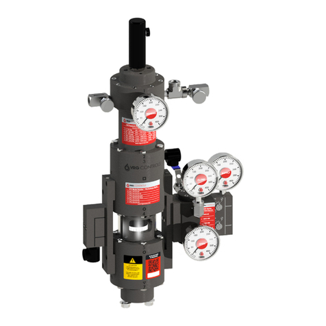
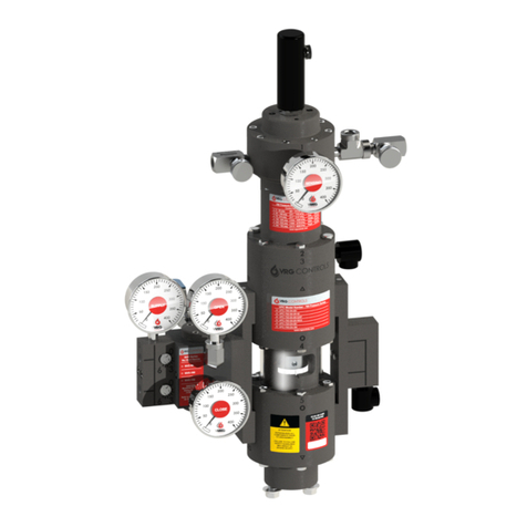
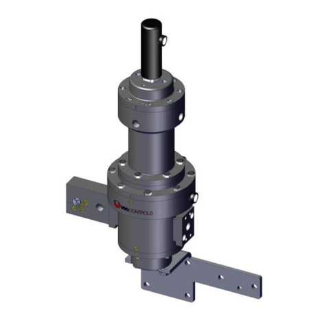
VRG Controls RCVC 3000 User manual

VRG CONTROLS LLC. 1 of 39 MAY 2021
RCVC 3000 - Red Circle Valve Controller
Installation, Operation, Maintenance Manual
VRG Controls LLC. 1 of 35 JANUARY 2019
Applicable Models:
ADDRESS:
TOLL FREE:
E-MAIL
WEBSITE:
STAY IN TOUCH!
VPC “SN” SERIES VALVE PILOT CONTROLLER
INSTRUCTION MANUAL
PATENT NO.:
US 9,400,060 B2
VPC PED ATEX Tag - Proof 3
Extreme-Tough
3.05” x 1.84”
OCTOBER 25, 2019
PATENT NO.:
US 9,400,060 B2
US 10,234,047 B2
RCVC 3000
INSTRUCTION MANUAL
Applicable Models:
This Instruction Manual applies to the following VRG - RCVC 3000. To conrm suitability for
additional models and/or componenents, please contact VRG Controls or view us online at
www.vrgcontrols.com
RCVC 3000
RCVC 3000 - Red Circle Valve Controller
Installation, Operation, Maintenance Manual

VRG CONTROLS LLC. 2 of 39 MAY 2021
RCVC 3000 - Red Circle Valve Controller
Installation, Operation, Maintenance Manual
DESCRIPTION PAGE
Scope of Manual 3
Technical Assistance 3
Features 3
Warnings 3
RCVC Specications 4
Navigation Wheel Tasks 5-9
USB Cable Setup Tasks 10-18
Figure 1: Wiring Diagram RCVC Analog Potentiometer Transmitter 19
Figure 2: Wiring Diagram RCVC Digital Potentiometer Transmitter 20
Figure 3: Wiring Diagram RCVC with Ballu Model BTL5 Linear Sensor 21
Figure 4: Wiring Diagram Remote RCVC Analog
Potentiometer Transmitter
22
Figure 5: Wiring Diagram Remote RCVC with Ballu Model BTL 7
Linear Sensor
23
Figure 6: Wiring Diagram Remote RCVC with Ballu Model BTL 5
Linear Sensor
24
Ballu Calibration 25-29
Figure 7: Spring to Open Ball Control Valve with RCVC, VMO &
Ballu TRM: XA-6015-AP01
30
Figure 8: Spring to Open Ball Control Valve with RCVC, VMO &
Ballu TRM: XA-6018-AP01
31
Figure 9: Spring to Open Ball Control Valve with RCVC, VMO &
Ballu TRM - Fail Closed
32
Figure 10: Spring to Open Glove Control Valve with RCVC, VMO &
Ballu TRM
33
Figure 11: Spring to Close Globe Control Valve with RCVC &
Ballu TRM
34
Figure 12: Spring to Close Glove Control Valve with RCVC, VMO &
Ballu TRM
35
Figure 13: Double Acting Ball Control Valve with RCVC, VMO &
Ballu TRM
36
Figure 14: Double Acting Ball Control Valve with RCVC, VMO &
Ballu TRM. Up to 250psig
37
Figure 15:Spring to Open Ball Control Valve with RCVC, VMO &
Ballu TRM, and Pressure Override
38
Table of Contents

VRG CONTROLS LLC. 3 of 39 MAY 2021
RCVC 3000 - Red Circle Valve Controller
Installation, Operation, Maintenance Manual
Scope of Manual
This Insturction Manual provides instructions for
operation, maintenance, adjustment and troubleshooting of
VRG Controls RCVC - Red Circle Valve Controller.
Conguration Methods
1. Navigation Wheel
2. Setup Application vis USB Setup Cable
Features
• Reverse Valve Action: Can easily switch between Direct
Acting and Reverse Acting.
• Three states of Edit Fail Modes: Lock Last, Fail Open
and Fail Close
• Three modes of Lockup Mode: Lock up Open, Lock up
Close or both.
• Split Range Conguration: Can set to any Range
• Dead Band Calibration for Open and Close: can be inde-
pendently set.
• Pulse Control: can adjust the Range when the Pulse is
activated
• Pulse Zone Timers: Adjust the length and duration of
pulse
• Fixed Command: Output for Pilot Override Applications
• Enable Anti-Surge Control: Set the Range for when the
Surge will Activate.
• Various Alarm Functions dependent on Failure State.
• Zero Out Solenoid Count: Can reset for new Solenoids
both Open and Close Count.
• Remote Command and Remote Override using 24VDC.
Technical Assistance
Should you have any questions, you may
contact your local VRG Controls sales representative or
VRG Controls technical assistance at:
VRG Controls
Attn: 1199 Flex Court
Lake Zurich, IL 60047
Toll-Free: 844-FLOW-VRG (844-356-9874)
Tel: + 1 847-778-6740
e-mail: [email protected]
websight: www.vrgcontrols.com
To facilitate requests for technical assistance, please have
the following information immediately available:
• Job number or serial number
• Fail states or messages
• Command signal Conguration
4ma to open or 20ma to open
• Interaction method
(navigation wheel or computer software)
Warning
Do NOT use a multimeter to check the feedback readings.
Do NOT use a multimeter to check feedback Retransmission
Signal. By connecting the negative lead to the feedback
(AI1) and the positive lead to 24 VDC, you will short out the
board. This will require a replacement board to x the issue.
Warning
The new RCVC app is not compatible with the old setup
les. To use the new RCVC you will need to load a new
setup le into the RCVC. The new setup les are compati-
ble with the old VRG Programming Application. Any RCVC
purchased after 3/1/2021 will have the new setup le already
installed in the RCVC.
Navigation Wheel USB Setup Cable

VRG CONTROLS LLC. 4 of 39 MAY 2021
RCVC 3000 - Red Circle Valve Controller
Installation, Operation, Maintenance Manual
Table 1.0 RCVC Specications
Power Supply
Power Supply 19-30 VDC
RCVC Module Current 50mA max
RCVC Total Assembly Rating 2A max
Onboard Fuse Limitron: FNQ-R-2 600VAC IR 200kA
Digital Outputs
Congurable Solenoids 3 Max
Voltage 24 VDC
Load Current (max) 1.0 Amps
Digital Inputs
No. Digital Inputs 2 (Congurable)
Voltage 24 VDC
Input Current 5.0 mAmps
Digital Outputs
No. Digital Outputs 3 (Open Sol, Close Sol, Auxiliary)
Voltage 24 VDC
Load Current (max) 250 mAmp
Analogue Inputs
No. Analogue Inputs 2 (Feedback, Command)
Input Type Current / Voltage
Voltage Input Range 1 - 5.0 VDC
Voltage Input Impedance 100 kOhms
Current Input Range 4 - 20 mA
Current Input Impedance 300 Ohms
Resolution 1 in 3600
Analogue Outputs
Output Type Current / Voltage
Voltage Output Range 4.0 - 20.0 ma / 0 - 3.0 VDC
Resolution 1 in 3600
Solenoid Ohms
AAA 58 - 65 Ohms
Asco 43 - 54 Ohms

VRG CONTROLS LLC. 5 of 39 MAY 2021
RCVC 3000 - Red Circle Valve Controller
Installation, Operation, Maintenance Manual
Navigation Wheel Common Tasks
1. Local Manual Operation
2. Command Signal Calibration
3. Feedback Signal Calibration
4. Retransmission Signal Calibration
5. Reverse Valve Action
6. Edit Fail Modes
7. Edit Lockup Mode
8. Split Range Conguration
9. Determine RCVC Version
10. Zero Out Solenoid Count
#1 Local Manual Operation
1. Apply 24 VDC Power Supply to RCVC
2. SHORT PUSH Navigation Wheel on RCVC Head
to enter MANUAL mode.
3. Rotate Navigation Wheel AWAY (CW) to increase
valve position percentage (%).
4. Rotate Navigation Wheel to NEUTRAL (center)
position to hold position.
5. Rotate Navigation Wheel Toward (CCW) to
decrease valve position percentage (%).
6. Rotate Navigation Wheel to NEUTRAL (center)
position to hold position.
7. Return Navigation Wheel to Neutral (Center)
Rotation Position. SHORT PUSH Navigation
Wheel on RCVC Head to exit Manual mode.
RCVC display Header should read AUTOMATIC.
#2 Command Signal Calibration
1. Apply 24 VDC Power Supply to RCVC
2. SHORT PUSH Navigation Wheel on RCVC Head
to enter MANUAL mode.
3. LONG PUSH Navigation Wheel on RCVC Head to
enter MENU mode.
4. Select “Application” and SHORT PUSH to enter.
5. Select “Physcial I/O” and SHORT PUSH to enter.
Navigation Wheel

VRG CONTROLS LLC. 6 of 39 MAY 2021
RCVC 3000 - Red Circle Valve Controller
Installation, Operation, Maintenance Manual
6. Select “Analogue Inputs” and SHORT PUSH to
enter.
7. Select “Command Signal” and SHORT PUSH to
enter.
8. Select “Calibration” and SHORT PUSH to enter.
9. Select “New Calibration” and SHORT PUSH to
enter.
10. Select “Minimum” and SHORT PUSH to enter.
11. Apply 4.0 mA Command Signal (MIN) and
SHORT PUSH to enter.
12. Select “Maximum” and SHORT PUSH to Enter.
13. Apply 20 mA Command Signal (MAX) and
SHORT PUSH to Enter.
14. Rotate Navigation Wheel to ESC Position to
reselect NEW CALIBRATION.
15. Rotate Navigation Wheel Toward (CCW) to
select SAVE CALIBRATION and SHORT PUSH
to enter.
16. Rotate Navigation Wheel to HOLD ESC Position
until menu stops at MANUAL on DISPLAY
HEADER.
17. Return Navigation Wheel to Neutral (Center)
Rotation Position. SHORT PUSH Navigation
Wheel on RCVC Head to exit MANUAL mode.
RCVC display Header should read AUTOMATIC.
#3 Feedback Signal Calibration
1. Apply 24 VDC Power Supply to RCVC
2. SHORT PUSH Navigation Wheel on RCVC Head
to enter Manual mode.
3. LONG PUSH Navigation Wheel on RCVC Head to
enter MENU mode.
4. Select “Application” and SHORT PUSH to enter.
5. Select “Physical I/O” and SHORT PUSH to enter.
6. Select “Analogue Inputs” and SHORT PUSH to
enter.
7. Select “Feedback” and SHORT PUSH to enter.
8. Select “Calibration” and SHORT PUSH to enter.
9. Select “New Calibration” and SHORT PUSH to
enter.
10. Select “Minimum” and SHORT PUSH to enter.
11. Use VMO or other method Stroke control valve
to VALVE OPEN (MIN) position and SHORT

VRG CONTROLS LLC. 7 of 39 MAY 2021
RCVC 3000 - Red Circle Valve Controller
Installation, Operation, Maintenance Manual
PUSH to enter.
12. Select “Maximum” and SHORT PUSH to enter.
13. Use VMO or other method Stroke control valve
to VALVE CLOSED (MAX) position and SHORT
PUSH to enter.
14. Rotate Navigation Wheel to ESC Position to
reselect NEW CALIBRATION.
15. Rotate Navigation Wheel Toward (CCW) to
select SAVE CALIBRATION and SHORT PUSH
to enter.
16. Rotate Navigation Wheel to HOLD ESC Position
until menu stops at MANUAL on DISPLAY
HEADER.
17. Return Navigation Wheel to Neutral (Center)
Rotation Position. SHORT PUSH Navigation
Wheel on RCVC Head to exit MANUAL mode.
RCVC display Header should read AUTOMATIC.
#4 Retransmission Signal Calibration
1. Apply 24 VDC Power Supply to RCVC
2. SHORT PUSH Navigation Wheel on RCVC Head
to enter Manual mode.
3. LONG PUSH Navigation Wheel on RCVC Head to
enter MENU mode.
4. Select “Application” and SHORT PUSH to enter.
5. Select “Physical I/O” and SHORT PUSH to enter.
6. Select “Analogue Outputs” and SHORT PUSH to
enter.
7. Select “Feedback” and SHORT PUSH to enter.
8. Select “Calibration” and SHORT PUSH to enter.
9. Select “New Calibration” and SHORT PUSH to
enter.
10. Select “Minimum” and SHORT PUSH to enter.
11. Use Navigation Wheel to set the Value so the
Output is equal to 4 ma, then SHORT PUSH to
save value.
12. Select “Maximum” and SHORT PUSH to enter.
13. Use Navigation Wheel to set the Value so the
Output is equal to 20 ma, then SHORT PUSH to
save value.
14. Rotate Navigation Wheel to ESC Position to
reselect NEW CALIBRATION.
15. Rotate Navigation Wheel Toward (CCW) to
select SAVE CALIBRATION and SHORT PUSH
to enter.
16. Rotate Navigation Wheel to HOLD ESC Position
until menu stops at MANUAL on DISPLAY
HEADER.
17. Return Navigation Wheel to Neutral (Center)
Rotation Position. SHORT PUSH Navigation
Wheel on RCVC Head to exit MANUAL mode.
RCVC display Header should read AUTOMATIC.
#5 Reverse Valve Action
1. Apply 24 VDC Power Supply to RCVC
2. Apply Command Signal to RCVC
3. SHORT PUSH Navigation Wheel on RCVC Head
to enter MANUAL mode.
4. LONG PUSH Navigation Wheel on RCVC Head to
enter MENU mode.
5. Select “Application” and SHORT PUSH to enter.
6. Select “Physical I/O” and SHORT PUSH to enter.
7. Select “Analogue Inputs” and SHORT PUSH to
enter.
8. Select “Command Signal” and SHORT PUSH to
enter.
9. Select “Sensor Range” and SHORT PUSH to
enter.
10. Select “Minimum” and SHORT PUSH to enter.
11. Use Navigation Wheel TOWARD (CCW) to ad
just value to 100% on Minimum. SHORT PUSH
to enter.
12. Select “Maximum” and SHORT PUSH to enter.
13. Use Navigation Wheel AWAY (CW) to adjust
value to 0.0% on Minimum. SHORT PUSH to
enter.
14. Rotate Navigation Wheel to HOLD ESC Position
until menu stops at MANUAL on DISPLAY
HEADER.
15. Return Navigation Wheel to Neutral (Center)
Rotation Position. SHORT PUSH Navigation
Wheel on RCVC Head to exit MANUAL mode.
RCVC display Header should read AUTOMATIC.

VRG CONTROLS LLC. 8 of 39 MAY 2021
RCVC 3000 - Red Circle Valve Controller
Installation, Operation, Maintenance Manual
#6 Edit Fail Modes
1. Apply 24 VDC Power Supply to RCVC
2. Apply Command Signal to RCVC
3. SHORT PUSH Navigation Wheel on RCVC Head
to enter MANUAL mode.
4. LONG PUSH Navigation Wheel on RCVC Head to
enter Menu mode.
5. Select “Application” and SHORT PUSH to enter.
6. Select “System Data” and SHORT PUSH to enter.
7. Select “System Inputs” and SHORT PUSH to
enter.
8. For FAIL OPEN Mode:
A. Select Line 8 - “Fault Open” and Click
Radio Button Current Status = “ACTIVE”
B. Select Line 9 - “Fault Close” and Click
Radio Button Current Status = “OFF”
9. For FAIL CLOSED Mode:
A. Select Line 8 - “Fault Open” and Click
Radio Button Current Status = “OFF”
B. Select Line 9 - “Fault Close” and Click
Radio Button Current Status = “ACTIVE”
10. For FAIL LAST Mode:
A. Select Line 8 - “Fault Open” and Click
Radio Button Current Status = “OFF”
B. Select Line 9 - “Fault Close” and Click
Radio Button Current Status = “OFF”
#7 Edit Lockup Mode
1. Apply 24 VDC Power Supply to RCVC
2. Apply Command Signal to RCVC
3. SHORT PUSH Navigation Wheel on RCVC Head
to enter MANUAL mode.
4. LONG PUSH Navigation Wheel on RCVC Head to
enter Menu mode.
5. Select “Application” and SHORT PUSH to enter.
6. Select “System Data” and SHORT PUSH to enter.
7. Select “System Inputs” and SHORT PUSH to
enter.
8. For LOCKUP OPEN Mode:
A. Select Line 11 - “Lockup Open” and Click
Radio Button Current Status = “ACTIVE”
B. Select Line 12 - “Lockup Close” and Click
Radio Button Current Status = “OFF”
9. For LOCKUP CLOSED Mode:
A. Select Line 11 - “Lockup Open” and Click
Radio Button Current Status = “OFF”
B. Select Line 12 - “Lockup Close” and Click
Radio Button Current Status = “ACTIVE”
1. Apply 24 VDC Power Supply to RCVC
2. Apply Command Signal to RCVC
3. SHORT PUSH Navigation Wheel on RCVC Head
to enter MANUAL mode.
4. LONG PUSH Navigation Wheel on RCVC Head to
enter MENU mode.
5. Select “Application” and SHORT PUSH to enter.
6. Select “System Data” and SHORT PUSH to enter.
7. Select “System Values” and SHORT PUSH to
enter.
8. Select Value 4 Open Limit and SHORT PUSH to
enter.
A. Set Open Limit to desired value when
Lockup needs to engage.
9. Select Value 5 Close Limit and SHORT PUSH to
enter.
A. Set Close Limit to desired value when
Lockup needs to engage.
Mode Line 8 -
Fault Open
Line 9 -
Fault Close
Fail OPEN
Loss 4-20 mA
ACTIVE OFF
Fail CLOSED
Loss 4-20 mA
OFF ACTIVE
LOCK LAST
Loss 4-20 mA
OFF OFF
Mode Line 11 -
LOCKUP OPEN
Line 12 -
LOCKUP CLOSED
LOCKUP OPEN ACTIVE OFF
LOCKUP CLOSED OFF ACTIVE

VRG CONTROLS LLC. 9 of 39 MAY 2021
RCVC 3000 - Red Circle Valve Controller
Installation, Operation, Maintenance Manual
#8 Split Range Conguration
1. Apply 24 VDC Power Supply to RCVC
2. Apply Command Signal to RCVC
3. SHORT PUSH Navigation Wheel on RCVC Head
to enter Manual mode.
4. LONG PUSH Navigation Wheel on RCVC Head to
enter MENU mode.
5. Select “Application” and SHORT PUSH to enter.
6. Select “Physical I/O” and SHORT PUSH to enter.
7. Select “Analogue Inputs” and SHORT PUSH to
enter.
8. Select “Command Signal” and SHORT PUSH to
enter.
9. Select “Calibration” and SHORT PUSH to enter.
10. Select “New Calibration” and SHORT PUSH to
enter.
11. Select “Minimum” and SHORT PUSH to enter.
12. Apply desired Command Signal value (## mA
Custom Value Here) for VALVE CLOSED
position (MIN) and SHORT PUSH to enter.
13. Select “Maximum” and SHORT PUSH to enter.
14. Apply desired Command Signal value (## mA
Custom Value Here) for VALVE OPEN position
(MAX) and SHORT PUSH to enter.
15. Rotate Navigation Wheel to ESC Position to
reselect NEW CALIBRATION.
16. Rotate Navigation Wheel Toward (CCW) to
select SAVE CALIBRATION and SHORT PUSH
to enter.
17. Rotate Navigation Wheel to HOLD ESC Position
until menu stops at MANUAL on DISPLAY
HEADER.
18. Return Navigation Wheel to Neutral (Center)
Rotation Position. SHORT PUSH Navigation
Wheel on RCVC Head to exit MANUAL mode.
RCVC display Header should read AUTOMATIC.
#9 Determine RCVC Version
1. Apply 24 VDC Power Supply to RCVC
2. SHORT PUSH Navigation Wheel on RCVC Head
to enter MANUAL mode.
3. LONG PUSH Navigation Wheel on RCVC Head to
enter MENU mode.
4. Scroll to SETTINGS and SHORT PUSH to select.
5. Scroll to ABOUT and SHORT PUSH to select.
6. SOFTWARE VERSION will read
A. “V3.13.3” for RCVC 1000
B. “V4.10.2” for RCVC 2000
C. “V4.24.6” for RCVC 3000
#10 Zero Out Solenoid Count
1. Apply 24 VDC Power Supply to RCVC
2. SHORT PUSH Navigation Wheel on RCVC Head
to enter MANUAL mode.
3. LONG PUSH Navigation Wheel on RCVC Head to
enter MENU mode.
4. Select “Application” and SHORT PUSH to enter.
5. Select “System Data” and SHORT PUSH to enter.
6. Scroll to “Open Sol. Count” and SHORT PUSH to
enter.
7. Select “Value” and SHORT PUSH to enter.
8. Use the Wheel to decrease the value to Zero and
SHORT PUSH to save.
9. Rotate Navigation Wheel to ESC position to exit
OPEN SOL COUNT.
10. Select “Close Sol Count” and SHORT PUSH to
enter.
11. Select “Value” and SHORT PUSH to enter.
12. Use the wheel to decrease the value to Zero and
SHORT PUSH to save.
13. Rotate Navigation Wheel to HOLD ESC Position
until menu stops at MANUAL on DISPLAY
HEADER.
14. Return Navigation Wheel to Neutral (Center)
Rotation Position. SHORT PUSH Navigation
Wheel on RCVC Head to exit MANUAL mode.
RCVC display Header should read AUTOMATIC.

VRG CONTROLS LLC. 10 of 39 MAY 2021
RCVC 3000 - Red Circle Valve Controller
Installation, Operation, Maintenance Manual
1 RCVC PROGRAMMING OVERVIEW
RCVC Programming Application is a windows based stand-
alone piece of software which is used to communicate with a
RCVC using a wired Modbus communication
protocol.
2 INSTALLATION
2.1 System Requirements
To ensure proper functionality of the RCVC programming ap-
plication a standard PC is required with at least the following
system resources:
• 1 gigahertz (GHz) or faster 32-bit (x86) or 64-bit (x64)
processor
• 1 gigabyte (GB) RAM (32-bit) or 2 GB RAM (64-bit)
• Screen resolution at least 1024 x 768 pixels
2.2 Operating Systems
The RCVC programming application will run on the following
operating systems:
• Windows 7 SPI (32 and 64 bit)
• Windows 8.1 (32 and 64 bit)
• Windows 10 (32 and 64 bit)
2.3 Hard Disk Space
The RCVC programming application requires approximately
20MB of hard disk space.
2.4 Installation
Extract the installation package to the local disk. Follow the
instructions on the setup wizard to complete the installation.
3 CONNECTION DETAILS
3.1 Modbus Modern
The USB-RS485 modbus modern recommended to be used
to communicate between RCVC programming application
and a RCVC is:
• DSD Tech SH-U10 USB to RS485 Converter with
CP2102 chip compatible with Windows 7, 8 and 10
3.2 Modbus Connection to a RCVC
To connect from a Modbus modem to a RCVC the positive
terminal of the modem must be connected to MOD+ of the
RCVC terminal, and the negative terminal of the modem
must be connected to MOD- of the RCVC terminal.
It must be noted that the specied baud rate and Modbus
address in the RCVC must match the set baud rate and
address in RCVC programming application in order for the
communication to be successful.
4 RCVC PROGRAMMING APPLICATION USER
GUIDE
4.1 Loading Page
When rst loading RCVC Programming Application the
following screen will be shown:
• File Structure - this area contains a list of all controllers
that have been connected to and can be loaded by dou-
ble clicking on a le. They are split into three sections:
• Online - the project and application of the controller
currently connect to
• Oine - a list of all projects and applications
(read-only)
• Standards - a list of saved standard applications
which can be re-used on projects to ensure similar
setups
• Application Details - detail;s of the application currently
loaded into the RCVC Programming Application
• RCVC Status - Indicates whether a controller is
connected and “Online” or not connected and “Oine”
• Current File - the program name of the application
loaded
• Main Interactive Area - the area where the application
is shown and can be interacted with. An application is
loaded when a le is double-clicked in the le structure
or when a RCVC is connected to

VRG CONTROLS LLC. 11 of 39 MAY 2021
RCVC 3000 - Red Circle Valve Controller
Installation, Operation, Maintenance Manual
4.2 Toolbars
•
•
• File/Save Application - use to save the currently loaded
application as a standalone text le. This le can then
be loaded as a standard on a dierent computer or sent
back to engineering for analysis (only enabled when a
le has been loaded)
• File/Import Standard - use to import a new standard
application into the Standard folder in the le structure.
• File/Exit - use to exit the application (NOTE: if current-
ly connected to a controller, exiting the application will
automatically disconnect from the controller)
• Device/Detect Device - use to determine if a controller
can be seen using the Modbus connection. If a control-
ler is found it will indicate on which COM port it was
found, otherwise it will indicate that it is unable to nd a
device (only enabled when not currently connected to
a contoller)
4.3 Screens
4.3.1 Home Tab
When RCVC programming application successfully
connects to a controller it downloads the application loaded
on the controller and loads a Home Page showing all
relevant operational data relevant to the application.
All the information on the home page is read-only and is
continuously polled so that it reects the current status of the
controller.
• Device/Connect Device - use to connect to a controller.
It will automatically download the application loaded on
the device and open up the corresponding application
details in the main interactive area (only enabled when
not currently connected to a controller)
• Device/Disconnect Device - use to disconnect from
controller (only enabled when connected to a controller)
• Modbus/Baud Rate - use to set the baud rate to match
the baud rate of the controller (only enabled when not
connected to a controller)
• Modbus/Address - use to set the required Modbus
address to match the controller address (only enabled
when not connected to a controller)
• Help/RCVC Manual - use to load this operation manual
• Help/About - use to load details for the current RCVC
programming application
Buttons are included on the home page which can be used
to calibrate the controller, and in the case of a diagnostic ap-
plication, operate the actuator and run diagnostic tests. Each
button with ask the user to conrm that the action should be
completed to prevent accidental operation of the controller.

VRG CONTROLS LLC. 12 of 39 MAY 2021
RCVC 3000 - Red Circle Valve Controller
Installation, Operation, Maintenance Manual
4.3.2 Setup Tab
The setup tab contains a number of sub-tabs which contain
all the settings within the application which can be changed
to aect the operation of the controller.
If the controller is online then the settings can be updated
and the change is immediately uploaded to the controller
(Note: a conrmation is required before a change is made to
ensure accidental changes are not made).
If viewing an oine application then the settings are
read-only as the oine application shows the status of that
controller when it was last connected as a record of each
controller.
If viewing a standard application then settings can be
updated as to change what settings are required for that
standard application. Changes are immediately saved when
they are made.

VRG CONTROLS LLC. 13 of 39 MAY 2021
RCVC 3000 - Red Circle Valve Controller
Installation, Operation, Maintenance Manual
4.3.3 Diagnostics Tab
EVENT LOGS
The Event Logs tab contains a list of all event logs record-
ed within the controller. It details the event that occurred,
the date it occurred, the duration of the event and the
number of times that the specic event has occurred.
The combo box at the top of the tab can be used to lter
down to specic events and the “from” and “to” dates can
be used to narrow down the time period of events.
4.4 Controller Report
The RCVC programming application contains the ability
to create a report detailing all the settings included in the
controller.
The column headers in the table can be clicked to sort
the events in either ascending or descending order to
further interrogate the data.
When connected to a controller a button will be shown
which can be clicked to update the Event Logs to show
the most current status of the controller.
By clicking the “Print Report to PDF” button in the top
right corner when either online or oine a report will be
generated for the loaded application.

VRG CONTROLS LLC. 14 of 39 MAY 2021
RCVC 3000 - Red Circle Valve Controller
Installation, Operation, Maintenance Manual
Open Programming Connection to RCVC
1. Ensure that the RCVC App is installed on the
c o m p u t e r a n d t h e U S B d r i v e r s h a v e b e e n
installed. To install USB drivers, connect the USB
to the computer and the drivers will install
automatically if there is an internet connection.
2. Open the RCVC App and ensure there is 24VDC
power to the RCVC.
3. Verify the USB is connected to the computer and
select DEVICE from the menu. Click on detect
device to ensure the RCVC App can
communicate to the RCVC. Once a connection is
established click on Device and select Connect
to device.
4. The program will automatically load the setup
le from the RCVC into the program. A window
will appear asking for a folder name and a le
name. For the folder name it is recommended
to put the station name. For the le name it is
recommended to put the job number, this way it
is easier to keep the les organized.
Eliminate Excessive COM PORTS
on Computer
When attempting to Open Programming Connection to
RCVC using the Setup Application operator may experience
diculty establishing a COM PORT. It may be necessary to
remove excessive COM PORTS on your WindowsTM
operating system.
1. Click Windows Button on Computer.
2. Type “Device Manager” and Select.
3. Click View, Show Hidden Devices.
4. Click Ports (COM & LPT)
5. Select any “Gray” COM Port and Click red “X” at
top of Window or DELETE.
6. Select uninstall when prompted “Do you want to
uninstall this connection?”
Read and Write Setup File from Controller
1. When connecting to the device the program will
automatically read the setup le. This can be
found under the Online tab on the left side of the
window. You can expand the online tab to see
the folder and le associated with the device.
2. To write a le to the device, right click on the le
name under the online section. Select Load
Standard File and then select the desired le
from the drop-down menu. Click OK to accept
the le and then select Yes to conrm you want to
overwrite the current le.
3. Once complete a message will appear saying
“Write setup le successful-clearing memory.”
Once the memory has been cleared a new
window will pop up letting you know this has
nished. Once complete, select device and
connect to device to reconnect.
Determining Setup le version in the
RCVC App
1. Open RCVC app software
2. Connect to the RCVC Via the USB connection
3. Once connected to the device Assign a project
and le name.
4. In the top information box the Application number
(VRG.4.24.4-2) will display the current setup le version.
VRG.4.24.4-1 for the old version and VRG.4.24.4-2 for the
new version.
Determining Setup le version On the RCVC
Controller
1. Short push the navigation wheel to go into manual mode.
2. Long push the navigation wheel to go into the menu.
3. Scroll down to Settings and short push to select.
4. Scroll to About and short push to select
5. Next to App Revision will be the setup le version num-
ber. VRG.4.24.4-1 for the old version and VRG.4.24.4-2 for
the new version.
New RCVC software setup le upgrade
1. Open RCVC app software
2. Connect to the RCVC Via the USB connection
3. Once connected to the device Assign a project and le
name.
4. Select the setup tab followed by the analog input tab.
5. Copy the calibration values for Feedback, Command and
Retransmission.

VRG CONTROLS LLC. 15 of 39 MAY 2021
RCVC 3000 - Red Circle Valve Controller
Installation, Operation, Maintenance Manual
7. Once all settings and calibrations have been restored
save the setup le (File -> Save Application)
a. To save the le as a standard le, for future RCVC
applications. Disconnect from the device and nd the project/
le under the oine section. Right click on the le and select
save as standard, this will allow you to select this le when
writing to a new device.
Command Signal Calibration
1. Open programming connection to RCVC and
connect to the device.
2. On the Home Tab, select Manual Calibration
under the calibration section.
3. In the calibration window select Analog Input from
the Type drop-down menu. Select command
Signal from the Signal drop-down menu.
4. Select start calibration, then send a 4ma signal to
the device and select the Set button for the
Minimum. Then send a 20ma signal to the device
and select the Set button for Maximum.
5. Once both values have been set Select the Stop
Calibration button to end calibration. Close out of
the window and select the Setup tab and the
Analog Input tab to verify that the values have
been updated under the COMMAND section.
Feedback Signal Calibration
1. Open programming connection to RCVC and
connect to the device.
2. On the home tab, under the CALIBRATION
section select Auto Calibration.
3. In the Calibration window select Start Auto
Calibration. The valve will automatically move and
save the values for full open and full close.
4. Once the calibration is complete there will be a
Finished message next to the Start Auto
Calibration button.
5. NOTE ** The Auto Calibration can ONLY be used
for the analog input feedback.
a. You can write the values down or you can put
them directly into a new setup le located in standards ->
VRG Defaults -> BV-LL (Ball Valve Lock Last)
6. Copy over any other changes from the old setup le: Dead
bands, pulse zone, solenoid count, lock up and fail modes.
Ensure that you new setup le matches the old one.
7. Next right click on the le name below the online section
and select load standard le. Select the correct le from the
drop-down menu (BV-LL) and click OK.
8. After the le nished writing to the device. Select device
-> connect to reconnect to the RCVC. The RCVC has now
been updated with the latest version of the setup le.
9. Verify that all calibrations are accurate and run a new
calibration if any need to be changed.
10. Once all settings and calibrations have been re-
stored save the setup le (File -> Save Application)
a. To save the le as a standard le, for future RCVC
applications. Disconnect from the device and nd the project/
le under the oine section. Right click on the le and select
save as standard, this will allow you to select this le when
writing to a new device.
Alternative Method for new Setup le
1. Open RCVC app software
2. Connect to the RCVC Via the USB connection
3. Once connected to the device Assign a project and le
name.
4. Right click on le name under the online section and
select load standard le and select the correct le from the
drop-down menu.
5. Once the le has ben loaded, select device -> connect to
device.
6. Once connected run through calibration procedures to
recalibrate the RCVC
a. Auto calibration to calibrate the Ballu (Westlock/
Soldo) to the RCVC
b. Manual calibration -> Analog Input-> Command
signal for 4-20ma command
c. Manual Calibration -> Analog output -> Feedback
for feedback to RTU (Gas Control)

VRG CONTROLS LLC. 16 of 39 MAY 2021
RCVC 3000 - Red Circle Valve Controller
Installation, Operation, Maintenance Manual
Manual Calibration of Feedback Signal
1. Open programming connection to RCVC and
connect to the device.
2. On the Home Tab, select Manual Calibration
under the calibration section.
3. In the calibration window select Analog Input from
the Type drop-down menu. Select Feedback from
the Signal drop-down menu.
4. Select start calibration, then move the valve to
the Full Open Position and accept the value in the
Minimum or Maximum depending of the value. If
the value is between 550-750 this is a 4ma signal
and it will be set to MINIMUM. If the value is
between 3200-3700 this is a 20ma signal and
should be set to MAXIMUM. Stroke the Valve to
the full close position and accept the value.
5. Once both values have been set Select the Stop
Calibration button to end calibration. Close out of
the window to nish the calibration.
Reverse Valve Action
1. Open programming connection to RCVC and
connect to the device.
2. Select the Setup Tab and under the COMMAND
section select the box next to the Minimum
Range. A window will appear that will contain the
current Minimum range valve (100%). Change this
value to 0% and click OK.
3. Select the box next to Maximum Range. A window
will appear that will contain the current Maximum
Range (0%). Change this value to 100% and click
OK.
4. This process will need to be repeated in the
RETRANSMISSION section as well.
5. MAKE SURE THAT COMMAND AND RETRANS
MISSION SIGNAL RANGE VALES ARE THE
SAME FOR MIN AND MAX
Edit Fail Modes
1. Open programming connection to RCVC and
connect to the device.
2. Click on the Setup Tab then select the Equipment
Tab.
3. Under the Fault actions section select the box
next to the Feedback fault Mode.
4. In the window that pops up, select the desired
fault mode in the drop-down menu. The fault
modes are OPEN, CLOSE, and STOP (lock last
position). Select OK to accept the current fault
mode.
5. Repeat the steps with the Command Fault Mode.
Edit Lockup Mode
1. Open programming connection to RCVC and
connect to the device.
2. Click on the Setup Tab then select the Equipment
Tab.
3. Under the Actuator Limits section, select the box
next to the Lock up Open or Lock up Close.
4. A window will pop up asking if you would like to
active “Hard seat Open/Close” Click OK to turn
lock up on.
5. To turn o simply select the box next to Lock Up
Open/Lock Up Close and select OK when
prompted by the window to turn Lock Up o.
Mode Sensor Range
MINIMUM
Sensor Range
MAXIMUM
Open on
Increasing /
Direct Acting
0.0% 100.0%
Close on
Increasing /
Reverse Acting
100.0% 0.0%
Click CLICK
RECORD MIN
CLICK
RECORD MAX
Mode Line 8 -
Fault Open
Line 9 -
Fault Close
Fail OPEN
Loss 4-20 mA
ACTIVE OFF
Fail CLOSED
Loss 4-20 mA
OFF ACTIVE
LOCK LAST
Loss 4-20 mA
OFF OFF

VRG CONTROLS LLC. 17 of 39 MAY 2021
RCVC 3000 - Red Circle Valve Controller
Installation, Operation, Maintenance Manual
Setting Open and Close Limits
1. Open programming connection to RCVC and
connect to the device.
2. Click on the Setup Tab then select the Equipment
Tab, the Limits will be found in the Actuator Limits
section.
3. To change the Open or Close limits, click on the
box next to the limit that needs to be changed. In
the pop-up window change to the desired value
and click OK.
4. The Open and Close limit is used to determine
when Lock up will occur. If the valve position is
below the Close limit or above the Open limit Lock
up will engage if it is turned on.
Split Range Conguration
1. Open programming connection to RCVC and
connect to the device.
2. On the Home Tab, select Manual Calibration
under the calibration section.
3. In the calibration window select Analog Input from
the Type drop-down menu. Select Command
Signal from the Signal drop-down menu.
4. Adjust Command Signal Input to desired value for
the valve CLOSE position and select Record
Minimum or Record Maximum depending on
value.
5. Adjust Command Signal Input to desired value for
the valve OPEN position and select Record
Minimum.
Dead Band Calibration
1. Open programming connection to RCVC and
connect to the device.
2. Click on the Setup Tab then select the Equipment
Tab the dead band will be in the Dead Zone
section.
3. In the Dead Zone section select the box next to
the value that needs to be changed. In the pop-up
window change the value to desired value.
a. NOTE: The static Dead Zone should
always be 0.1% greater than the moving
Dead Zone.
4. It is recommended to change both the open and
close dead bands, so they have the same value.
This can help reduce cycling issues when the
valve is in control.
Pulse Zone Control
1. Open programming connection to RCVC and
connect to the device.
2. Click on the Setup Tab then select the Equipment
Tab, the Opening and Closing Pulse Zone
sections will contain the value and the times
3. To change the Pulse zones, click on the box next
to the value and in the pop-up window change to
the new value. Click OK to accept the changes.
4. In this section the Pulse Zone times can be
changed as well to modify the duration of the
pulse.
a. Open/Close Max Move: Maximum time
Pulse will be active. VRG Value: 100ms
b. Open/Close Min Move: Minimum time
Pulse will be active. VRG Value: 30ms
c. Open/Close Max Pause: Maximum time
Pulse will be inactive. VRG Value: 150ms
d. Open/Close Min Pause: Minimum time
Pulse will be inactive. VRG Value: 150ms
Mode FULL Closed FULL Open
Open on
Increasing /
Direct Acting
6.0, 8.0, 10, 12
mA Typ.
20 mA
Close on
Increasing /
Reverse Acting
18, 16, 14, 12
mA Typ.
4.0 mA
Click CLICK
RECORD MIN
CLICK
RECORD MAX

VRG CONTROLS LLC. 18 of 39 MAY 2021
RCVC 3000 - Red Circle Valve Controller
Installation, Operation, Maintenance Manual
Fixed Command Output
1. Open programming connection to RCVC and
connect to the device.
2. Click on the Setup Tab then select the Digital I/O
Tab.
3. Under the Digital output 3 section, select the box
in line with Signal and select Command Output
from the drop-down menu in the pop-up window.
Then click OK to accept
4. Click on the Equipment Tab and under the
External Control section the Split Command value
will determine when the RCVC will relinquish
control.
5. Ex: For a 5mA signal on open, the increasing
system value entered needs to be 6.2%. This
means when command is at 6.2% or below the
auxiliary digital output will activate. Alternatively,
for closed, the increasing system value entered
for 5mA would be 93.8%.
Enable Anti-Surge Control
1. Open programming connection to RCVC and
connect to the device.
2. Click on the Setup Tab then select the Digital I/O
Tab.
3. Under the Digital output 3 section, select the box
in line with Signal and select Anti-Surge Valve
from the drop-down menu in the pop-up window.
Then click OK to accept.
4. Click on the Equipment tab and under the
External Control section the Anti-Surge Zone
value will determine when a surge will occur.
NOTE: the value represents the dierence in command
signal. IF the value is 10% then a command change greater
than 10% is needed to active the surge.
Remote Command Control
1. Open programming connection to RCVC and
connect to the device.
2. Click on the Setup Tab then select the Equipment
Tab, the Remote Command Control can be found
in the Actuator Control section.
3. Click the box in line with Remote Command
Control, a window will pop-up with a message
asking if you want to set Remote Command
Control to active. Click OK to make this change.
4. Land the wires to the Digital Input terminal inside
the RCVC. The valve can be controlled using
24VDC. This can only open and close the valve, it
is not recommended for control.
#18 System Inputs Description
1. 4-20ma CMD Ctrl - 4-20ma command control
option
2. Remote CMD Ctrl - Separate command signal
option (will override 4-20 signal)
3. Remote Override - Remote control to override fail
or fault. Open or Close only.
4. Remote Open - Set to active to use open
command in Digital Inputs (will override 4-20ma
signal)
5. Remote Close - Set to active to use close
command in Digital Inputs (will override 4-20ma
signal)
6. Manual Enable - Allows manual mode to be
enabled or disabled (only automatic mode if
disabled)
7. Manual Fast Pos - Removes pulse function when
using the manual wheel to control valve.
8. Fault Open - Set failure mode to open the valve
on loss of Command or Feedback.
9. Fault Close - Set failure mode to open the valve
on loss of Command or Feedback.
10. Fault Fast Pos - Disables pulse setting when a
failure occurs.
11. Lock Up Open - Enables lock up on the open
side of the valve.
12. Lock Up Close - Enables lock up on the close
side of the valve.
13. Lock Up Fast Pos - Disables Pulse setting when
Lock Up engages.
14. Fail on Feedback Fault - Enters failure mode if a
Feedback fault occurs.
15. Fail on CMD Fault - Enter failure mdoe if a
Command Fault occurs.
16. Auto Mode Switch - Switches to Automatic Mode.
17. Man Mode Timer - Enables a time limit for
Manual mode, switches back to Auto mode after
time ends.

VRG CONTROLS LLC. 19 of 39 MAY 2021
RCVC 3000 - Red Circle Valve Controller
Installation, Operation, Maintenance Manual
Figure 1: Wiring Diagram RCVC Analog Potentiometer Transmitter
TERMINAL BLOCK
INCOMING
FUSE 2AMPS
B
NOTES:
1. SET OPEN/CLOSE ON INCREASING SIGNAL.
APPLICATION/PHYSICAL I/O/ANALOGUE INPUTS/SENSOR RANGE
0.5=100% MAX,0 MIN.; CI=100%MIN,0 MAX.
2. DIGITAL INPUT 1 AND 2 ARE SETUP FOR 24 VDC REMOTE
OVERRIDE - ENABLE REMOTE COMMAND AND REMOTE
OVERRIDE IN SYSTEM INPUTS.
OPEN MOVING - 0.4
OPEN STATIC - 0.5
CLOSE MOVING - 0.4
CLOSE STATIC - 0.5
2. SET DEAD BANDS APPLICATION:
VRG Red Circle
Controller
MODBAS TO PC
I/O SET UP / SYSTEM DATA/ SYSTEM VALUES
REV
DESCRIPTION
DATE
BY
A
FIRST RELEASE
7/31/2015
VI
B
ADDED
"+"
to
DI1&DI2,
ADDED
"24VDC CLOSE "
to
DI1 & "24VDC OPEN "
to
DI2
12/4/2019
VI
D
C
B
A
A
B
C
D
1
2
3
4
5
6
7
8
8
7
6
5
4
3
2
1
WD-0210
RCVC-2000/3000 WIRING MAP; Digital TRM, Analog Input
12/4/2019
A
REV:
P/N:
TITLE:
REV DATE:

VRG CONTROLS LLC. 20 of 39 MAY 2021
RCVC 3000 - Red Circle Valve Controller
Installation, Operation, Maintenance Manual
Figure 2: Wiring Diagram RCVC Digital Potentiometer Transmitter
This manual suits for next models
1
Other VRG Controls Controllers manuals
Popular Controllers manuals by other brands

Analog Technologies
Analog Technologies ATLS100MA103 quick start guide

Franklin Electric
Franklin Electric SubDrive75 installation manual

ProMinent
ProMinent DCM3 Series quick start guide

Physik Instrumente
Physik Instrumente E-625.CR user manual

YASKAWA
YASKAWA A1000 Series Technical manual

Maxim
Maxim 53391 installation instructions