manuals.online logo
Brands
  1. Home
  2. •
  3. Brands
  4. •
  5. Morningstar
  6. •
  7. Controllers
  8. •
  9. Morningstar ESSENTIAL Series User manual

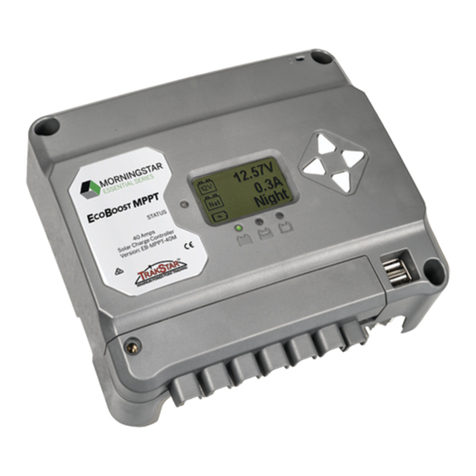
Morningstar ESSENTIAL Series User manual

Quick Start Guide
14
Warning: Shock Hazard
Test between all terminals and
ground before touching.
Power or accessory terminals are
NOT electrically isolated from DC
input and may be energized with
hazardous solar voltage.
Switch 1: Load/Lighting Switches 2 & 3: System Voltage
Specifications:
Switches 4, 5, & 6: Battery Type Selection
Switch 7: Battery Equalization Switch 8: Not Used
Operational Configuration:
Lighting
Normal
EB-MPPT-20,
EB-MPPT-20M
Nominal Battery Voltage 12/24 V
Max. PV Open-Circuit Voltage 120 V
Nominal Maximum Input Power 300 / 600 W
Maximum Battery Charging Current 20 A
Rated Load Current 20 A
EB-MPPT-30,
EB-MPPT-30M
12/24 V
120 V
400 / 800 W
30 A
30 A
© 2023 Morningstar Corporation. All Rights Reserved.
In the box:
Mounting
Template
Tools Required:
— #2 Philips Screwdriver
— 3/16 (5 mm) & 3/32" (2.5 mm) Flathead Screwdriver
— Drill with a 1/8" (3 mm) bit
— Multimeter
*A Menu Map is also included
with metered versions, but is not
shown in this guide.
Safety Information:
Warning: Shock Hazard
The EcoBoost MPPT controller must be installed by a
qualified technician in accordance with the electrical
regulations of the country of installation.
Warning: Shock Hazard
This unit is not provided with a GFDI device. This
charge controller must be used with an external GFDI
device as required by the Article 690 of the National
Electrical Code for the installation location.
IMPORTANT:
READ the EcoBoost Installation,
Operation and Maintenance Manual for safety and
regulatory information, instructions on configuration
and operation, and warranty information.
Ferrite Chokes
(x3)
PV Ground Fault Protection
(GFPD-150V and GFPD-600V)
Remote Temperature
Sensor (RTS)
Scan QR Code to go
directly to the EcoBoost
MPPT Installation
Manual and warranty
information online.
Contact Information:
Technical Support: Support.morningstarcorp.com
Phone: 1-215-321-4457
AUTO 12 V
24 V
Manual EQ Auto EQ
EcoBoost MPPT ™
Charge Controller
(with Meter)
N/ADefault
System Voltage Switch 2
Auto OFF
12 OFF
Switch 3
OFF
ON
24 ON OFF
Mode Switch 1
Normal OFF
Lighting ON
Mode Switch 7
Manual Equalization OFF
Auto-Equalization ON
Warranty Registration: https://www.morningstarcorp.com/product-registration/
Float Cancel Voltage 12.30 Volts*
Float Exit Time-Out 30 minutes
Absorption Extension Time Absorption Time +30 minutes
Absorption Extension Voltage 12.50 Volts*
Shared Settings Set Point Shared Settings Set Point
Temperature Compensation Co-Efficient –30 millivolts / °C / 12 Volts*
Equalize Time-Out Equalize Time +60 minutes
DIP Switch Setting
Battery Type
Absorption
Stage
(Volts)*
Float Stage
(Volts)*
Equalize
Stage
(Volts)*
Absorption
Time
(Minutes)
Equalize
Time
(Minutes)
Equalize
Timeout
(Minutes)
Equalize
Interval
(days)
4 5 6
OFF OFF OFF 1 – Sealed** 14.00 13.50 --- 150 --- --- ---
OFF OFF ON 2 – Sealed** 14.15 13.50 14.40 150 60 120 28
OFF ON OFF 3 – Sealed** 14.30 13.50 14.60 150 60 120 28
OFF ON ON 4 – AGM/Flooded 14.40 13.50 15.10 180 120 180 28
ON OFF OFF 5 – Flooded 14.60 13.50 15.30 180 120 180 28
ON OFF ON 6 – Flooded 14.70 13.50 15.40 180 180 240 28
ON ON OFF 7 – L-16 15.40 13.40 16.00 180 180 240 14
ON ON ON 8 – Custom*** Custom Custom Custom Custom Custom Custom Custom
* Multiply the voltage by 2 for 24-volt systems.
** “Sealed” battery types include Gel and AGM Batteries
*** Custom settings can be used for lead-acid batteries.
NOTE: The EcoBoost settings are not
compatible with Lithium-ion batteries.
MS-004019 Rev. 1
• EB-MPPT-20,
• EB-MPPT-30
• EB-MPPT-40
For 12- or 24-volt Systems
EB-MPPT-40,
EB-MPPT-40M
12/24 V
120 V
560 / 1,120 W
40 A
30 A
#8 Self-tapping
Mounting Screws
(x4)
Optional
Accessories:
• EB-MPPT-20M
• EB-MPPT-30M
• EB-MPPT-40M
1 2 3 4 5 6 7 8
DIP
ON
1 2 3 4 5 6 7 8
DIP
ON
1 2 3 4 5 6 7 8
DIP
ON
1 2 3 4 5 6 7 8
DIP
ON
1 2 3 4 5 6 7 8
DIP
ON
1 – Sealed ** 2 – Sealed **
1 2 3 4 5 6 7 8
DIP
ON
3 – Sealed **
1 2 3 4 5 6 7 8
DIP
ON
4 – AGM /
Flooded
1 2 3 4 5 6 7 8
DIP
ON
5 – Flooded
1 2 3 4 5 6 7 8
DIP
ON
6 – Flooded
1 2 3 4 5 6 7 8
DIP
ON
7 – L-16
1 2 3 4 5 6 7 8
DIP
ON
Custom***
1 2 3 4 5 6 7 8
DIP
ON
1 2 3 4 5 6 7 8
DIP
ON
1 2 3 4 5 6 7 8
DIP
ON
1 2 3 4 5 6 7 8
DIP
ON
1 2 3 4 5 6 7 8
DIP
ON
1 2 3 4 5 6 7 8
DIP
ON
Models:
EcoBoost MPPT ™
Charge Controller
(without Meter)
OR
Worlds Leading Solar Controllers & Inverters
NOTE: Regardless of DIP 7 setting, manual
EQ can be initiated using the on-board meter
command, Start Equalize. For non-meter
versions, DIP 7 only enables or disables auto
equalization; manual EQ is not available.
To select pre-configured settings (all models):
• Configure DIP Switches 4, 5, and 6 to one of the
pre-configured selections shown below.
See the EcoBoost Installation, Operations, and Maintenance Manual for additional information/guidance.
To select customized settings (metered versions only):
• Set DIP Switches 4, 5, and 6 to Custom and use the
interface on the meter to configure the settings.
NOTE: The EcoBoost MPPT (metered models only) can be programmed to accommodate a wide range of charging parameters.
Consult the battery manufacturer for optimal battery charging settings.
EIC 62109-1
EN 62109-1
32
EcoBoost™ Solar Charge Controller Quick Start Guide
6" (15 cm) MAXIMUM Distance
from Battery (+) Terminal
(+)
(–) (+)
(–)
120 Voc Maximum
(+) (–)
Solar Disconnect1
(PV GFP required per NEC 690)
Photovoltaic (PV) Array
Battery /
Battery Bank
Battery Disconnect1
Fuse1
Primary Ground Electrode
Conductor
(System Ground)
DIP Switch Block
(enlargement)
(See Page 4 for settings)
Remote Temperature
Sensor Conductor
Chassis Ground
(Connects to
the M4 screw
on the heatsink
on the back)
DC-to-Ground
Bond
Ferrite Choke2
Ferrite
Choke2
Mounting:
#2 Philips
Screwdriver
1/8"
(3mm)
1. Remove the terminal cover on the charge controller.
2. Use the Mounting Template to pre-drill the mounting holes.
3. Drill holes 1, 2, 3, & 4.
4. Place a screw on which to hang the controller in holes 1 & 2.
5. Back the screw out to 0.150" or 3.8 mm.
6. Place the controller onto the hanging screws.
Secure the controller in place with the other 2 screws (3 & 4).
34
12
Mounting Template
0.150" (3.8 mm) off back plane
[3.8 mm]
Screw Head Height for #1 & #2 :
Do NOT exceed 0.250" (6.4 mm)
IMPORTANT: Example only. Actual wiring may vary. READ
the EcoBoost MPPT Installation, Operations, and Maintenance
Manual for mandatory safety requirements. All configurations
must comply with local and national electric codes. Consult your
local electric authority to ensure compliance.
This illustration represents a typical off-grid installation. For use
with an inverter, refer to the inverter’s installation manual for
additional information.
IMPORTANT:
Ensure there is only 1 DC Negative-to-
Ground Bond in the entire system.
Battery
(–)
See the Morningstar PV String Calculator at:
http://string-calculator.morningstarcorp.com/
Component
Power Terminals
Wire Size
2.5 - 16 mm2/
#14 - 2 AWG
Tool Required
3/16"(5 mm)
Flathead Screwdriver
Cover Screws --- #2 Philips Screwdriver
Wiring and Torque Requirements
Torque (Max)
35 in-lbs.
(3.95 Nm)
5 in-lbs.
(0.56 Nm)
Remote Temperature
Sensor (RTS) (included) 3/32" (2.5 mm)
Flathead Screwdriver
5 in-lbs.
(0.56 Nm)
Securing
hardware
not shown.
Battery
(+)
Negative (–)
Positive (+)
Ground
LEGEND
1 2 3 4 5 6 7 8
DIP
ON
(+)
(–)
Morningstar EcoBoost MPPT
Controller Mounting Template
12-volt or 24-volt
USB Ports (x2)2
Devices to be charged
by the USB Ports2
Power UP Sequence:
1. Connect Battery/Battery Bank.
2. Connect Solar.
Power DOWN Sequence:
1. Disconnect Solar.
2. Disconnect Battery/Battery Bank.
2Note:
Ferrite Chokes ensure compliance with
electromagnetic emissions standards.
See Section 4.8, Auxiliary USB Charging
for additional information.
Ferrite Choke2
Minimum
Clearance
Requirements
Caution:
Equipment Damage
Do not expose the EcoBoost to
weather. Locate in a dry, protected
area to prevent equipment damage.
Ensure the minimum clearance
requirements are followed to provide
adequate ventilation and prevent the
unit from overheating.
6" (15 cm)
2" (5 cm)
6" (15 cm)
2" (5 cm)
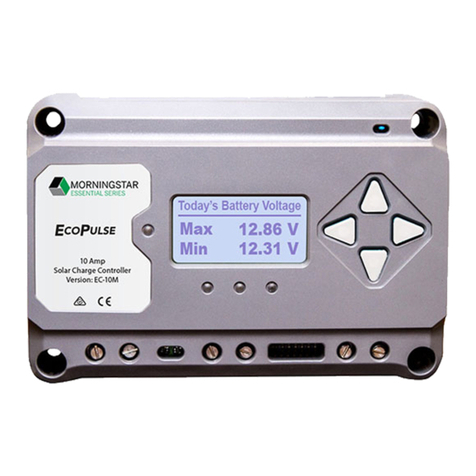
Today’s Battery Voltage
Max 12.95 V
Min 12.49 V
WARNING: Explosion Hazard
Never install the EcoBoost in an enclosure with vented/
flooded batteries. Battery fumes are flammable and will
corrode and destroy the EcoBoost circuits. Ensure
sufficient ventilation.
DC Load(s)
Status LED3LCD Meter Display
(Metered versions only)
SOC
LEDs3
3Note:
See the EcoBoost MPPT Installation,
Operations, and Maintenance Manual
for additional information on LED
indications.
1 WARNING: Risk of Fire
All over-current protection devices and wiring must
be sized properly, in accordance with US National
Electric Code (NEC) or the country of installation’s
local regulations. Fuses or circuit breakers must be
sized according to wire ampacity.

This manual suits for next models

6

Other Morningstar Controllers manuals

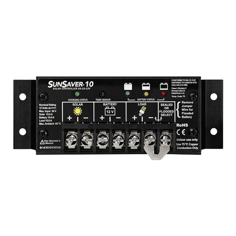
Morningstar SunSaver Duo SSD-25RM User manual

Morningstar

Morningstar SunSaver Duo SSD-25RM User manual

Morningstar TriStar TS-60M User manual

Morningstar

Morningstar TriStar TS-60M User manual

Morningstar SHS-6 User manual

Morningstar

Morningstar SHS-6 User manual

Morningstar TRISTAR TS-MPPT-60-600V-48-DB User manual

Morningstar

Morningstar TRISTAR TS-MPPT-60-600V-48-DB User manual

Morningstar ProStar MPPT TRAKSTAR PS-MPPT-15 User manual

Morningstar

Morningstar ProStar MPPT TRAKSTAR PS-MPPT-15 User manual

Morningstar MC6 MkII User manual

Morningstar

Morningstar MC6 MkII User manual

Morningstar SUNSAVER SS-10-12V User manual

Morningstar

Morningstar SUNSAVER SS-10-12V User manual

Morningstar SunLight-10 User manual

Morningstar

Morningstar SunLight-10 User manual

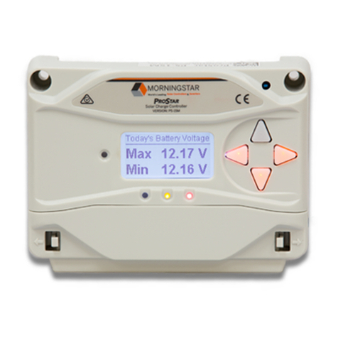
Morningstar ProStar PS-15 User manual

Morningstar

Morningstar ProStar PS-15 User manual

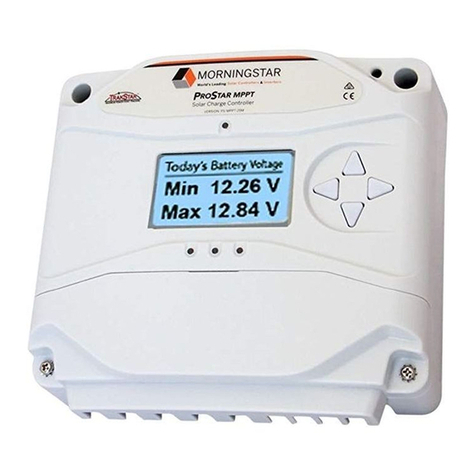
Morningstar ProStar MPPT Series User manual

Morningstar

Morningstar ProStar MPPT Series User manual

Morningstar SUNSAVER DUO User manual

Morningstar

Morningstar SUNSAVER DUO User manual

Morningstar PROSTAR-12 User manual

Morningstar

Morningstar PROSTAR-12 User manual

Morningstar SUNSAVER MPPT Series User manual

Morningstar

Morningstar SUNSAVER MPPT Series User manual

Morningstar ProStar-15 User manual

Morningstar

Morningstar ProStar-15 User manual

Morningstar SunSaver MPPT Meter Map User manual

Morningstar

Morningstar SunSaver MPPT Meter Map User manual

Morningstar ProStar MPPT Series User manual

Morningstar

Morningstar ProStar MPPT Series User manual

Morningstar SUNSAVER DUO User manual

Morningstar

Morningstar SUNSAVER DUO User manual

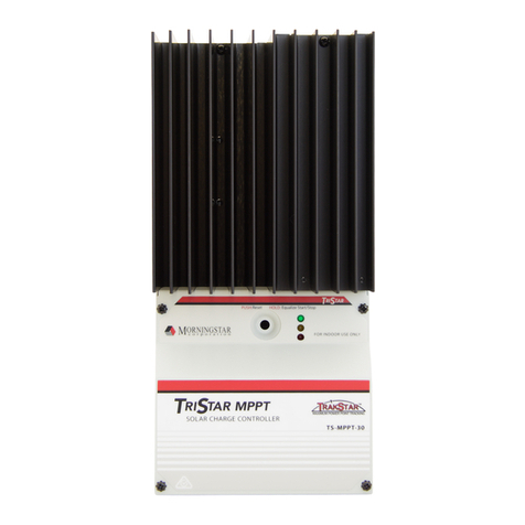
Morningstar TriStar TS-MPPT-30 User manual

Morningstar

Morningstar TriStar TS-MPPT-30 User manual

Morningstar SUNSAVER MPPT SS-MPPT-15L User manual

Morningstar

Morningstar SUNSAVER MPPT SS-MPPT-15L User manual

Morningstar SunSaver SS-6 User manual

Morningstar

Morningstar SunSaver SS-6 User manual

Morningstar SunSaver-10 User manual

Morningstar

Morningstar SunSaver-10 User manual

Morningstar SUNSAVER MPPT SS-MPPT-15L User manual

Morningstar

Morningstar SUNSAVER MPPT SS-MPPT-15L User manual

Morningstar ProStar PS-15M-48V User manual

Morningstar

Morningstar ProStar PS-15M-48V User manual

Morningstar REAKSTAR GenStar GS-MPPT-60M-200V User manual

Morningstar

Morningstar REAKSTAR GenStar GS-MPPT-60M-200V User manual

Popular Controllers manuals by other brands

Grundfos UPZCP-3 Installation and operating instructions

Grundfos

Grundfos UPZCP-3 Installation and operating instructions

iNels JA2-02B Manual instruction

iNels

iNels JA2-02B Manual instruction

ABB ACS150 series user manual

ABB

ABB ACS150 series user manual

ZTW Spider Series Manual instruction

ZTW

ZTW Spider Series Manual instruction

Briggs & Stratton GC1031 Operation instructions

Briggs & Stratton

Briggs & Stratton GC1031 Operation instructions

Anaheim Automation PCL511 user guide

Anaheim Automation

Anaheim Automation PCL511 user guide

Embedded Systems PT1000 Quick start up guide

Embedded Systems

Embedded Systems PT1000 Quick start up guide

Eaton xComfort CDAE-01/01 Assembly instructions

Eaton

Eaton xComfort CDAE-01/01 Assembly instructions

Burkert 1094 Series operating instructions

Burkert

Burkert 1094 Series operating instructions

Boehringer 7700 Series Technical Manual and Operating and Maintenance Instructions

Boehringer

Boehringer 7700 Series Technical Manual and Operating and Maintenance Instructions

Yamatake SDC10 Series manual

Yamatake

Yamatake SDC10 Series manual

Rain AMICO PRO instructions

Rain

Rain AMICO PRO instructions

Pilz PNOZ m EF SafetyNET operating manual

Pilz

Pilz PNOZ m EF SafetyNET operating manual

Carrier i-Vu Open Link Installation and startup guide

Carrier

Carrier i-Vu Open Link Installation and startup guide

Srne HM-CU Series user manual

Srne

Srne HM-CU Series user manual

Auber Instruments EZboil DSPR120 instruction manual

Auber Instruments

Auber Instruments EZboil DSPR120 instruction manual

Hamworthy Merley Installation, commissioning and operating instructions

Hamworthy

Hamworthy Merley Installation, commissioning and operating instructions

3Ware 7000-2 - Escalade RAID Controller Features

3Ware

3Ware 7000-2 - Escalade RAID Controller Features

manuals.online logo
manuals.online logoBrands
  • About & Mission
  • Contact us
  • Privacy Policy
  • Terms and Conditions

Copyright 2025 Manuals.Online. All Rights Reserved.