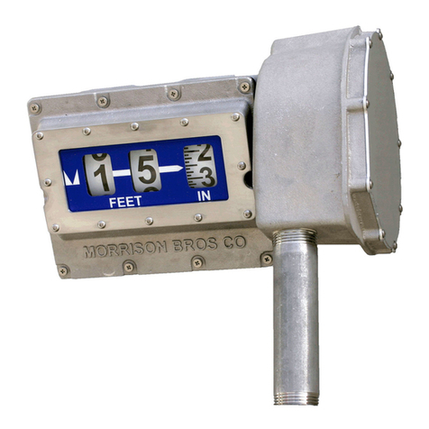
Morrison Bros. co. 918DP Manual

1
Morrison Bros. Co. - Dubuque, IA - 800-553-4840
918DP-0120 PPEVR
rev. 09-30-15
!
!
The 918DP Clock Gauge is designed to measure liquid volume in an aboveground storage tank. The gauge
mounts on top of the tank and is activated by a float connected to a cable. The 918DP contains two normally
open switches to connect to an alarm device that can provide an audible alarm at two desired tank levels that are
set during installation.
Failure to follow any or all of the warnings and instructions in this document could result in a hazardous
liquid spill, which could result in property damage, environmental contamination, fire, explosion, serious
injury or death.
NOTE: The most accurate method to calibrate the tank is with fluid in it. This will take into account variables
associated with the float position, the mechanism, and the fluid density. To calibrate a low alarm setting, the
tank fluid level must be several inches lower than the desired alarm level setting.
Electrical Switch Ratings
10 watt resistive load, 127VAC-354mA max / 180VDC-500mAmax (Ratings for resistive loads only.)
*Do not use for inductive loads.
Gauge Installation & Calibration
WARNINGS
• Fire Hazard – Death or serious injury could result from spilled liquids.
• You must be trained to install or maintain this gauge. Stop now if you have not been trained.
• Any modification to this gauge other than those stated in these installation instructions will void the
product warranty.
• This device is intended to be used as an auxiliary warning to the operator of a possible overfill situation
and should not be the only system in place to prevent a tank from overfilling. It is the sole responsibility
of the operator to continuously prevent any spillage regardless of the situation or status of the gauge.
• Install in accordance with all applicable local, state, and federal laws.
• For your safety, it is important to follow local, state, federal and/or OSHArules that apply to work-
ing inside, above, or around the storage tank and piping area. Use all personal protective equipment
required for working in the specific environment.
• Tanks could be under pressure. Vapors could be expelled from tank vents, piping, valves or fittings while
performing installation. Vapors could catch fire or cause an explosion.Avoid sparks, open flame, or hot
tools when working on gauge.
• Use a dampened cloth when cleaning the clear front cover of the gauge or 918 alarm device to prevent
static buildup and discharge.
• In the event of malfunction, contact Morrison Bros. Customer Service.
918DP Clock Gauge
Installation, Operation, and Maintenance Instructions

2
Morrison Bros. Co. - Dubuque, IA - 800-553-4840
918DP-0120 PPEVR
rev. 09-30-15
Steps
1. Verify contents of box. You should have received the gauge, float, installation instructions, re-order/overfill
labels, warning tag, cable tie, and optionally the alarm device. Inspect the items for shipping damage. DO
NOT use if damage is found. DO NOT pull and release the cable uncontrollably. This can cause damage to
the internal mechanism and render the gauge inoperable. ALWAYS hold onto cable and allow it to move in a
slow steady motion.
2. Locate the opening, on the top of the tank, where the gauge is to be installed. If possible, select a location
away from the fill port to avoid excessive turbulence that could affect the float.Also make certain that there
are no objects inside the tank, near the selected opening, upon which the float and cable could get tangled.
3. Once an opening is selected, measure to the bottom to determine the current liquid level height in the tank.
Record this height in feet and inches as you will need it to set the gauge once it is installed.
4. Apply pipe dope or Teflon tape to the male threads on the gauge. If you have a gauge with female threads,
apply the pipe dope or Teflon tape to the male threads of the pipe on the tank. DO NOT get pipe dope on the
cable of the gauge.
5. Open the float clip and attach the float clip to the swivel end of the cable. Latch the float clip making sure the
float clip is securely closed.
6. Slowly lower the float into the tank. Guide the cable through your fingers letting the cable slide through slowly.
DO NOT allow the float to free fall into the tank as this will cause the cable to come off of the pulley mecha-
nism and render the gauge inoperable.
7. Once the float is resting on the liquid level (or tank bottom if the tank is empty) thread the gauge into, or
onto, the tank fitting. Use a pipe wrench or strap wrench, on the large hex at the bottom of the gauge, to
tighten the gauge into, or onto, the tank fitting.
8. Remove the back plate retaining ring and back metal cover from the gauge. Hold the large pulley wheel in
place and loosen the thumb nut (Figure 1). Insert a small flat blade screwdriver into the slot on the end of the
shaft. Rotate the shaft with the screwdriver, which will move the gauge hand, until the gauge hands indicate
the level that you recorded in Step 3. Note: Short hand indicates feet and long hand indicates inches
9. Once you have the hands in the correct position, hold the screwdriver firmly in position and tighten the thumb
nut on the shaft.
10. Remove the front face retaining ring and remove the clear front cover.
Shaft &
Thumb Nut
Large Pulley
Wheel
Fig. 1 STANDARD VERSION
Small hand = Feet
Large hand = Inches
EXAMPLE:
Clock reads 9:27;
Liquid level is 9 feet,
5.25 inches.
Fig. 2

3
Morrison Bros. Co. - Dubuque, IA - 800-553-4840
918DP-0120 PPEVR
rev. 09-30-15
FIGURE 4: Raising
the float with thumb
nut to desired alarm
trip point.
FIGURE 5: Hold
thumb nut at
desired trip point.
Example- Alarm
set point at 9 feet -
0 inches.
11. Setting Alarm Points
Option 1: To calibrate an alarm setting to activate when fluid is rising (example-high level):
IMPORTANT: The tank fluid level must be several inches lower than the desired alarm level setting.
IMPORTANT: The 918DPalarm switches are normally open. For setting an alarm with fluid rising,
alarming device inputs (918AC, 918D, or 918Q) should be set to normally open. See instruction and
operations manuals for 918S, 918D, 918Q, and 918AC for proper configuration.
A. Connect desired alarm wire pair (A or B) to an alarming device such as a 918S, 918D, 918Q, or 918AC.
B. Rotate the thumb nut counter-clockwise (when facing rear of gauge, see Figure 4) to the desired alarm set
point (see Figure 5). This will raise the float assembly out of the liquid. Be careful to maintain a firm grasp of
the thumb nut to prevent free fall of the float.
C. Hold the thumb nut steady (see Figure 4) and face the clock face of the gauge (see figure 5.)
D. While holding the thumbwheel at desired set point, look and listen to determine if the alarm device (918AC,
918D, or 918Q) has already been activated:
• If yes
°If using a 918S, 918D, or 918Q, press test/cancel button at the alarm box.
Slowly rotate alarm pointer counter-clockwise till alarm state comes on and at
that point release alarm pointer.
°If using a 918AC pull the alarm pointer out and rotate counter-clockwise, until alarm state
turns off, and slowly keep rotating alarm pointer till alarm state comes on and at that point
release alarm pointer.
• If no
°Pull the alarm pointer out and slowly rotate counter-clockwise till alarm state comes on
and at that point release alarm pointer.
E. Verify alarm setting:
°Turn thumbwheel clockwise (when facing rear of gauge, see Figure 4) slowly let float
drop to clear alarm state.
° If using a 918S, 918D, or 918Q, alarm state must be cleared by pressing test/cancel button.
°Once alarm state is off, turn thumb wheel counter clockwise (when facing rear of gauge,
see Figure 4) raising the float raising the float to within 3 inches of set point.
°Then creep up on to set point, alarm state should come on within +/- 1 inch of desired set
point.
F. Fine tuning alarm setting:
• If alarm state is coming on before desired alarm set point.
° Pull up alarm pointer up and rotate it ever so slightly clockwise and release alarm pointer.
° Verify alarm set point and adjust accordingly, alarm state should come on within +/- 1
inch of desired set point.
• If alarm state is coming on after desired alarm set point.
° Pull up alarm pointer up and rotate it ever so slightly counter-clockwise and release alarm
pointer.
° Verify alarm set point and adjust accordingly, alarm state should come on within +/- 1
inch of desired set point.
G. Once set, slowly carefully allow the float to drop.

4
Morrison Bros. Co. - Dubuque, IA - 800-553-4840
918DP-0120 PPEVR
rev. 09-30-15
FIGURE 4: Raising
the float with thumb
nut to desired alarm
trip point.
FIGURE 5: Hold
thumb nut at
desired trip point.
Example- Alarm
set point at 9 feet -
0 inches.
11. Setting Alarm Points Continued...
Option 2: To calibrate an alarm setting to activate when fluid is dropping (example-low level):
IMPORTANT: The tank fluid level must be several inches lower than the desired alarm level setting.
IMPORTANT: The 918DPalarm switches are normally open. For setting an alarm with fluid drop-
ping, alarming device inputs (918AC, 918D, or 918Q) should be set to normally closed. See instruc-
tion and operations manuals for 918S, 918D, 918Q, and 918AC for proper configuration.
A. Connect desired alarm wire pair (A or B) to an alarming device such as a 918S, 918D, 918Q, or 918AC.
B. Rotate the thumb nut counter-clockwise (when facing rear of gauge, see Figure 4) to the desired alarm set
point (see Figure 5). This will raise the float assembly out of the liquid. Be careful to maintain a firm grasp of
the thumb nut to prevent free fall of the float.
C. Hold the thumb nut steady (see Figure 4) and face the clock face of the gauge (see Figure 5.)
D. While holding the thumbwheel at desired set point, look and listen to determine if the alarm device (918AC,
918D, or 918Q) has already been activated:
• If yes
°If using a 918S, 918D, or 918Q, press test/canceled button at the alarm box.
Slowly rotate alarm pointer clockwise till alarm state comes on and at that point
release alarm pointer.
°If using a 918AC pull the alarm pointer out and rotate clockwise, until alarm state turns
off and slowly keep rotating alarm pointer till alarm state comes on and at that point
release alarm pointer.
• If no
°Pull the alarm pointer out and slowly rotate clockwise till alarm state comes on and at that
point release alarm pointer.
E. Verify alarm setting:
°Turn thumb wheel counter clockwise (when facing rear of gauge, see Figure 4) raising the
float to clear alarm state.
° If using a 918S, 918D, or 918Q, alarm state must be cleared by pressing test/cancel button.
°Once alarm state is off, slowly turn thumbwheel clockwise (when facing rear of gauge,
see Figure 4) dropping the float to within 3 inches of set point.
°o Then creep down on to set point, alarm state should come on within +/- 1 inch of
desired set point.
F. Fine tuning alarm setting:
• If alarm state is coming on before desired alarm set point.
° Pull up alarm pointer up and rotate it ever so slightly counter-clockwise and release alarm
pointer.
° Verify alarm set point and adjust accordingly, alarm state should come on within +/- 1
inch of desired set point.
• If alarm state is coming on after desired alarm set point.
° Pull up alarm pointer up and rotate it ever so slightly clockwise and release alarm pointer.
° Verify alarm set point and adjust accordingly, alarm state should come on within +/- 1
inch of desired set point.
G. Once set, slowly carefully allow the float to drop.

5
Morrison Bros. Co. - Dubuque, IA - 800-553-4840
918DP-0120 PPEVR
rev. 09-30-15
!
!
12. Before continuing, check alarm points to an alarming device to verify alarm settings.
13. If installing the alarm box, leave the gauge front and rear covers removed. If the alarm box will not be
installed, or will be installed at a later date, replace the front and rear covers of the gauge.
Alarm Installation and Testing
Refer to 918 SeriesAlarm Installation, Operation and Maintenance Instructions (918S--0142 PP) for
918S, D, and Q models or (918AC-0142 PP) for the 918AC Series Alarm Devices.
Failure to follow any or all of the warnings and instructions in this document could result in a
hazardous liquid spill, which could result in property damage, environmental contamination, fire,
explosion, serious injury or death.
Operation
Steps
1. To determine the height of fluid in the tank, read the position of the gauge hands. Interpolate if necessary.
Note: Short hand indicates feet and long hand indicates inches. See Figures 2 and 3 above.
2. The tank manufacturer’s chart will be required to translate fluid height into fluid volume.
3. Before a tank fill is initiated, the alarm device should be checked for proper operation and sufficient loudness.
Refer to the Alarm Installation, Operation and Maintenance Instructions (918S--0142 PP) for 918 S, D, and Q
models or (918AC-0142 PP) for the 918AC Series Alarm Devices.
4. If the alarm sounds while the tank is being filled, immediately halt filling operations.
Maintenance
This gauge should be maintained per applicable codes, or at least once each year.
Refer to 918 SeriesAlarm Installation, Operation and Maintenance Instructions (918S--0142 PP) for
918S, D, and Q models or (918AC-0142 PP) for the 918AC Series Alarm Devices.
WARNINGS
• Fire Hazard – Death or serious injury could result from spilled liquids.
• You must be trained to install or maintain this gauge. Stop now if you have not been trained.
• Any modification to this gauge other than those stated in these installation instructions will void the
product warranty.
• This device is intended to be used as an auxiliary warning to the operator of a possible overfill situation
and should not be the only system in place to prevent a tank from overfilling. It is the sole responsibility
of the operator to continuously prevent any spillage regardless of the situation or status of the gauge.
• Install in accordance with all applicable local, state, and federal laws.
• For your safety, it is important to follow local, state, federal and/or OSHArules that apply to work-
ing inside, above, or around the storage tank and piping area. Use all personal protective equipment
required for working in the specific environment.
• Tanks could be under pressure. Vapors could be expelled from tank vents, piping, valves or fittings while
performing installation. Vapors could catch fire or cause an explosion.Avoid sparks, open flame, or hot
tools when working on gauge.
• Use a dampened cloth when cleaning the clear front cover of the gauge or 918 alarm device to prevent
static buildup and discharge.
• In the event of malfunction, contact Morrison Bros. Customer Service.

6
Morrison Bros. Co. - Dubuque, IA - 800-553-4840
918DP-0120 PPEVR
rev. 09-30-15
!
Steps
1. Visually inspect the gauge and alarm for damage or excessive wear. If either is found replace the gauge or
alarm.
2. If necessary, clean the clear front cover of the gauge or alarm box with a damp cloth.
3. Measure the fluid height and correlate it to the tank manufacturer’s volume chart to verify the gauge volume
reading. If readings do not match adjust the gauge setting according to the installation instructions.
4. Check alarm points to an alarming device to verify alarm settings. The tank fluid level must be several
inches lower than the alarm level setting.
5. Refer to the Alarm Installation, Operation and Maintenance Instructions (918S--0142 PP) for 918 S, D, and Q
models or (918AC-0142 PP) for the 918AC Series Alarm Devices.
6. Inspect the warning tag located near the tank fill and off-loading area. If the tag is damaged or difficult to
read, contact Morrison Bros. at (800) 553-4840 for a free replacement tag.
Failure to follow any or all of the warnings and instructions in this document could result in a hazardous
liquid spill, which could result in property damage, environmental contamination, fire, explosion, serious
injury or death.
Optional Overfill and Reorder Label Installation
NOTE: The template (see Figure 7) is intentionally reversed (mirror image) so the labels may be placed on the
inside surface of the clear front cover. Therefore, the lettering of the labels is on the adhesive side and will read
correctly once placed.
Steps
1. Template units are shown in feet. It will be necessary to determine the desired overfill and reorder points and
convert those into feet in order to use this template.
2. Remove the front face retaining ring and remove the clear front cover.
3. Place the clear cover onto the template aligning the outside edge to the outside circle.
4. Remove indicator label backing and place label on the clear cover as shown on template. Align wider end
against inside circle and narrower end pointing toward the level you want to indicate.
5. If both overfill and reorder labels are used, make sure each is pointing to the correct foot reading that pro-
vides the volumes you desire.
6. Reinstall the clear front cover with the labels on the inside. Make sure indicators are in correct location and
wording is readable before putting gauge in service. Replace the front face retaining ring making certain the
ring snaps all the way down into the groove. You will need to use pliers to squeeze the ring into the groove.
The retaining ring is correctly squeezed into place if the ends of the retaining ring do not overlap.
WARRANTY: If you believe this gauge has a defect due to material or workmanship, please contact
Morrison for a return authorization. All products are thoroughly tested before shipment and meet all applicable
performance standards and specifications. Only material found to be defective in manufacture will be replaced
or repaired at our discretion. Claims must be made within one year from the date of installation, and Morrison
Bros. Co. will not allow claims for labor or consequential damage resulting from purchase, installation or
misapplication of the product. The warranty registration information must be provided to the end user.

7
Morrison Bros. Co. - Dubuque, IA - 800-553-4840
918DP-0120 PPEVR
rev. 09-30-15
Fig. 7: Overfill and Reorder Label Template
1
2
3
4
5
6
7
8
9
10
11
FEET
Table of contents
Other Morrison Bros. co. Measuring Instrument manuals
Popular Measuring Instrument manuals by other brands

Hanna Instruments
Hanna Instruments HI 9812-0 instruction manual

UEi
UEi DMG150 instruction manual

ICS Schneider Messtechnik
ICS Schneider Messtechnik Anton Paar DMA 501 Instruction Manual and Safety Information

Frye
Frye FONIX Hearing Evaluator FA-10 Operator's manual

Rohde & Schwarz
Rohde & Schwarz R&S ZNBT Getting started

Baumer
Baumer isiLine 36 operating instructions