I
g_
MASKINFABRI
HARALDSVEJ21
DK-8900
RANDERS
TLF.
+ 4586435155
FAX.
+ 4586435100
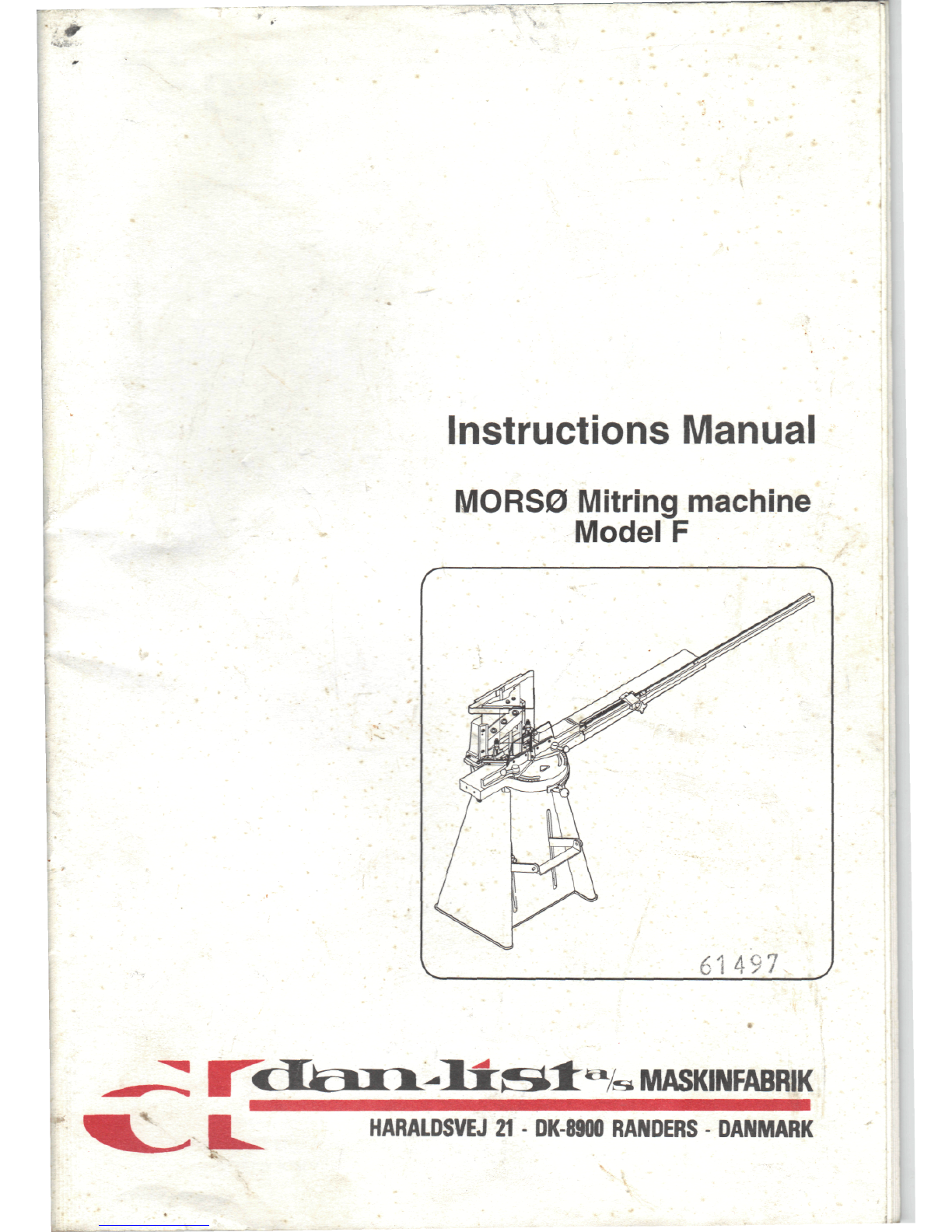
Instructions
manual
MORS0
Mitringmachine
Model
F
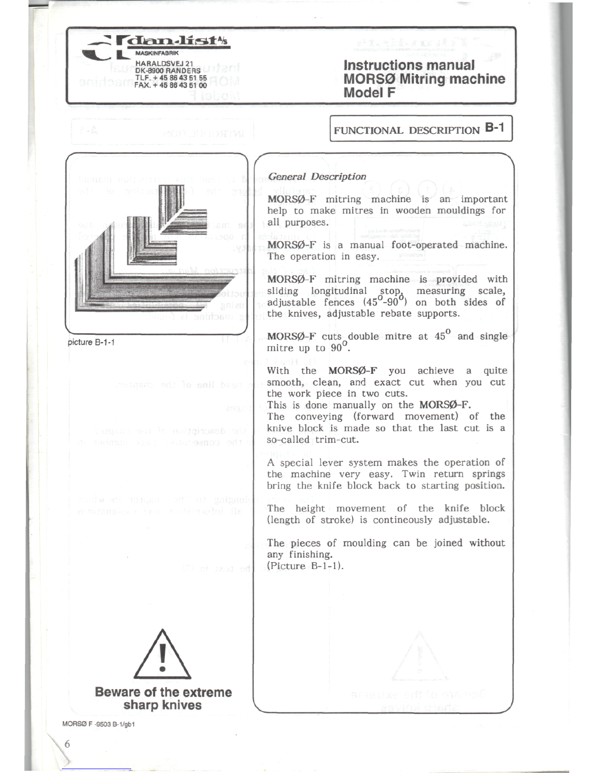
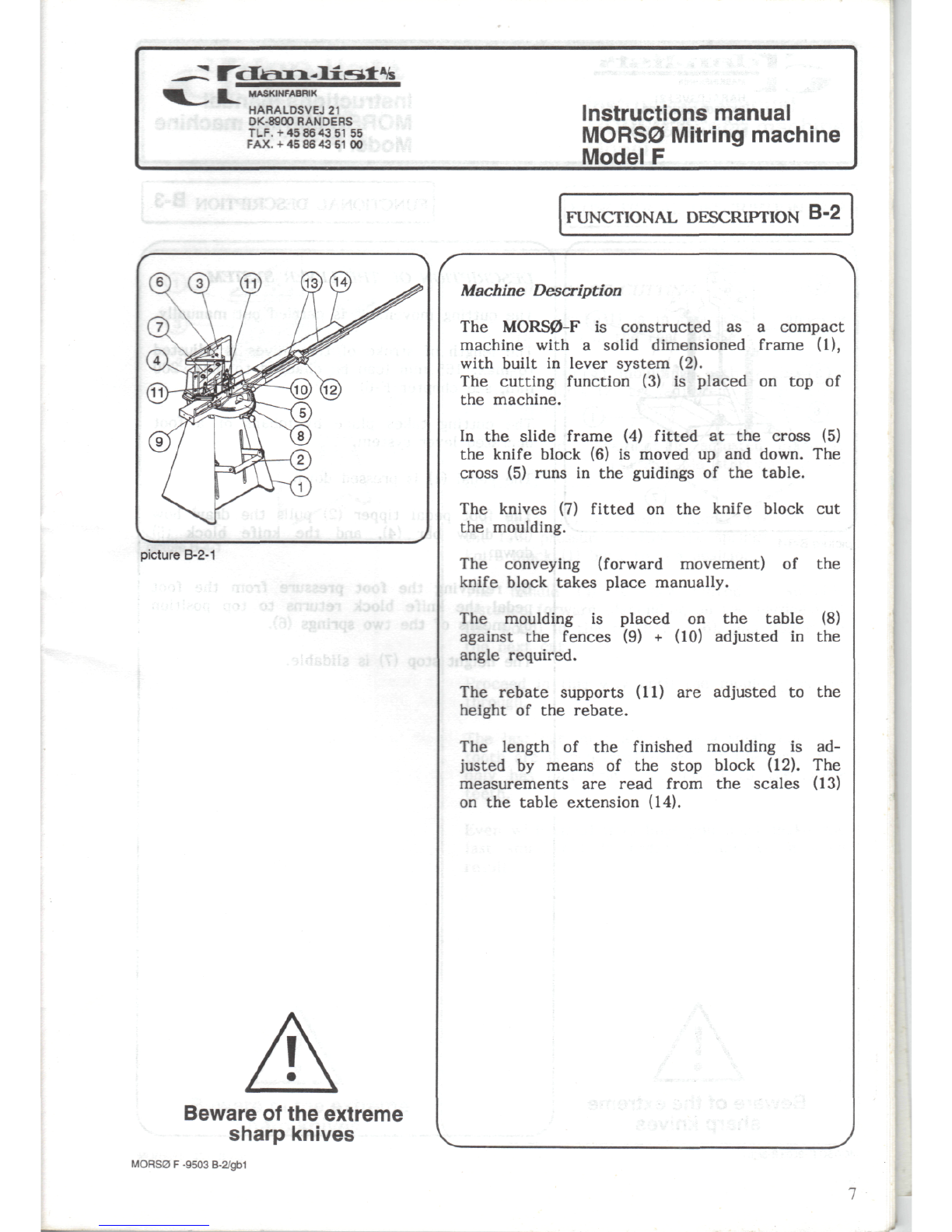
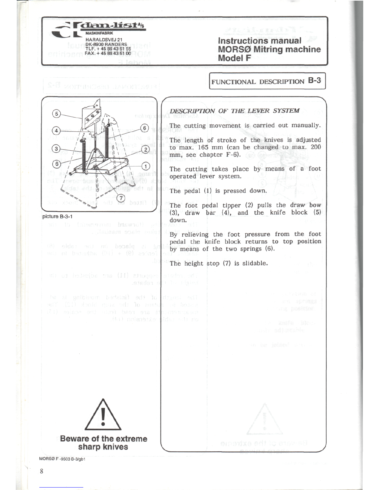
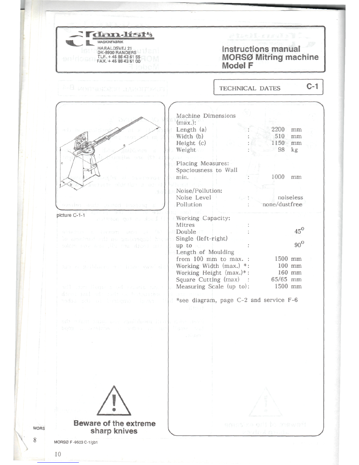
picture
B-1-1
FUNCTIONAL
DESCRIPTION
B-1
Beware
of
the
extreme
sharp
knives
General
Description
MORS0-F
mitringmachine
isan
important
help
to
make
mitres
in
woodenmouldings
for
all
purposes.
MORS0-F
isa
manualfoot-operatedmachine.
The
operation
in
easy.
MORS0-F
mitringmachine
is
providedwith
sliding
longitudinalstop,measuring
scale,
adjustable
fences
(45°-90
) on
both
sides
of
the
knives,adjustable
rebate
supports.
MORS0-F
cuts
double
mitre
at45and
single
mitre
upto
90°.
With
the
MORS0-F
you
achieve
a
quite
smooth,clean,
and
exact
cut
when
youcut
the
work
piece
intwo
cuts.
This
is
donemanually
onthe
MORS0-F.
The
conveying
(forward
movement)
ofthe
knive
block
is
made
so
that
the
last
cutisa
so-called
trim-cut.
A
special
lever
system
makes
the
operation
of
the
machinevery
easy.
Twinreturnsprings
bring
the
knife
blockback
to
startingposition.
The
heightmovement
ofthe
knife
block
(length
of
stroke)
is
contineouslyadjustable.
The
pieces
of
moulding
canbe
joinedwithout
any
finishing.
(PictureB-1-1).
MORS0
F
-9503
B-1/gb1