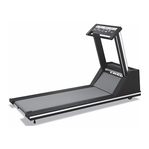
Mortara Quinton CR60 User manual

TABLE OF CONTENTS
REF 042101-001Rev C
CR60
REHABILITATION TREADMILL
SERVICE MANUAL
Manufactured by Mortara Instrument, Inc., Milwaukee,Wisconsin U.S.A.
CAUTION: Federallaw restricts this device to sale by oron theorderofa physician.

Copyright © 2013
by Mortara Instrument, Inc.
7865 N. 86th Street
Milwaukee, Wisconsin 53224
Thisdocument contains confidential informationthat belongsto Mortara Instrument,Inc. No part ofthisdocument
may be transmitted,reproduced,used,or disclosed outside ofthe receiving organizationwithout the express written
consent of Mortara Instrument, Inc. Mortara is a registered trademark of Mortara Instrument, Inc. Quinton is a
registered trademark of Mortara Instrument, Inc.

i
TABLE OF CONTENTS
PREFACE ................................................................................................................................ 1
GENERAL STATEMENTS.......................................................................................................... 2
TECHNICAL SUP PO RT AND SERVICE ...........................................................................................................................................2
NOTICES ................................................................................................................................. 3
MANUFACTURER’S RESPONSIBILITY..........................................................................................................................................3
RESPONSIBILITY OF THE CUS TO M E R..........................................................................................................................................3
EQUI PM ENT IDENTIFICATION...................................................................................................................................................3
COPYRIGHT AND TRADEM ARK NOTICES.....................................................................................................................................3
OTHER IMPORTANT INFORMATION...........................................................................................................................................3
WARRANTY INFORMATION...................................................................................................... 5
YOUR MORTARA WARRANTY ..................................................................................................................................................5
USER SAFETY INFORMATION .................................................................................................. 7
CAUTI ONS AND WARNINGS.....................................................................................................................................................7
EQUIPMENT SYMBOLS AND MARKINGS................................................................................... 9
SYMBOL DEFINITIONS.............................................................................................................................................................9
ELECTROMAGNETIC COMPATABILITY (EMC)..........................................................................11
INTRODUCTION......................................................................................................................15
OVERVIEW..........................................................................................................................................................................15
COMPO NENTS.....................................................................................................................................................................16
Configuration Plate.....................................................................................................................................................16
Power...........................................................................................................................................................................16
Operation....................................................................................................................................................................16
Controllers...................................................................................................................................................................16
THEORY OF OPERATION ........................................................................................................17
OVERVIEW..........................................................................................................................................................................17
Controller Assembly....................................................................................................................................................17
Headframe Assembly.................................................................................................................................................17
Deck and Roller Assembly ..........................................................................................................................................17
CONTROLLER ASSEMBLY .......................................................................................................................................................18
Key Panel.....................................................................................................................................................................18
User Inputs..................................................................................................................................................................18
OutputDisplays...........................................................................................................................................................18
Additional Functions...................................................................................................................................................18
HEADFRAME AS SEM BLY........................................................................................................................................................19
Input Power Module...................................................................................................................................................19
Drive Board .................................................................................................................................................................19
Drive Motor Assemb l y ................................................................................................................................................19
Grade MotorAssembly and System..........................................................................................................................19
DECK AND ROLLER ASSEMBLY................................................................................................................................................19
TROUBLESHOOTING ..............................................................................................................21
DIAGNOSIS..........................................................................................................................................................................21

TABLE OF CONTENTS
ii
TOOLS................................................................................................................................................................................21
ELECTRICAL PROBLEM S .........................................................................................................................................................22
ELECTRONIC PROBLEM S ........................................................................................................................................................23
Error Cod es ..................................................................................................................................................................23
SERVICE MODE....................................................................................................................................................................24
Enter/Exit Service Mode.............................................................................................................................................24
Controller Keys............................................................................................................................................................24
Displays.......................................................................................................................................................................25
Speed/Grade (Open-Loop Mode)...............................................................................................................................25
S p eed ...........................................................................................................................................................................25
Grade...........................................................................................................................................................................25
Testing Pin Signalson the Communications Cable...................................................................................................26
MECHANICAL PRO BLEMS ......................................................................................................................................................26
Walking Belt................................................................................................................................................................26
Drive Belt.....................................................................................................................................................................27
Treadmill Noise...........................................................................................................................................................27
FLOW CHARTS.....................................................................................................................................................................27
Bus Voltage FlowChart..............................................................................................................................................28
Grade Error Flow Chart ..............................................................................................................................................29
Drive Motor Error Flow Chart ....................................................................................................................................30
Communications Link.................................................................................................................................................31
Grade Problems Flow Chart.......................................................................................................................................32
REPAIR/REPLACEMENT AND CALIBRATION............................................................................33
ELECTRICAL SHOCK ...............................................................................................................................................................33
BURNS ...............................................................................................................................................................................33
MECHANICAL HAZARDS ........................................................................................................................................................34
TOOLS................................................................................................................................................................................34
REMOVING THE TREADMILL HOOD.........................................................................................................................................35
REPLACING THE CONFIGURATION PLATE .................................................................................................................................37
Field Functional Test...................................................................................................................................................38
REPLACING THE POWER CO RD ...............................................................................................................................................38
Hard-wired Cords (Low Voltage Units)......................................................................................................................38
Detachable Cords (High Voltage Units).....................................................................................................................38
Field Functional Test...................................................................................................................................................38
REPLACING THE AC DRIVE MODULE .......................................................................................................................................38
Field Functional Test...................................................................................................................................................39
REPLACING THE TENSI O NER...................................................................................................................................................40
Field Functional Test...................................................................................................................................................40
REPLACING THE POLY-V DRIVE BELT ......................................................................................................................................41
Field Functional Test...................................................................................................................................................41
REPLACING THE DRIVE MOTOR..............................................................................................................................................41
REPLACING THE TRA NSFORMER .............................................................................................................................................43
Field Functional Test...................................................................................................................................................43
REPLACING THE GRADE MOTOR ............................................................................................................................................43
Field Functional Test...................................................................................................................................................44
REPLACING THE GRADE MOTOR CHAIN...................................................................................................................................45
Field Functional Test...................................................................................................................................................45
REPLACING THE GRADE POTENTIOMETER (POT).......................................................................................................................45
Grade Pot Wires..........................................................................................................................................................46
Field Functional Test...................................................................................................................................................47
REMOVING THE RACK GEARS.................................................................................................................................................47


TABLE OF CONTENTS
iii
Reassembling the Rack Gears....................................................................................................................................48
Field Functional Test...................................................................................................................................................49
REPLACING A JAMMED RACK GEAR ........................................................................................................................................49
Field Functional Test...................................................................................................................................................50
REPLACING THE PI NI ON SHAFT...............................................................................................................................................50
Field Functional Test...................................................................................................................................................51
ADJUSTING THE GRADE LIMIT SWITCHES.................................................................................................................................51
Field Functional Test...................................................................................................................................................52
WALKI NG DECK ASSEMBLY ...................................................................................................................................................52
REPLACING ROLLERS.............................................................................................................................................................52
Field Functional Test...................................................................................................................................................53
REPLACING THE WALKING BELT .............................................................................................................................................53
Field Functional Test...................................................................................................................................................54
REPLACING COMPRESSION MOUNTS ......................................................................................................................................54
Field Functional Test...................................................................................................................................................54
REPLACING THE DECK ...........................................................................................................................................................55
Field Functional Test...................................................................................................................................................55
ADJUSTI NG THE WALKI NG BELT .............................................................................................................................................55
Belt Tension.................................................................................................................................................................55
Method 1: Using Calipers..........................................................................................................................................55
Method 2: WithoutCalipers......................................................................................................................................56
Walking Belt Tracking................................................................................................................................................56
CONTROLLER ASSEMBLY .......................................................................................................................................................57
Removing the Enclosure.............................................................................................................................................57
Field Functional Test...................................................................................................................................................58
Replacing the PCBA....................................................................................................................................................58
Configuring the Controller..........................................................................................................................................58
Field Functional Test...................................................................................................................................................58
Removing the Key Panel.............................................................................................................................................59
Replacing the Controller Cable..................................................................................................................................59
Field Functional Test...................................................................................................................................................59
Cumulative Use...........................................................................................................................................................59
Distance.......................................................................................................................................................................59
Time.............................................................................................................................................................................60
Limited Access Switch.................................................................................................................................................60
Disabling the Limited Access Switch..........................................................................................................................60
CALIBRATION PROCEDURES ...................................................................................................................................................60
Grade Potentiometer (Pot) Calibration.....................................................................................................................60
Speed Calibration........................................................................................................................................................61
Grade Calibration .......................................................................................................................................................61
PREVENTATIVE MAINTENANCE ..............................................................................................63
RECOMMENDED SERVICE......................................................................................................................................................63
ROUTINE MAINTENANCE ......................................................................................................................................................63
Visual Inspection.........................................................................................................................................................63
CLEANING THE TREADMILL SURFACES .....................................................................................................................................63
Disinfection.................................................................................................................................................................64
VACUUM I NG UNDER THE TREADMILL HOOD ...........................................................................................................................64
Frequency....................................................................................................................................................................64
REPLACEMENT SCHEDULES ....................................................................................................................................................64
ELECTRICAL TESTI NG ............................................................................................................................................................64

TABLE OF CONTENTS
iv
S P ECIF I CAT I ONS ....................................................................................................................66
MEDTRACK CR60 REHABI LITATION TREADM I LL.......................................................................................................................66
POWER REQUIREMENTS .......................................................................................................................................................66
SPEED VS.WEIGHT RANGE ...................................................................................................................................................67
MEDTRACK CONTROLLER......................................................................................................................................................67
PERCENT VS ANGLE RELATIONSHIP FOR TREADMILL GRADE .......................................................................................................69
PART NUMBERS.....................................................................................................................70
FINAL ASSEMBLIES...............................................................................................................................................................70
PART NUMBERS BY CATEGO RY...............................................................................................................................................70
PART NUMBERS BY LOCATION................................................................................................................................................71
FIELD FUNCTIONAL TESTS.....................................................................................................76
COMPLETE FIELD FUNCTI O NAL TEST.......................................................................................................................................76
Test A: Test the Controller Displays..........................................................................................................................76
Test B: Test the Multi Display ...................................................................................................................................77
Test C: Test the Controller Operation.......................................................................................................................77
Test D: Test the Grade Operation.............................................................................................................................78
Test E: Test Speed Operation ....................................................................................................................................78
Test F: Test the Deck Friction ....................................................................................................................................79
Test G: Test the Walk Belt Operation.......................................................................................................................79
Test H: Shut Down the Treadmill..............................................................................................................................79
FIELD TEST NO.1 ................................................................................................................................................................79
FIELD TEST NO.2 ................................................................................................................................................................79
FIELD TEST NO.3 ................................................................................................................................................................81
FIELD TEST NO.4 ................................................................................................................................................................81
FIELD TEST NO.5 ................................................................................................................................................................81
DRAWINGS.............................................................................................................................83
WIRING DIAGRAMS..............................................................................................................................................................83

1
PREFACE
This manualcontainsinformationfor servicing andrepairingthe Quinton®CR60 Rehabilitation treadmill to the
module level. The manualcovers domestic andinternationalversions of the treadmill.
The manual is written for authorized service personnelwith propertraining. There are no user-serviceable parts in
the tread mills . A ny attempt by non-authorized personnelto service the treadmillcan void the warranty. For service
information,callMortara-Quinton Technical Support: 888-MORTARA.
Use this manualonly forservicing the CR60treadmill. Do not use this manualforservicingother
Qu inton treadmills .

2
GENERAL STATEMENTS
Technical Support and Service
Headquarters
Mortara Instrument, Inc.
7865 North 86th Street
Milwaukee, WI 53224
U.S.A.
Tel: 414.354.1600
Tel: 800.231.7437
Fa x: 414.354.4760
Internet: http://www.mortara.com
European Union
Representative
Mortara Rangoni Europe, S rl
(European Headquarters)
Via Cimarosa 103/105
40033 Casalecchio diReno (BO)
Italy
Tel: +39.051.298.7811
Fa x: +39.051.613.3582
Service/Technical
Support Group
Mortara Instrument, Inc.
7865 North 86th Street
Milwaukee, WI 53224
U.S.A.
Tel: 414.354.1600
Service: 888.MORTARA
(888.667.8272)
Fa x: 414.354.4760
E-mail: techsupport@mortara.com
Sales Support/
Supplies & Accessories
Mortara Instrument, Inc.
7865 North 86th Street
Milwaukee, WI 53224
U.S.A.
Tel: 414.354.1600
Fa x: 414.354.4760
HospitalCustomers: orders.us@Mortara.com
Physician Practice: orderspc.us@Mortara.com
US Distribution: orderspc.us@Mortara.com
Mortara InstrumentGermany
Bonifaciusring15
45309 Es s en
Germany
Tel: +49.201.18 55 69 70
Fa x: +49.201.18 55 69 77
Mortara InstrumentNetherlands
Postbus 324
5680 AH Best
Indus trieweg 160b
5683 CG Best
Netherlands
Tel: +31.499.377310
Fa x: +31.499.377908
Mortara InstrumentAustralia
PO Box 7568
Baulkham Hills NSW 2153
Unit 28, 9 Hoyle Avenue
Cas tle Hill NSW 2154
Aus tralia
Tel: +61 2 8070 9303
Fa x: +61 2 9899 9478
Mortara Dol by UK Ltd.
Units 11 & 12, Scion House
Stirling University Innovation Park
Stirling FK9 4NF
Scotland
Tel: +44.1786.444980
Fa x: +44.1786.446630

3
NOTICES
Manufacturer’s Responsibility
Mortara Ins trument, Inc. is responsible for the effects on safety and performance only if:
•Assembly operations,extensions,readjustments,modifications,orrepairs are carried out by persons authorized
by Mortara Instrument,Inc.
•The device is used in accordance with the instructions foruse.
•The electricalinstallationofthe relevantroomcomplies with the requirements of appropriate regulations.
Responsibility of the Customer
The user of this device is responsible for ensuringthe implementationof a satisfactory maintenance schedule.
Failure to do so may cause unduefailure and possible healthhazards.
Equipment Identification
Mortara Instrument,Inc. equipment is identified by a serialand reference numberon the backof the device. Care
shouldbe taken so that thesenumbers are notdefaced.
Copyright and Trademark Notices
This document contains information that is protected bycopyright. Allrights are reserved. No part ofthis
documentmay be photocopied, reproduced,ortranslated to anotherlanguagewithout priorwritten consent of
Mortara Ins trument, Inc.
Other Important Information
The information in this documentis subjectto change without notice.
Mortara Instrument,Inc.makes no warrantyofany kind with regard to this materialincluding,butnotlimited to,
implied warranties of merchantability and fitnessfor a particular purpose. Mortara Instrument, Inc. assumes no
responsibility forany errors oromissions that may appearin this document. Mortara Instrument,Inc.makes no
commitment to update orto keep currentthe information containedin this document.

NOTICES
4

5
WARRANTY INFORMATION
Your Mortara Warranty
MORTARA INSTRUMENT, INC. (hereafter referred to as “Mortara”) warrantsthat componentswithin Mortara
products (hereafter referred to as “Product/s”) will be free from defects in workmanship and materials forthe
numberofyears specified ondocumentation accompanying the product,orpreviously agreedto by thepurchaser
and Mortara,orif not otherwise noted,fora period ofthirteen(13)months fromthe date ofshipment.
Consumable,disposable orsingle use products s uch as , b ut n ot limit ed t o , PA PER o r ELECTRODES are warranted
to be free from defectsin workmanship andmaterials fora period of90 days fromthe date ofshipmentorthe date
of first use, whichever is sooner.
Reusable productsuchas,but notlimited to,BATTERIES, BLOOD PRESSURE CUFFS, BLOOD PRESSURE
HOSES, TRANSDUCER CABLES, Y-CA BLES, PA TIENT CA BLES, LEA D W IRES, M A GNETIC STORA GE
MEDIUMS, CARRY CASES or MOUNTS,are warranted to be free fromdefects in workmanship andmaterials for
a period of90 days.This warrantydoesnot apply to damage to the Product/scaused byanyorall ofthe following
circumstancesorconditions:
a) Freight damage;
b) Supplies, accessories and internalparts NOT approvedby Mortara;
c) Misapplication,misuse,abuse,and/orfailure to followthe Product/sinstruction sheetsand/orinformation
guides;
d) Accident;
e) A disasteraffectingtheProduct/s;
f) Alterations and/ormodifications tothe Product/s notauthorized by Mortara;
g) Otherevents outside ofMortara’s reasonable controlornot arising undernormaloperatingconditions.
THE REMEDY UNDER THIS WARRANTY IS LIMITED TO THE REPAIR OR REPLACEMENT WITHOUT
CHARGE FOR LABOR OR MATERIALS, OR ANY PRODUCT/S FOUND UPON EXAMINATION BY
MORTARA TOHAVE BEEN DEFECTIVE. This remedy shallbe conditioneduponreceiptofnotice byMortara of
any alleged defects promptly after discovery thereof within the warranty period. Mortara’s obligations under the
foregoing warrantywillfurtherbe conditioneduponthe assumptionby thepurchaseroftheProduct/s(i)ofall carrier
charges with respect to anyProduct/s returnedtoMortara’s principalplaceor any otherplaceas specifically designated
by Mortara oran authorized distributororrepresentative ofMortara,and(ii) all risk of loss in transit. It is expressly
agreed that the liability of Mortara is limited and that Mortara does not function as an insurer. A purchaser of a
Product/s, by its acceptance and purchase thereof, acknowledges and agrees that Mortara is not liable for loss, harm,
or damage due directly orindirectly toan occurrenceorconsequence there fromrelating to the Product/s. IfMortara
should be foundliable to anyone underany theory (except the expressedwarrantysetforth herein)forloss,harm,or
damage, the liability of Mortara shall be limited to the lesser of the actual loss, harm, or damage, or the original
purchase price ofthe Product/swhen s old.

WARRANTY INFORMATION
6
EXCEPT A S SET FORTH HEREIN W ITH RESPECT TO REIM BURSEM ENT OF LA BOR CHA RGES, A
PURCHA SER’S SOLE EXCLUSIVE REM EDY A GA INST M ORTA RA FOR CLA IM S RELA TING TO THE
PRODUCT/S FOR ANY AND ALL LOSSES AND DAMAGES RESULTING FROM ANY CAUSE SHALL BE
THE REPA IR OR REPLACEMENT OF DEFECTIVE PRODUCT/S TO THE EXTENT THAT THE DEFECT IS
NOTICED AND MORTARA IS NOTIFIED WITHIN THE WARRANTY PERIOD. IN NO EVENT, INCLUDING
THE CLA IM FOR NEGLIGENCE, SHA LL M ORTA RA BE LIA BLE FOR INCIDENTA L, SPECIA L, OR
CONSEQUENTIAL DAMAGES, OR FOR ANY OTHER LOSS, DAMAGE, OR EXPENSE OF
ANY KIND, INCLUDING LOSS OF PROFITS, WHETHER UNDER TORT, NEGLIGENCE OR STRICT
LIABILITY THEORIES OF LAW, OR OTHERWISE. THIS WARRANTY IS EXPRESSLY IN LIEU OF ANY
OTHER WARRANTIES, EXPRESS OR IMPLIED, INCLUDING, BUT NOT LIMITED TO THE IMPLIED
WARRANTY OF MERCHANTABILITY AND THE WARRANTY OF FITNESS FOR A PARTICULAR
PURPOSE.

7
USER SAFETY INFORMATION
W a rni ng:
Means there is thepossibility ofpersonalinjury to youorothers.
Caution:
Meansthere is thepossibility of damage to thepatient monitor.
Note:
Provides informationto further assistin the useofthe patientmonitor.
NOTE: This manual may containscreenshots and pictures. Any screen shots and pictures are provided
for reference only and are not intended to convey actual operating techniques. Consult the actual screen in
the host language for specific wording.
Cautions and Warnings
•Read this manualin full before operating the treadmill.
•Before each use ofthis equipment,checkthepowerreceptacle forsigns ofdamage. Do not operate the
equipment ifthe integrity of these items is in question.
•Regularly inspect cables and treadmill belts forwear or damage.Do not operate the equipment if the integrityof
thes e items is in qu est ion.
•The treadmill must be on an appropriate, dedicatedelectricalcircuit with a powerrating thatmeets the electrical
specificationon the treadmillserialnumberlabel. Nothing else shouldbe connectedto thecircuit.
•To avoid potentialsafety andelectrical problems, useparts andaccessories thatmeet specifications as notedin
this service manual.
•Use of accessories or cables other than thosespecified, with the exceptionof accessories orcables sold by
Quinton Cardiology,Inc.as replacement parts for internal components, may result in increasedemissions or
decreasedimmunity ofthe treadmill.
•This equipmentis classified ClassI,Type B, ordinary equipment,not protectedagainst fluid ingress.It is rated
for continuous operation.
•The treadmill needsspecialprecautions regardingEMCand needs to be installed andputinto service according
to the guidelines of the EMCdeclaration tables.
•Portable and mobile RF communications equipment may affect thetreadmill and the recommendedseparation
distances in the EMCdeclarationtables should be observed.
•The treadmill should notbe usedadjacent to otherequipment.Ifadjacent use is necessary,thetreadmill should
be observedto verify normaloperation in the configuration in which it will be used.
•Do not operatethis equipmentin the presence offlammable anesthetic mixt u re s .
•Increasedriskdue to leakagecurrent canresult ifthis equipment is notgrounded properly.

USER SAFETY INFORMATION
8
•Failure to follow these guidelines can producea serious orpossibly fatalelectricalshockhazard. Consult a
qualified electrician as required.
•Do not start the treadmillwhen someone is standingon the belt.
•Keep speedandgrade at the lowestsettings when getting onand offthe treadmillbelt.
•Neverplace chairs or otherobjects on treadmills.
•Keep the area underneathand aroundthe treadmillclear. Make sure cables are clearofthe treadmill.
•Be aware of a moving treadmill belt.
•Allowsufficient roomforusers to maneuveraround thesystemand to safely mountanddismount thetreadmill.
•Ensure the userunderstandsthepropertreadmillmount and dismountprocedure.
•The user should straddle the treadmillbelt or standon thedeck’s edge at start up.
•The usershould alwaysface the front ofthetreadmill when steppingon oroffthe belt.Do not steponto thebelt
while facing the side of the treadmill.
•When finished, the usershould hold the handrailand step offto the side ofthe treadmill.
•Properly train new staff.

9
EQUIPMENT SYMBOLS AND MARKINGS
Symbol Definitions
Quinton productsdisplay one ormore ofthe following symbolsand warning labels foryourprotection.No single
prod uct dis plays all.
Attention: Consult accompanying
docum ent s
Earth ground (protective)
Off (power disconnected from mains)
Type B equipment – provides adequate protection
against electric shock, particularly regarding
allowable leakage current; reliability of the
protective earth connection (when present)
On (power connectedto mains)
Type BF equipment – contains an F-type isolated
patient applied part providing a high degree of
protection against electric shock
Alternating current
T ype BF equipment with defibrillat ion prot ect ion
High voltage
Type CF equipment – contains an F-type isolated
patient applied part and provides a degree of
protection against electric shock higher than that
for type BF equipment regarding allowable
leakage currents
Earth ground (functional)
T ype CF equipment with defibrillat ion prot ect ion
Replace fuse only as marked Fuse
Mains power
Equipotentiality
D o wn Up
Faster
Slo wer
Warning TT imed fuse (slo-blo)

EQUIPMENT SYMBOLS AND MARKINGS
10
Hz Hertz VVo l t s
AAmperes VA Volt Amperes

11
ELECTROMAGNETIC COMPATABILITY (EMC)
Table X-1 Guidance and Manufacturer’s Declaration: Electromagneti c Em issi on s
The Medtrack Rehabilitation Treadmills are intendedfor use in the electromagnetic environmentspecified below.
The customeror the userofthe Medtrack Rehabilitation Treadmills should assurethat theyare usedin suchan
environment.
Emissions Test Compliance Electromagnetic Environment: Guidance
RF Emissions
CISPR 11
Group 1
The Medtrack Rehabilitation Treadmills use RF energy only for
its internal function. Therefore, its RF emissions are very low
and are not likely to cause any interference in nearby electronic
equipment.
RF Emissions
CISPR 11
Class A
The Medtrack Rehabilitation Treadmills are suitable f or use in all
establishments other than domestic and those directly
connected to the public low -voltage pow er supply netw ork that
supplies buildings used for domestic purposes.
Harmonic Emissions
IEC 61000-3-2
Class A
Voltage Fluctuations/
Flicker Emissions
IEC 61000-3-3
Complies
NOTE Tests verified w ith shielded input/output cables only.

ELECTROMAGNETIC COMPATABILITY(EMC)
12
Table X-2 Guidance and Manufacturer’s Declaration: Electromagnetic Immunity
The MedtrackRehabilitation Treadmills are intendedforuse in the electromagnetic environmentspecified below.
The customerorthe user ofthe Medtrack Rehabilitation Treadmills should assurethattheyare usedin suchan
environment.
Imm unity Test IEC 60601 Test Level Compliance Level
Electromagnetic Environment:
Guidance
Electrostatic
discharge (ESD)
IEC 61000-4-2
+ 6 kV contact
+ 8 kV air
+ 6 kV contact
+ 8 kV air
Floors should be w ood, concrete, or
ceramic tile. If floors are covered w ith
synthetic material, the relative humidity
should be at least 30%.
Electrical f ast
transient/burst
IEC 61000-4-4
+ 2 kV f or
pow er supply lines
+ 1 kV f or
input/output lines
+ 2 kV f or
pow er supply lines
+ 1 kV f or
input/output lines
Mains pow er quality should be that of a
typical commercial or hospital
environment.
Surge
IEC 61000-4-5
+ 1 kV differential mode
+ 2 kV common mode
+ 1 kV differential mode
+ 2 kV common mode
Mains pow er quality should be that of a
typical commercial or hospital
environment.
Voltage dips,
short
interruptions and
voltage
variations on
pow er supply
input lines
IEC 61000-4-11
<5% UT (>95% dip in
UT) for 0.5 cycles
<40% UT (>60% dip in
UT) for 5 cycles
<70% UT (>30% dip in
UT) for 25 cycles
<5% UT (>95% dip in
UT) for 5 sec
<5% UT (>95% dip in
UT) for 0.5 cycles
<40% UT (>60% dip in
UT) for 5 cycles
<70% UT (>30% dip in
UT) for 25 cycles
<5% UT (>95% dip in
UT) for 5 sec
Mains pow er quality should be that of a
typical commercial or hospital
environment. If the user of the
MedTrack treadmill requires continued
operation during pow er mains
interruptions, it is recommended that
the MedTrack treadmill be pow ered
from an uninterruptible pow er supply or
a battery.
Pow er frequency
(50/60 Hz)
magnetic field
IEC 61000-4-8
3 A/m
3 A/m
Pow er frequency magnetic fields
should be at levels characteristic of a
typical location in a typical commercial
or hospital environment.
NOTE 1: UT is the AC Mains voltage priorto applicationofthe test level.
NOTE 2: Tests verified with shielded input/output cables only.

ELECTROMAGNETIC COMPATABILITY(EMC)
13
Table X-3 Guidance and Manufacturer’s Declaration: Electromagnetic Immunity
The MedtrackRehabilitation Treadmills are intendedforuse in the electromagnetic environmentspecified below.
The customer or the user of the MedtrackRehabilitation Treadmills should assurethattheyare usedin suchan
environment.
Imm unity Test
IEC 60601 Test
Level
Compliance
Level Ele ctrom agnetic Environment: Guidance
Conducted RF
EN 61000-4-6
3 V r ms
150 kHz to
80 MHz
3 V
Portable and mobile RF communications equipment
should be used no closer to any part of the MedTrack
treadmill, including cables, than the recommended
separation distance calculated from the equation
applicable to the frequency of the transmitter.
Recommended separation distance
d = 1.2
d = 1.2 80 MHz to 800 MHz
d = 2.3 800 MHz to 2.5 GHz
Where P is the maximum output pow er rating of the
transmitter in w atts (W) according to the transmitter
manufacturer and d is the recommended separation
distance in meters (m).
Field strengths from fixed RF transmitters, as
determined by an electromagnetic site surveya, should
be less than the compliance level in each frequency
rangeb.
Interf erence may occur in the vicinity of equipment
marked w ith the follow ing symbol:
Radiated RF
IEC 61000-4-3
3 V/m
80 MHz to
2.5 GHz
3 V/m
NOTE 1: At 80 MHz and 800 MHz, the higherfrequency rangeapplies.
NOTE 2: These guidelines may not apply in all situations. Electromagnetic propagation is affected by
absorptionandreflectionfromstructures,objectsand people.
NOTE 3: Tests were verifiedwithshielded input/output cables only.
a. Field strengths from fixed transmitters, such as base stations for radio (cellular/cordless) telephones and land
mobile radios, amateur radios, AM and FM radio broadcast, and TVbroadcast cannot be predicted theoretically
with accuracy. To assess the electromagnetic environment due to fixed RF transmitters, an electromagnetic site
survey should be considered. If the measured field strength in the location in which the MedTrack treadmill is
used exceeds the applicable RF compliance level above, the MedTrack treadmill should be observed to verify
normaloperation. If abnormalperformance is observed, additionalmeasures may benecessary, suchas reorienting
or relocating the MedTracktreadmill.
b. Over the frequency range 150 kHz to 80 MHz, field strengths s hould be les s than [3] V/m.

ELECTROMAGNETIC COMPATABILITY(EMC)
14
Table X-4 Recommended Separation Distances Between Portable and Mobile RF Communications
Equipment and the Medtrack Rehabilitation Treadmills
The Medtrack Rehabilitation Treadmills are intendedforuse in an electromagnetic environment in which radiated
RF disturbancesare controlled.The customerorthe userofthe Medtrack Rehabilitation Treadmills can help prevent
electromagnetic interference bymaintaininga minimum distance betweenportable and mobile RFcommunications
equipment (transmitters)and the Medtrack Rehabilitation Treadmills as recommended below, according to the
maximum output powerofthe communications equipment.
Rated Maximum Output
Power of Transmitter (W) Separation Distance According to Frequency of Transmitter (m)
150 KHz to 80 MHz 80 MHz to 800 MHz 800 MHz to 2.5 GHz
d = 1.2 d = 1.2 d = 2.3
0.01 0.12 0.12 0.23
0.1 0.38 0.38 0.73
1 1.2 1.2 2.3
10 3.8 3.8 7.3
100 12 12 23
Fortransmitters rated at a maximum outputpowernot listedabove, the recommended separationdistance d in
meters (m) can be estimated usingthe equation applicable to the frequency of the transmitter, where Pis the
maximum output powerrating ofthetransmitterin watts (W) according to the transmitter manufacturer.
NOTE 1: At 80 MHz and 800 MHz,the higherfrequency rangeapplies.
NOTE 2: These guidelines may not apply in all situations. Electromagnetic propagation is affected by
absorptionandreflection from structures, objects, and people.
NOTE 3: Tests were verifiedwithshielded input/output cables only.
Other manuals for Quinton CR60
1
Table of contents
Other Mortara Treadmill manuals