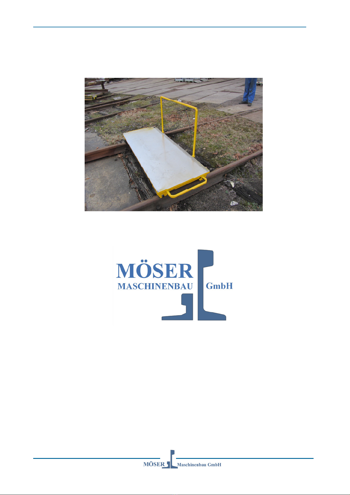
Operating instructions aluminium trolley Ro-V 282
2
contents
1. How to use this manual..............................................................................................3
2. Pleas note....................................................................................................................4
2.1 Foreword ...............................................................................................................4
2.2 Safety instructions .................................................................................................7
2.2.1 Use for intended purpose ...............................................................................7
2.2.2 Use of skilled personnel .................................................................................7
2.2.3 Working clothes..............................................................................................8
2.2.4 Operating safety instructions ..........................................................................8
2.2.5 Loads..............................................................................................................9
2.2.6 Entering and leaving the machine ..................................................................9
2.2.7 Safety notes in this manual ..........................................................................10
2.2.8 Preconditions for safety................................................................................11
2.2.9 Personnel .....................................................................................................11
2.2.10 Mechanical dangers .....................................................................................13
3. Description and explanation....................................................................................14
3.1 Technical specifications.......................................................................................14
3.2 General drawing ..................................................................................................15
3.2.1 Trolley in clearance profile German and Norwegian railway.........................16
3.3 Main frame/axle bridges ......................................................................................17
3.4 Rail wheels ..........................................................................................................18
3.4.1 Wheel profile ................................................................................................19
3.5 On track braking system......................................................................................20
3.5.1 Technical specifications................................................................................20
Maintenance and repair...................................................................................................22
3.6 General information .............................................................................................22
3.7 Regular checks and maintenance .......................................................................24
3.8 Self made repairs or attachments........................................................................26
4. Spare parts................................................................................................................27
5. Risk analysis.............................................................................................................29
6. Declaration of conformity ........................................................................................31
6.1 EG – Konformitätserklärung ................................................................................32