Neutronics H1301 User manual

Model H1301 Recovery and Recycling System
Installation, Operation and Maintenance Manual
Revision-L September, 2019
Page 2 of 105
Table of Contents page
I. Unpacking and Inspection 4
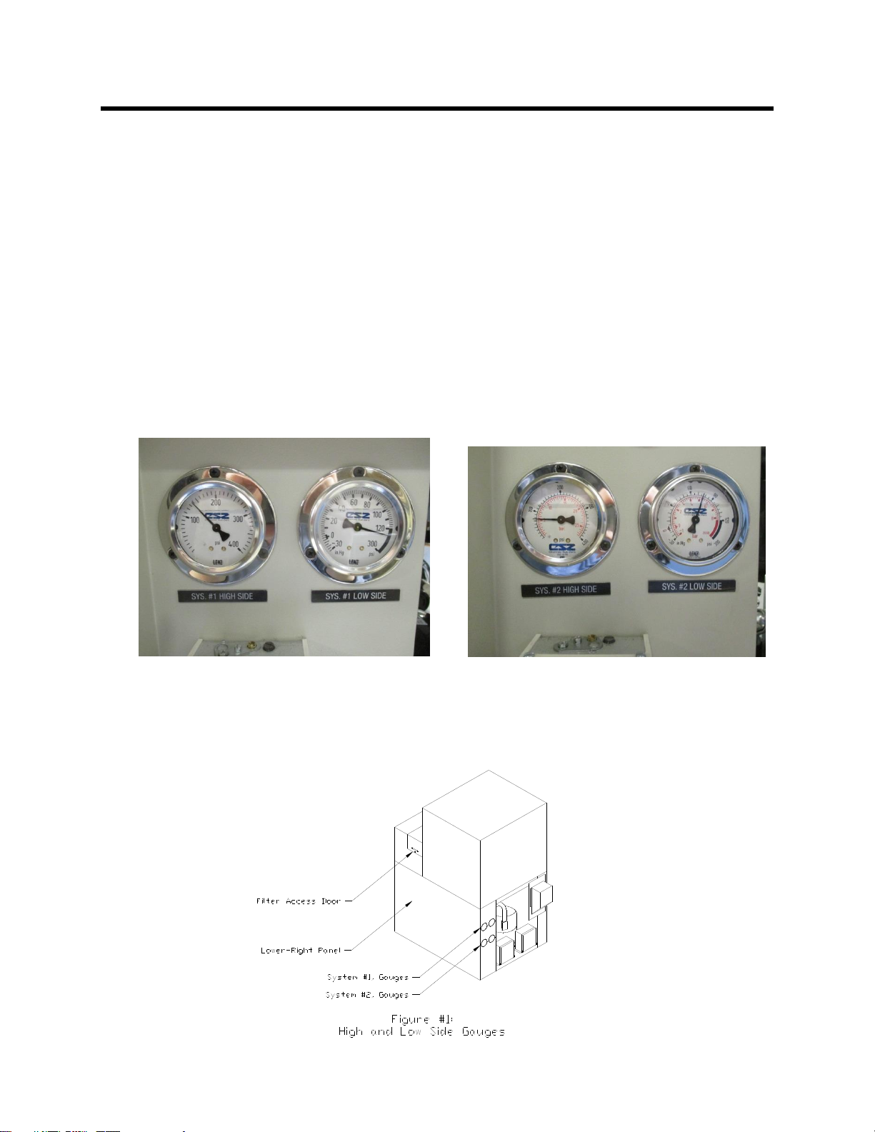
Figure #1: High and Low Side Gauges 4
II. System Warnings 5
A. General Safety Issues 5
B. Installation Warnings 5
C. Operation Warnings 6
D. Maintenance Warnings 7
III. General System Description 8
Figure #2: System Component Overview 8
IV. System Installation 9
Figure #3: Dimensional Reference 9
A. Machine Location 10
Figure #4: Port Locations 10
B. Pressure Relief Valve 11
C. Electrical Supply Requirements 12
D. Nitrogen Vent Port 13
E. Nitrogen Supply 14
F. Agent Receiver Storage Container Connections 15
G. Agent Source Container Connections 19
V. System Operation and Controls 22
A. Manual Overrides and System Control Description 22
Figure #5: Front Control Panel Detail 23
B. Initial System Start-Up Procedure 26
C. Inlet Pressure Switch Description and Adjustments 28
D. Automatic System Operation 32
E. Disconnecting the Source Container When it is not Empty 35
F. Receiving Container Replacement 36
G. System Shutdown 37
VI. System Operation Description and Component Review 38
A. PLC Status Indicators 38
B. The Nitrogen Vent Cycle 39
C. Inlet Recovery Review 40
D. Filtration Review 40
E. Nitrogen Separation Review 41
F. Pump Out Review 42
(Table of Contents Continues on Next Page)

Model H1301 Recovery and Recycling System
Installation, Operation and Maintenance Manual
Revision-L September, 2019
Page 3 of 105
Table of Contents (continued) page
VII. System Maintenance Procedures 43
A. Recommended Spare Parts Listing 43
B. Recommended Maintenance Schedule 43
Figure #7: Recommended Maintenance Schedule 43
C. Moisture Indicator Inspection 44
D. Particulate Filter Indicators 44
E. Cooling System Pressures 45
F. Vapor Compressor Oil Maintenance 46
Figure #8: Vapor Compressor Sight Glass Oil Level 46
Figure #9: Vapor Compressor Component Identification 48
G. Condenser Coil Cleaning 49
H. Moisture, Acid and Processed Particulate Filter Element Replacement 50
Figure #10: Exploded Filter Details 53
Figure #11: Filtration Component Identification 54
I. Inlet Particulate Filter Replacement 55
J. Heat Exchanger Evacuation 57
Figure #12: Processing Tank Component Details 58
K. Complete System Evacuation 59
Figure #13: Outlet Component Identification 63
L. System Leak Testing 65
M. Pressure Controller Calibration 66
Figure #14: 4-20mA Loop Component Locations 66
Figure #15: Pressure Controller Detail 67
Figure #16: Loop Power Supply Detail 70
Figure #17: Pressure Transmitter Testing 73
N. Process Temperature Controller Calibration 78
Figure #18: Process Temperature Components 78
Figure #19: Temperature Controller Detail 79
Figure #20: Temperature Controller and Probe 82
O. Vapor Compressor Oil Renewal 85
P. Cooling System Controller Setting 87
Figure #21: Cooling System Controller Detail 87
Q. Inlet Vacuum Switch Calibration 91
Figure #22: Vacuum Switch Test Plumbing 91
Figure #23: Inlet Vacuum Switch Detail 92
R. Outlet Section Maintenance 93
VIII. System Troubleshooting Guide 94
A. Error Code Description 94
B. Machine Will Not Operate 96
C. Cooling System Will Not Operate 96
D. Cooling System is Not Cooling Properly 96
E. System Ready Lamp Will Not Illuminate 96
F. Machine Will Not Perform Inlet Processing 97
G. Machine Will Not Evacuate Source 98
H. Machine Will Not Vent 98
I. Machine Will Not Pump Out 98
J. Solenoid Valve Troubleshooting 99
K. Liquid Pump Troubleshooting 100
L. Liquid Level Switch Troubleshooting 102
M. Vapor Compressor Troubleshooting 103
IX. System Specifications 104
X. System Warranty 105

Model H1301 Recovery and Recycling System
Installation, Operation and Maintenance Manual
Revision-L September, 2019
Page 4 of 105
I. Unpacking and Inspection
A. Upon receipt of the system, visually inspect the shipping carton for signs of
damage or mishandling. Immediately contact the carrier for an inspection if the
shipping carton is damaged or evidence of mishandling exists.
B. Carefully remove the outer crating materials. Care must be taken during
unpacking to avoid enclosure damage or scratching.
C. Inspect the system for dents, scratches, or other evidence of mishandling during
shipment. Request an immediate inspection from the carrier if damage is evident.
D. Inventory the contents of the shipping carton against the packing list provided
with the shipping documents.
E. Observe the pressure indications of the Refrigeration Section: System #1- High
and Low side and System #2 –High and Low side pressure gauges located at
the lower-rear panel of the machine: refer to figure #1 below. Pressure
indications below 130 psi for system #1 and below 65 psi for system #2 may
indicate a break in the plumbing: Contact the factory for further assistance.
F. Open the Filter Access Door located at the top-right corner of the Control Panel
Black Hood. Using an inspection light source visually verify the integrity of the
internal tubing contained under the Hood. Close the Filter Access Door.

Model H1301 Recovery and Recycling System
Installation, Operation and Maintenance Manual
Revision-L September, 2019
Page 5 of 105
II. System Warnings
The following lists warnings concerning the installation, operation, and maintenance of the
system as well as general safety issues. The warnings listed here are both specific and
generalized and may or may not be repeated throughout the manual
A. General Safety Issues
KEEP AWAY FROM LIVE ELECTRICAL CIRCUITS. Operating personnel should
observe all safety precautions at all times. Do not replace components or make
adjustments inside the equipment with the high voltage energized to the system unless
directed to do so in the maintenance sections of this manual. Dangerous potentials exist
internal to the system and under certain conditions may exist even with the system power
switch in the off position.
DO NOT SERVICE OR ADJUST THE SYSTEM ALONE. All maintenance or
system adjustments should be accomplished in the presence of someone capable of
rendering aid in the unlikely event of injury.
ONLY PERMIT FULLY TRAINED PERSONEL TO OPERATE THE SYSTEM.
COMPLETELY READ AND UNDERSTAND THIS MANUAL BEFORE
ATTEMPTING INSTALLATION, OPERATION, OR MAINTENANCE TO THE
EQUIPMENT.
ALWAYS WEAR SAFETY GLASSES when operating the equipment or working with
the Agent containers.
B. Installation Warnings
DO NOT INSTALL THE SYSTEM IN AN OUTDOOR ENVIRONMENT. The
system is designed for indoor locations with ambient temperature from 70 to 80 degrees F
(21.1to 26.7C).
DO NOT LOCATE THE SYSTEM NEAR DRIPPING, SPRAYING, OR
STANDING MOISTURE OR WATER. The system enclosure IS NOT NEMA rated.
Contact with moisture and water may result in electrical short circuits which may cause
health and system hazards.
ALWAYS LOCATE THE SYSTEM ON AN EVEN AND LEVEL SURFACE, use
wheel chocks to insure the machine will not roll if accidentally pushed, or roll from
operational vibration.
ALWAYS MAINTAIN A SERVICE AREA OF 3-FEET AROUND ALL SIDES OF
THE MACHINE to provide adequate ventilation of the refrigeration section.
ALWAYS ATTEMPT TO LOCATE THE SYSTEM IN AN AREA THAT IS
COOL, DRY, AND AWAY FROM DIRECT SUNLIGHT.
DO NOT LOCATE THE EQUIPMENT IN OR NEAR THE VICINITY OF FLAMMABLE
MATERIALS OR VAPORS.
DO NOT CONNECT THE EQUIPMENT TO ANY POWER SOURCE OTHER THAN
SPECIFIED BY THE INSTALLATION PROCEDURES OF THIS MANUAL. FOLLOW
LOCAL AND NATIONAL SAFETY CODES WHEN INSTALLING THE EQUIPMENT.
ALWAYS ATTEMPT TO MAINTAIN A MINIMUM 3/16” INSIDE DIAMETER
PLUMBING CONNECTIONS TO THE PORTS OF THE MACHINE WITH A MINIMUM
OF BENDS, LOOPS, LOW SPOTS, OR SAGS.

Model H1301 Recovery and Recycling System
Installation, Operation and Maintenance Manual
Revision-L September, 2019
Page 6 of 105
II. System Warnings (continued)
C. Operation Warnings
DO NOT OPERATE THE EQUIPMENT WITH THE EXTERNAL PANELS
REMOVED.
DO NOT RESTRICT THE FLOW OF AIR THROUGH THE ENCLOSURE
GRATES.
DO NOT INTRODUCE ANY SUBSTANCE OTHER THAN AGENTS HALON
1301, HALON 1211, FM200, FE25 OR CLEAN DRY NITROGEN GAS INTO THE
EQUIPMENT.
DO NOT INTRODUCE AGENT INTO THE EQUIPMENT THAT IS KNOWN TO
EXCEED THE FOLLOWING CONTAMINATION LEVELS:
Moisture in excess of 100 PPM
Oil in excess of 500 PPM
Acid in excess of 80 PPM
Particulates in excess of 80 PPM
DO NOT INTRODUCE AGENT INTO THE EQUIPMENT THAT IS
CONTAMINATED WITH SUBSTANCES OTHER THAN MOISTURE, OIL,
ACID, PARTICULTES NITROGEN OR AIR. The equipment is only capable of
removing the aforementioned contaminates and WILL NOT purify Agent contaminated
with other substances.
DO NOT EXCEED INPUT PRESSURES GREATER THAN 600 PSIG
PROPERTY DAMAGE AND INJURY MAY RESULT.
NEVER OPERATE THE SYSTEM WITHOUT AN EXTERNAL STORAGE
VESSAL CONNECTED TO THE OUTPUT PORT OF THE SYSTEM. Failure to
connect a storage container to the outlet port of the machine could result in total loss of
recovered Agent.
NEVER OPERATE THE SYSTEM WITHOUT A SOURCE OF AGENT OR
CLEAN DRY NITROGEN CONNECTED TO THE INLET PORT OF THE
SYSTEM. Failure to connect a source container to the inlet port of the machine may
result in the introduction of ambient air into the system that will saturate the moisture
filters and cause ice formation and internal blockage to the machine.
DO NOT RESTRICT THE NITROGEN VENT PORT OF THE MACHINE.
Restricting the vent port may result in poor recycling quality.
ALWAYS SECURE THE SOURCE CONTAINER BEFORE DISCHARGE OF
THE CONTAINER. Source containers such as system tanks may be under extreme
pressures and will present a hazardous condition if not properly handled by trained
personnel.
ALWAYS EVACUATE EMPTY EXTERNAL STORAGE VESSALS AND
ASSOCIATED PLUMBING TO A 2500-MICRON MINIMUM VACUUM LEVEL
BEFORE PROCESSING AGENT THROUGH THE MACHINE.

Model H1301 Recovery and Recycling System
Installation, Operation and Maintenance Manual
Revision-L September, 2019
Page 7 of 105
II. System Warnings (continued)
D. Maintenance Warnings
ALWAYS EVACUATE THE EQUIPMENT TO A MINIMUM VACUUM LEVEL
OF 1000 MICRONS WHENEVER THE SYSTEM PLUMBING HAS BEEN
INVADED AND EXPOSED TO AMBIENT AIR. Failure to properly evacuate the
system will result in moisture freezing internal to the system causing ice blockage, liquid
level switch and or outlet pump failure.
NEVER OPEN THE ENCLOSURE OF THE EQUIPMENT WITH THE
EQUIPMENT CONNECTED TO THE MAIN POWER SOURCE.
DO NOT REPLACE COMPONENTS OR MAKE ADJUSTMENTS INSIDE THE
EQUIPMENT WITH THE EQUIPMENT OPERATIONAL unless directed to do so
by the maintenance sections of this manual.
NEVER INVADE THE INTERNAL PLUMBING OF THE EQUIPMENT
BEFORE VERIFICATION OF LOW PLUBMING PRESSURE.
ALWAYS PERFORM A COMPLETE SYSTEM EVACUATION SECTION-VII. K
of this document BEFORE CHANGING PROCESSING FROM ONE TYPE OF
AGENT TO ANOTHER TYPE OF AGENT.

Model H1301 Recovery and Recycling System
Installation, Operation and Maintenance Manual
Revision-L September, 2019
Page 8 of 105
III. General System Description
The Recovery/Recycling machine will recover and clean fire extinguishing Agents of
moisture, acid, oil, particulate, and non-condensable gases, and pump the cleaned Agent
into user storage containers.
Agent refers any of the types of fire extinguishing media that may be recovered using the
recycling system: Halon 1301, Halon 1211, FM200 or FE25.
The recovery machine is comprised of five major component groups, contained in the one
enclosure, as depicted by figure-2. Each component group will provide the functions
necessary to recover, recycle and pump out Agent with a minimum of operator
involvement.
A temperature controller regulates the temperature of the internal processing tank by
operating the cascade refrigeration section.
During automatic processing, a programmable controller (PLC) receives input information
regarding the status of the source container and the internal processing tank. Based on
this information the PLC operates the components required for the appropriate actions of
recovery and recycling. The PLC also monitors the process and will indicate error
conditions by suspending operation and flashing the processing lamp with one, or a
combination of the liquid level lamps, located on the front panel, indicating the error
condition detected. See section-VIII.A for a description of the error codes.

Model H1301 Recovery and Recycling System
Installation, Operation and Maintenance Manual
Revision-L September, 2019
Page 9 of 105
IV. System Installation
The user is urged to carefully study the following installation procedures and fully
understand them BEFORE attempting installation of the recovery/recycling system. Refer
to figure-3 below for the physical dimensions of the machine. Clearance of 3-feet is
recommended on all sides of the machine.
Weight: 1000 US pounds (453.6 Kg)

Model H1301 Recovery and Recycling System
Installation, Operation and Maintenance Manual
Revision-L September, 2019
Page 10 of 105
IV. System Installation (continued)
A. Machine Location
Position the machine on a clean, level surface and use wheel chocks to insure that
the machine will not roll if accidentally pushed, or roll from operational vibration.
Maintain a service area of at least 3-feet around all sides of the machine to allow for
proper air circulation.
The ports of the machine are ¼” x 45SAE Male Flare fittings. Refrigeration service
hoses of the appropriate length may be used to connect to the ports of the machine.
ALWAYS LOCATE THE SYSTEM ON AN EVEN AND LEVEL SURFACE.
DO NOT INSTALL THE SYSTEM IN AN OUTDOOR ENVIRONMENT. The
system is designed for indoor locations with ambient temperature from 70 to 80 degrees F
(21.1to 26.7C).
DO NOT LOCATE THE EQUIPMENT IN OR NEAR THE VICINITY OF
FLAMMABLE MATERIALS OR VAPORS.
DO NOT LOCATE THE SYSTEM NEAR DRIPPING, SPRAYING, OR
STANDING MOISTURE OR WATER. The system enclosure IS NOT NEMA rated.
Contact with moisture and water may result in electrical short circuits which may cause
health and system hazards.
ALWAYS LOCATE THE SYSTEM IN AN AREA THAT IS COOL, DRY, AND
AWAY FROM DIRECT SUNLIGHT.
ALWAYS ATTEMPT TO MAINTAIN A MINIMUM 3/16” INSIDE DIAMETER
PLUMBING CONNECTIONS TO THE PORTS OF THE MACHINE WITH A MINIMUM
OF BENDS, LOOPS, LOW SPOTS, OR SAGS.

Model H1301 Recovery and Recycling System
Installation, Operation and Maintenance Manual
Revision-L September, 2019
Page 11 of 105
IV. System Installation (continued)
B. Pressure Relief Valve Port
The Pressure Relief Valve port of the machine is a 5/8” x 45SAE Male Flare fitting
located on the top of the machine see figure-4. The port is fitted with a plastic plug to keep
dirt and debris out of the valve. This plastic plug will be ejected if the valve operates. DO
NOT CONNECT ANY PLUMBING OR CAP TO THE PRESSURE RELIEF VALVE
PORT. This is a safety device that will prevent rupturing of the internal processing tank
due to an over pressure condition. If the internal pressure exceeds 300 psi, the valve will
open releasing the vapor side of the tank to maintain the internal pressure to below 300
psi.
WARNING! Do Not Plug or Restrict the Pressure Relief Valve at the top of the
machine. Damage to the Machine, Property Damage and Injury May
Result.

Model H1301 Recovery and Recycling System
Installation, Operation and Maintenance Manual
Revision-L September, 2019
Page 12 of 105
IV. System Installation (continued)
C. Electrical Supply
NOTE: It is the customer’s responsibility to comply with all local and national electric
codes and safety requirements when installing the electrical service for the machine.
The following requirements are intended only to address the issues of the machine
operation.
WARNING: DO NOT CONNECT THE EQUIPMENT TO ANY POWER SOURCE
OTHER THAN THAT SPECIFIED BY THIS MANUAL.
The main power cable must reach the electrical service location without undue
stress or tension on the cord and the cord must be routed away from possible contact
with walkways and peripheral moving equipment.
A check mark will appear below in the box next to the required electrical service for
the machine. The specific schematic drawings have been inserted into a pocket at the end
of this section of the manual. The electrical requirement is also listed on the serial number
label located in the upper-left corner on the rear panel of the machine.
208-230 VAC/60Hz, single phase, 9.0 KVA service
Electrical Schematic SC-E-0316
230 VAC/50hZ, single phase, 9.0 KVA service
Electrical Schematics SC-E-0425 and SC-E-0382
240 VAC/50hZ, single phase, 9.0 KVA service
Electrical Schematics 020043 and SC-E-0779
The power circuit for the machine should be protected with dual circuit breakers or
fuses that will limit the maximum current to the machine to 50 amps.
The machine is supplied with a ten foot #8 AWG 3-wire power cable terminated with a
USA NEMA 2-pole 3-wire ground plug.
The mating receptacle for the plug is a USA NEMA type 6-50R 2-pole 3-wire ground
receptacle, Hubble part number 9367 or equivalent.

Model H1301 Recovery and Recycling System
Installation, Operation and Maintenance Manual
Revision-L September, 2019
Page 13 of 105
IV. System Installation (continued)
D. Nitrogen Vent Port
The Nitrogen Vent port of the machine is a ¼” x 45SAE Male Flare fitting at the end of
a deflector tube located on the left side of the machine see figure-4. The tube is curved
downward to direct the stream of venting nitrogen away from personnel and to channel
condensation down and away from contact with the automatic valve of the machine.
Remove the cap and the bagged Deflector Tube from the Vent port.
Connect the Deflector Tube to the Vent Port finger tight. Then just lightly tighten snug with
a 5/8” open end wrench. Do not over tighten: this may twist the internal plumbing of the
machine.
The vent port must be plumbed to an outside area when processing FE25. Use
minimum 3/16” inside diameter plumbing. Be sure to route the plumbing so that moisture
condensing inside the plumbing will drain out and not back to the machine otherwise the
nitrogen vent valve may freeze in the open position resulting in total loss of the processing
Agent. Install screening at the end of the plumbing to guard against entry and clogging by
debris and insects.
CAUTION: DO NOT RESTRICT THE NITROGEN VENT PORT OF THE
MACHINE. Restricting the vent port may result in poor recycling quality.

Model H1301 Recovery and Recycling System
Installation, Operation and Maintenance Manual
Revision-L September, 2019
Page 14 of 105
IV. System Installation (continued)
E. Nitrogen Supply
Clean and dry commercial grade nitrogen gas will be required for system operation.
Evacuate the plumbing to a 2500 micron minimum vacuum level before opening the
nitrogen supply to the machine.
The nitrogen supply must be regulated to no greater than 250 PSIG. Connecting a
supply greater than 250 PSIG to the Nitrogen Supply Port may cause the pressure relief
valve inside the machine to activate.
The Nitrogen Supply port and Evacuation Port are located at the top of the machine.
The connections are interchangeable use either valve for nitrogen or evacuation.
Two shut off valves are provided with ¼” x 45° SAE male flare connectors.
Evacuation and Leak Testing Method:
1. Remove the valve caps and set aside.
2. Connect the nitrogen gas source to one of the valves. Do not open the nitrogen
cylinder.
3. Connect a vacuum pump and vacuum gauge to the remaining valve.
4. Open both valves, with the nitrogen source closed, and operate the vacuum pump to
achieve a 2500 micron vacuum level: this will remove air from the interconnecting
plumbing.
5. Close the valve connected to the vacuum pump. Discontinue vacuum pump operation
and disconnect the vacuum pump from the valve. Reconnect the valve cap back to the
valve.
6. Open the nitrogen gas source regulated from 140 to 250 PSI with the valve of the
machine remaining opened.
7. Leak test the plumbing connections using leak detect fluid. If no leakage is detected the
nitrogen installation is complete, or repair any leaks if required, then repeat the evacuation
procedure.
WARNING: DO NOT CONNECT GAS IN EXCESS OF 250 PSIG TO THE
NITROGEN SUPPLY PORT OF THE MACHINE. DAMAGE TO THE
EQUIPMENT MAY RESULT.

Model H1301 Recovery and Recycling System
Installation, Operation and Maintenance Manual
Revision-L September, 2019
Page 15 of 105
IV. System Installation (continued)
F. Receiver Storage Container Connections
NOTE: It is the customer’s responsibility to comply with all local and national safety
requirements and codes for the selection of storage and shipping containers used to
capture the recovered Agent. The following requirements are intended only to address
the issues of the machine operation.
The Receiver Storage Container must be installed onto a weigh scale or be able to
be weighed to avoid an overfill condition of the container.
Process Connections: Connect the Vapor Port of the storage container to the OUTLET
Port of the machine. The storage container must be either evacuated to a 2500 micron
minimum vacuum level or contain clean Agent prior to processing.
Evacuation and Leak Testing The plumbing connections should first be tested for
leakage using clean dry nitrogen from 200 to 250 psi then evacuated to a 2500-micron
vacuum level using a vacuum pump through the evacuation valve fitted to the outlet port
of the machine.
OUTLET PORT EVACUATION VALVE
CAUTION: Failure to leak test the plumbing connections could result in total loss of
recovered Agent.
CAUTION: Failure to evacuate the storage container and plumbing connections will
result in contamination of the recovered Agent and unexpected high
pressure in the storage container.
CAUTION: Operation of the machine without a storage container connected to the
Outlet Port of the machine will result in total loss of recovered Agent.
During the pump-out cycle, the machine will pump recycled liquid Agent from the Outlet
Port of the Machine into the storage container. Nitrogen gas will also pressurize the
internal processing tank of the machine through the Nitrogen Supply Port. This is required
to prime the liquid pumps of the machine.

Model H1301 Recovery and Recycling System
Installation, Operation and Maintenance Manual
Revision-L September, 2019
Page 16 of 105
.
IV. System Installation (continued)
F. Receiver Storage Container Connections (continued)
Outlet Leak Testing and Evacuation Method:
1. Connect the Vapor Port of the storage container to the Outlet Port of the machine.
The storage container is placed on a weigh scale.
2. DO NOT OPEN the storage container valve.
3. Pressurize the plumbing through the Outlet Evacuation Valve with 200 to 250 psi
nitrogen gas and leak test the plumbing connections with leak detect fluid.
A hose connection from the Nitrogen Supply Evacuation Valve may be used to
pressurize the plumbing in place of using a second source of nitrogen gas.
Nitrogen Supply Connected
Connect Nitrogen Supply Evacuation Valve to
Outlet Evacuation Valve. Open the valves to
pressurize for leak testing.

Model H1301 Recovery and Recycling System
Installation, Operation and Maintenance Manual
Revision-L September, 2019
Page 17 of 105
IV. System Installation (continued)
F. Receiver Storage Container Connections (continued)
Outlet Leak Testing and Evacuation Method (continued)
4. Close the Outlet Evacuation Valve.
5. Shut off the nitrogen gas.
6. Slowly bleed the pressure by loosening then disconnect the nitrogen gas from the
valve.
7. Open the Outlet Evacuation Valve to release the nitrogen pressure.
8. Connect a vacuum gauge and vacuum pump to the open Outlet Evacuation Valve.
If the storage container DOES NOT CONTAIN AGENT: Open the vapor valve of the
storage container: this will evacuate the container along with the plumbing connections
at the same time.
If the storage container HAS SOME AMOUNT OF AGENT IN IT: Leave the storage
container vapor valve closed: otherwise all the agent in the container will be lost.

Model H1301 Recovery and Recycling System
Installation, Operation and Maintenance Manual
Revision-L September, 2019
Page 18 of 105
IV. System Installation (continued)
F. Receiver Storage Container Connections (continued)
Outlet Leak Testing and Evacuation Method (continued)
9. Operate the vacuum pump to achieve a minimum 2500 micron vacuum level indication
on the vacuum gauge.
10. Close the Outlet Evacuation Valve.
11. Discontinue vacuum pump operation.
12. Disconnect the vacuum pump and vacuum gauge from the Outlet Evacuation Valve.
13. Cap the Outlet Evacuation Valve.
14. Open the vapor valve of the storage container if it is closed.
The Receiving Storage Container is now ready for use.

Model H1301 Recovery and Recycling System
Installation, Operation and Maintenance Manual
Revision-L September, 2019
Page 19 of 105
IV. System Installation (continued)
G. Source Container Connections
Source Containers will be installed to the machine to recover and recycle the agent
from the containers. The instructions presented in this section should be
accomplished only when ready to perform the Initial Start-Up procedure section-
V.B. of this document or when ready to begin System Operation as described in
section-V.D. of this document.
The Manual Inlet Valve port and Inlet Evacuation Valve port of the machine are ¼” x
45SAE Male Flare fittings. High pressure rated refrigeration service hoses of the
appropriate length may be used to connect the AGENT source container to the machine.
Inlet Evacuation Valve and Port Manual Inlet Valve and Port
The inlet valve plumbing to the source container must be leak tested before
operating the machine to guard against Agent loss. Leaks in the inlet connections will also
allow ambient air to enter the machine during the vapor recovery cycle.
The source container shall be fitted with a shut-off valve in the event that the source
container must be disconnected from the Inlet Valve of the machine before processing
has been completed.
WARNING! A method must be employed to restrain Agent source containers against
recoil when safety anti-recoil fittings are removed from the containers.
Uncontrolled discharge of pressurized containers will provide high
velocity container recoil resulting in Property Damage, Personal Injury or
Death.
WARNING! Do Not Connect Agent or Nitrogen in excess of 600 psig to the Inlet Port
of the machine. Damage to the Machine May Result.
CAUTION: Failure to leak test the plumbing connections could result in total loss of
Agent.

Model H1301 Recovery and Recycling System
Installation, Operation and Maintenance Manual
Revision-L September, 2019
Page 20 of 105
IV. System Installation (continued)
G. Source Container Connections (Continued)
Inlet Leak Testing and Evacuation Method:
1. Connect the Agent source container to the Manual Inlet Valve Port. Do not open the
source container.
2. Connect nitrogen gas regulated to the pressure of the Agent source container to the
Inlet Evacuation Valve Port.
3. Open the Evacuation Valve and the Manual Inlet Valve to pressurize the plumbing with
the nitrogen and leak test the plumbing connections using leak detect fluid.
4. Shut off the nitrogen, Close the Evacuation Valve and disconnect the nitrogen.
A valve is installed to the
outlet of the source and is
closed.
Source is positioned to expel liquid first
and strapped to floor restraints to protect
against possible container recoil.
High Pressure Hose
Table of contents