manuals.online logo
Brands
  1. Home
  2. •
  3. Brands
  4. •
  5. OTT-JAKOB
  6. •
  7. Industrial Equipment
  8. •
  9. OTT-JAKOB HSK A63-D User manual

OTT-JAKOB HSK A63-D User manual

Popular Industrial Equipment manuals by other brands

ABB +Q957 user manual

ABB

ABB +Q957 user manual

G.B.C BASIC EDGE 50 instruction manual

G.B.C

G.B.C BASIC EDGE 50 instruction manual

Tronair Batpak 11-6602-1000 Operation & service manual

Tronair

Tronair Batpak 11-6602-1000 Operation & service manual

Pilz PNOZ mi2p Operation manual

Pilz

Pilz PNOZ mi2p Operation manual

Clemco Zero BNP 6012 manual

Clemco

Clemco Zero BNP 6012 manual

Erskine Attachments V-Plow Operator's manual

Erskine Attachments

Erskine Attachments V-Plow Operator's manual

ABB HT610965 Operation manual

ABB

ABB HT610965 Operation manual

Morra MH 540 user manual

Morra

Morra MH 540 user manual

Eaton S090ST manual

Eaton

Eaton S090ST manual

GRIGGIO G 240 P4 instructions

GRIGGIO

GRIGGIO G 240 P4 instructions

Nexen AIR CHAMP HT45 user manual

Nexen

Nexen AIR CHAMP HT45 user manual

WTE V5 installation manual

WTE

WTE V5 installation manual

ABB HT845232 Operation manual

ABB

ABB HT845232 Operation manual

SMC Networks CJP Series Operation manual

SMC Networks

SMC Networks CJP Series Operation manual

JohnDow Industries JDI-AFT58 Operator's manual

JohnDow Industries

JohnDow Industries JDI-AFT58 Operator's manual

IMB MB9016A instruction manual

IMB

IMB MB9016A instruction manual

Clarke CUMB1 Assembly & operating instructions

Clarke

Clarke CUMB1 Assembly & operating instructions

amiad Arkal Spin Klin 2 user guide

amiad

amiad Arkal Spin Klin 2 user guide

manuals.online logo
manuals.online logoBrands
  • About & Mission
  • Contact us
  • Privacy Policy
  • Terms and Conditions

Copyright 2025 Manuals.Online. All Rights Reserved.

PRODUCT INFORMATION
CLAMPING UNIT
HSK A63-D
9560018926V00_PE_2018-09 // ENGLISH
OTT-JAKOB Spanntechnik GmbH // Industriestraße 3 7 // D-87663 Lengenwang
+49 83 64 / 98 21 -0 // +49 83 64 / 98 21 -10 // [email protected] // www.ott-jakob.de
PRODUCT INFORMATION
HSK A63-D
TABLE OF CONTENTS
1 PRODUCT DESCRIPTION..........................................................................................................3
1.1 FEATURES.................................................................................................................................3
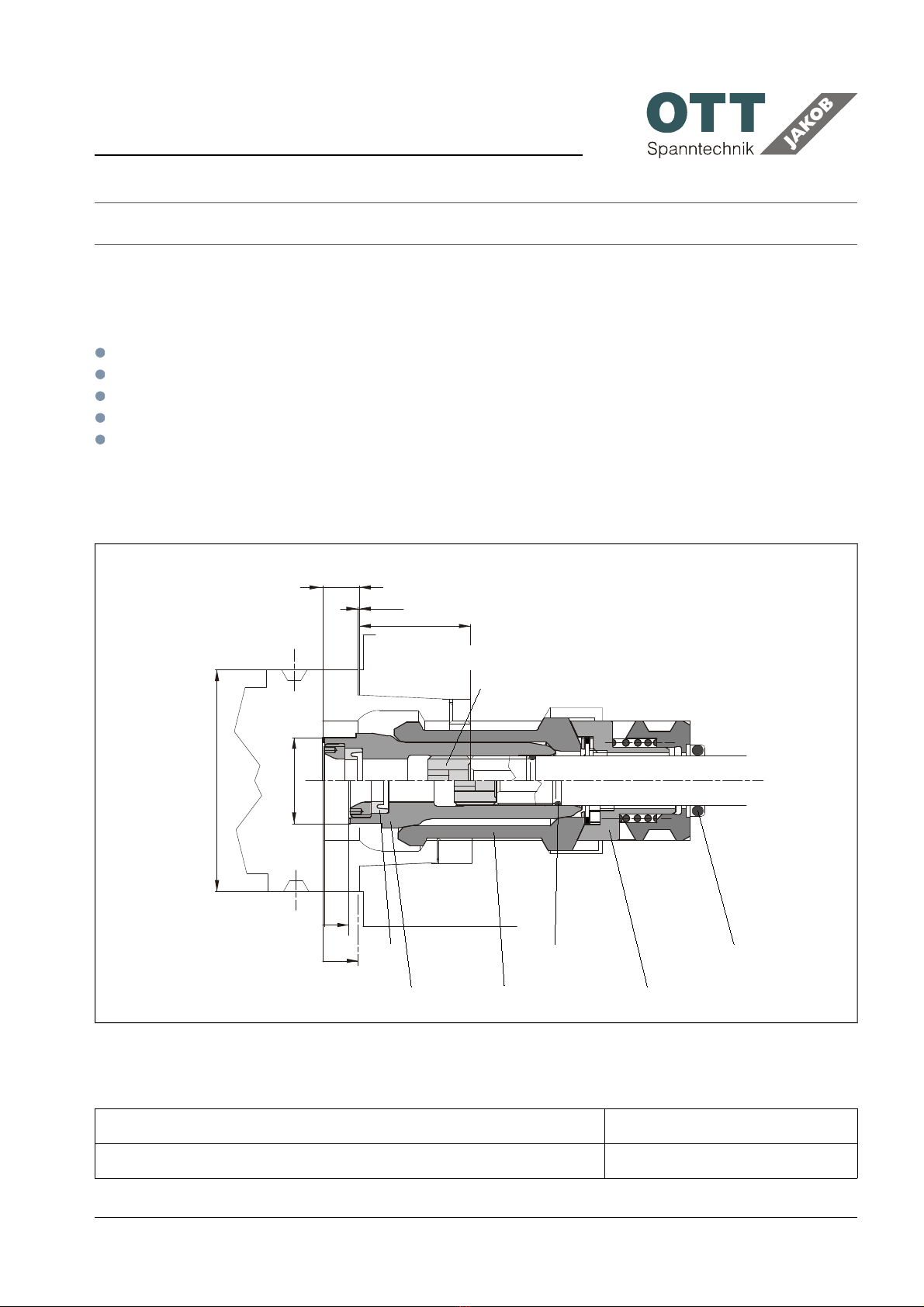
1.2 DIMENSIONS.............................................................................................................................3
1.3 ORDER NUMBER.......................................................................................................................3
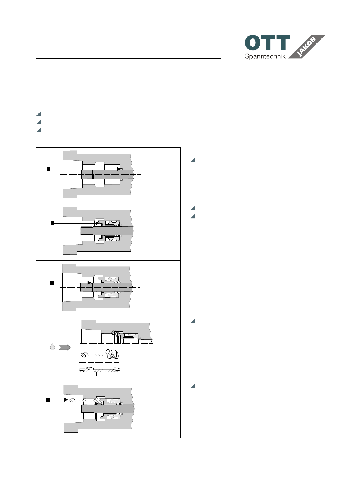
2 ASSEMBLY.................................................................................................................................4
3 OPERATION...............................................................................................................................6
3.1 TOOL INSERTING......................................................................................................................6
3.2 OPERATING CONDITIONS........................................................................................................7
3.3 INTERN COOLING SUPPLY.......................................................................................................7
3.4 COOLANT...................................................................................................................................8
3.5 GENERAL...................................................................................................................................8
4 MAINTENANCE.........................................................................................................................9
4.1 MAINTENANCE INTERVALS.....................................................................................................9
4.2 REGREASE CLAMPING UNIT..................................................................................................10
4.3 E CHANGE OF THE LIP SEAL................................................................................................11
4.4 BREAK OF A GRIPPER SEGMENT..........................................................................................11
4.5 DISASSEMBLE CLAMPING UNIT HSK...................................................................................12
4.6 WEARING PART LIST..............................................................................................................12
4.7 TROUBLE SHOOTING HSK......................................................................................................13
9560018926V00_PE_2018-09
Subject to modification due to technical advance! // 2
symbol explanation:
keep attention -
dangerous!
keep attention -
malfunction!
PRODUCT INFORMATION
HSK A63-D
1 P ODUCT DESC IPTION
1.1 FEATU ES
Higher transmission ratio
Parallel moving gripper segments
High static and dynamic stiffness
Locking geometry
high life expectancy
1.2 DIMENSIONS
1.3 O DE NUMBE
designation order-no
clamping unit HSK A63-D 95.600.189.2.6
9560018926V00_PE_2018-09
Subject to modification due to technical advance! // 3
E.M. 10,5 ± 0,1
A = 0,5
31,5
H0
A
H1
Hmax.
10
7,4
d1 = 63
24
reference gauge
MA = 30 Nm
12 3
gripper
ejection A
lock screw
clamping cone spacer
SW
4
PRODUCT INFORMATION
HSK A63-D
2 ASSEMBLY
Clean spindle inside contour
make sure that edges are properly rounded
grease O-rings
mount o-ring in the spindle
grease spacer with mounting grease
push spacer into spindle and check for ease
of movement
mount o-ring on the drawbar
Protective sleeve obtainable:
95.601.169.4.1
grease area of contact
→ METAFLUX-Paste 70-8508
or
→ KLÜBER-Paste ME 31-52
do not mix the grease!
snap gripper segments in the spacer;
ensure that the numbers match
9560018926V00_PE_2018-09
Subject to modification due to technical advance! // 4
6x / 7x
6x / 7x
PRODUCT INFORMATION
HSK A63-D
grease clamping cone with mounting
grease
Screw the clamping cone (pre-assembled
with seal, protective sleeve and lock screw)
onto the drawbar. Maximum screw in depht
is the gauge dimension, the O-ring is
damaged on the drawbar otherwise
adjust gauge dimension E.M.
gauge dimension:
A63 / B80 / E63 / F80: 10,5 mm
tighten the lock screw
tightening torque:
A63 / B80 / E63 / F80: 30 Nm
Chec after approx. 100 stro es
In unclamped position
Check dimension gauge E.M.
re-tighten through a clamped tool
9560018926V00_PE_2018-09
Subject to modification due to technical advance! // 5
E. M.
Lösestellung!
MA
E.M.
PRODUCT INFORMATION
HSK A63-D
3 OPE ATION
No rotation without clamped tool!
Only use technically perfect tools!
3.1 TOOL INSE TING
Do not insert tool into the spindle taper
when rotating!
The tool has to be inserted all the way
to the plane surface of the clamping
cone to prevent misclamping!
Our recommendation for the
concentricity tolerance for tool
changing as well as the maximum
force on the plane surface on the
clamping cone is shown in the table
below:
standard size A63 / B80 / E63 / F80
concentricity (øG) [mm] 0,8
tool changer force max. [kN] 3,6
9560018926V00_PE_2018-09
Subject to modification due to technical advance! // 6
concentricity tolerance
PRODUCT INFORMATION
HSK A63-D
3.2 OPE ATING CONDITIONS
Avoid additional stress contributed to force from brackets or any other connection and
or support, proximity switches
impact loads < 25 g
the spring must be protected against corrosive media and dirt exposure
the tool interface must be free of chips and substantial cooling lubricant residue
allowable temperature 10° C (on the inside of the spindle)
3.3 INTE N COOLING SUPPLY
Because of possible damage at the coolant tube interface (tube/seal) we recommend
drainage holes in the tool interface area
during installation of tool:
pressure in clamp chamber p < 0,5 bar
In order to minimize wear, the coolant tube at the interface of the gripper assembly
and tool should be shaped as follows:
minimum and easy going and angular flexing (per ISO 12164-1)
ground
Operation with coolant is only permitted if free flow is guaranteed. Therefore, you
must only use tool holders with coolant tubes and tools with coolant thru holes.
Otherwise, it is possible that the spindle gets flooded or the seals are damaged by the
pressure spikes.
9560018926V00_PE_2018-09
Subject to modification due to technical advance! // 7
PRODUCT INFORMATION
HSK A63-D
3.4 COOLANT
Guidelines and technical specifications for the coolant use in the machine:
Coolant use must conform to the current regulations of the legislation and the
professional association.
Our products are to the greatest possible extent protected by the materials used or by
means of a passivated surface against corrosion and therefore suited for use with water.
The rate of corrosion is strongly dependent on the contents of the media
(e.g. chlorine is very much increasing the rate of corrosion), as well as the environment
in which the products are being operated (e.g. the difference in electrical potential
between rotor and stator in spindles).
Suitable protective measures such as the utilization of corrosion inhibitors will extend
the service life in every way.
Furthermore, you must only use coolants which conform with the specs listed on the
table below.
Parameter / test procedure Limited values
Corrosion protection according
to DIN 51360 section 2
No corrosion after 2 hours
Elastomer compatibility No change of the shore hardness and/or the
elongation
OTT-JAKOB applies FKM (VITON®)
Nonferrous metal compatibility No corrosion on copper, brass and aluminum parts
Glue residue after slow
evaporation at 50 degrees
Non sticky! No residue! Easily removable.
3.5 GENE AL
Recommendation: install a limit switch for the drawbar
Follow maintenance intervals!
9560018926V00_PE_2018-09
Subject to modification due to technical advance! // 8
PRODUCT INFORMATION
HSK A63-D
4 MAINTENANCE
4.1 MAINTENANCE INTE VALS
To guarantee the function of the power drawbar the following maintenance intervals must be
adhered to.
Every wee
Check the packing ring in the clamping unit (visual check)
Check the clamping unit if it is polluted or damaged; is it sufficient greased? (visual check)
Please see below:
The regrease cycle depends on the loss of lubrication of the clamping unit.
Cause for the loss of lubrication:
Seal in the clamping cone is defective
Type of medium used can desolve grease
Cleaning spray from outside directly on the clamping unit etc
Regrease clamping unit → # 4.2 // 10
Every six month or after 200.000 tool changes at the latest
In unclamped position: Check dimension gauge E.M.
counter through a clamped tool again.
Test Pull-in-force (we recommend:use POWER-CHECK ):
If the pull-in-force is smaller than 70% of the nominal value, following procedures have to be
performed in the following sequence:
regrease ( → # 4.2 // 10 ) and test pull-in force again
exchange clamping unit and test again
exchange drawbar completely
Every year or after 500.000 tool changes at the latest
Exchange the packing ring → # 4.3 // 11
9560018926V00_PE_2018-09
Subject to modification due to technical advance! // 9
PRODUCT INFORMATION
HSK A63-D
4.2 EG EASE CLAMPING UNIT
Note: take only grease of one company; do not mix the grease!
Regrease in assembled condition
If very dirty: take clamping unit out and clean.
Then grease clamping unit and reassemble → # 2 // 4
Grease for HSK-clamping unit
designation quantum order-no.
* KLÜBER-Fett-Paste ME 31-52 10 g 06.21001.014
KLÜBER-Spray ALTEMP Q NB 50 400 ml 06.21001.015
METAFLUX-Fett-Paste Nr. 70-8508 4 g 0.929100.012
METAFLUX-Moly-Spray Nr. 70-82 400 ml 06.21001.010
* first equipment
Aid for regreasing with paste in mounted state (clamped without tool):
designation HSK-size order-no.
brush A32 - A100 06.16001.001
9560018926V00_PE_2018-09
Subject to modification due to technical advance! // 10
clamped without tool
option
with spray
option
with brush