Mosley S-402-M User manual

-402-M
SSEMBLY INSTRUCTIONS
,
S-402~ 2 Eiement 40 Meter 8eam
OSLEY ELECTRONICS, INC
}325 STYLE ASTER ORIVE
UNJON, O 63084

-402-1'1
The high performance of your Mosley -402-M can only be achieved if
this beam is assembled in accordance with the instructions in this
manual. ubstitutions of materials or modification of design
ill
greatly lessen it's performance.
We recommend that you read through the assembly instructions and
familiarize yourself with each step before assembling your antenna.
PART NUMBER
-,
:
4
S
SA
6
7
8
9
10
1 1
12
13
13A
14
15
16
16A
17
18
19
0
21
24
5
26
27
8
2'3
;:::0
31
I
I
I
~--
QUANTITY
2
60
4
4
16
4
8
-,
:
16
16
6
4
4
16
4
2
1
4
1
6
2
4
"
:
1
1
10
10
10
-,
:
ITEM
ORIVEN ELEMENT UPPoRT
A
36'A
1N ULAToR
#1O LoCI<I")A HER
10/32 X 1-1/2" MACH. CREW
1-3/8/ )::.05E:::<72
u
1-1/4"x. 058::<72"
10/3
x
1}
SS Screw
Coil Mounting Bracket
2" U-Bolts 5/16
#48 Clamping Blocks
5/16 Lock washers
5/1E.Nuts
1
u/:::co:::
Hex Nuts
1-1/8"x.O 8x72",coded RED
1-1/8"x.O 8x72", coded BLUE
#8 SS Sheet Melal Screw
1-1/8" End Caps
1.768x.12 x24", Boom splice
1.768x.12 x48", Boom plice
2" Boom ection Color coded
Mast Plat.e
#47 Clamping Blocks
2" Bocl[('End Caps
1-~/8" Inner Element Cap s
older Lugs, #1021
Radiatc!}-'Coi 1
Reflecte!}'Coil
1/4-20 Bolts, 2-1/2"
1/4-20 Lock washers
1/4-20 Nut.s
WARRANTY CARO
IN TRUCTIoN MANUAL
PENETRO X
DEBURRING NoTICE
WARNING NoTICE

SSEM8LY
<
Start by grouping all element sections according to color code.
DE8URRING
<
M KE SURE that before attempting to sleeve NY of the pieces of
tubing together you check to see that all tubing pieces are DE8URRED!
In building the antenna we have removed the majority of the burrs,
however, due to the number of pieces of tubing. the cost of labor and
the time consumption some pieces will have burrs.
The tubing Mosley uses is made for us and the sleeving tolerances are
very close. If you would try and force a piece of tubing to sleeve.
which is not deburred. it will SEIZE. If this would happen you aren't
going to get them aparto
This is a beautiful beam. we have put a lot of time and pride into it,
take a few minutes and check the pieces.
NDTE: Penetrc~, an anti-corrosion compound should be applied between
coupled sections of tubing to prevent formation of high resistance and
seizing of aluminum.
C UTIDNS
<
Deburr tubing and use the enclosed PENETROX.
<
Review the drawings and RE D the instructions.
<
Follow all safety procedures in assembly and raising of this
beam. When installing the antenna. make sure the tower and all other
associated hardware, assembly personnel and components are rated
correctly for this antenna!

SSEMBLY OF BOOM
FigUI'e 1
>
Insert one end of the 48" center boom splice (Part 16 ) into one
end of the boom section (Part 17) marked #1 in BL CK. lign the holes
and secure with screws (Part 25)/ lockwashers (Part 26) and nuts (Part
27). Insert opposite end of splice into the remaining center section
boom marked #J in BL CK (Part 17), and secure with hardware (Parts 25,
6, 7).
>
The remaining boom sections (Part 17), can now be attached to
the center section at either end. Using the smaller splices, align
the holes and secure with hardware (Parts J6, 25, 26, 27). Press
caplugs (Part 20) on each end of boom.
<
>
Check that all bc,lts are tight, and have' lock•.•.•ashers in place.
SSEMBLY NO PL CEMENT OF M STPL TE
Figure 2
>
Place the mastplate (Part 18) between the joint at the center of
the boom. Place four #47 clamping blocks (Part 19) between the boom
and the mastplate and secure with the four 2
0
U-bolts (Part 8).
Secure the U-bolts with lockwashers and nuts (Parts 10/ 11).
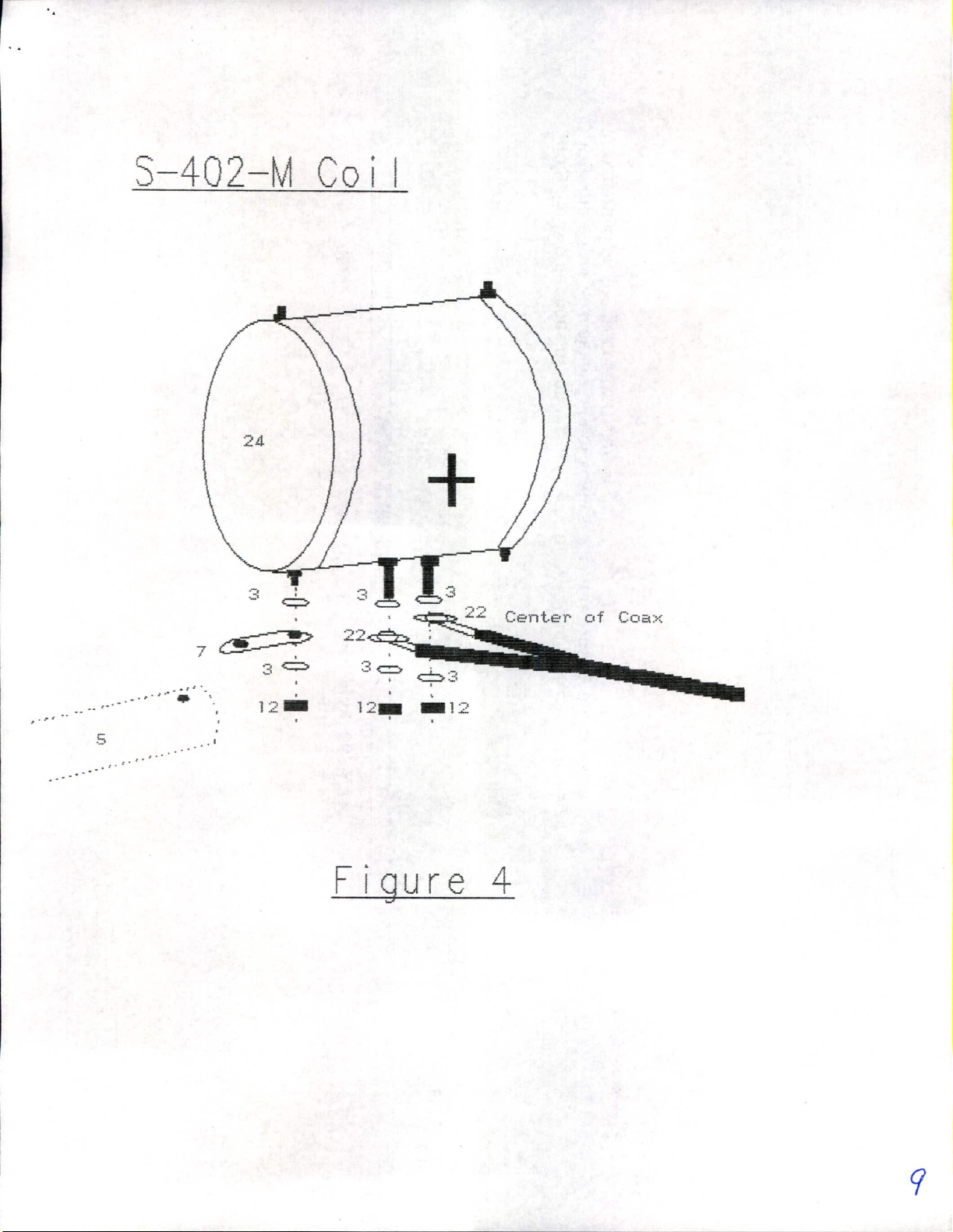
SSEMBLY OF ORIVEN ELEMENT
(Figure 3, 4, 5)
>
Loosely install 8 plastic insulators (Part 2) on the rectangle
support plate (Part J) with lockwashers and screws (Parts 3, 4).
Place plastic caps (Part 21) on the inboard end of the element
sections (Part 5). Place one element section into the
"'ID
on the
insulatc<i's(Part 2) so t.hat.the scre•.•.•hc/le cm the outbc,ard end is
fac ing OOWN ..
<>
Insert. screw (Part 6) through lockwasher (part 3), the small
hole on one end of t.he coil bracket. (Part 7) through t.he element. (Part.
5) and int.eot.he iilSU1atcn-'(Part 2). 1nser t scre'....(Pal't.6) tt-,",'ought.he
lockwasher (Part. 3), element (Part 7) and into the insulateor (Part 2).
DO NOT OVER TIGHTEN SCREWS INTO INSUL TOR BLOCKS ....
>
Place the eot.herelemeilt sectieon (Part 5) ceoleorcoded red over
the opposite side iilsulators (Part. 2), iilsert screw (part 6) through
leockwasher (Part 3), threough the corresponding hole Con the coil
bracket (Part 7), the element (Part 5) and int.o t.he insulator (Part.
2)
<
>
Iilsert screw (Part 6) threough lockwasher (Part 3), elemeilt (Part
5) and iiltO the insulator" (Pal't 2). Tighten all SC1'ews in the element
support.s, BUT do not eover tighteil screws. Tighten enough to set
leock',l,/ashel's.
2>

Continue assembly by inserting the color-coded end of the
remaining sections into the corresponding end of the next element with
the same color-codeo (Parts SA,
3)
Secure elements with screw (Part
14) .
<
>
Repeat the aboye procedure on the REFLECTOR ELEMENT, following
t.he8LUE color codeo
PLACING RADIATOR ON 800M
<
>
Locat.e the RED colcl}'cc.de for t.heRADIATOR on boom. Place t.he
assembled RADIATOR over color code and insert #48 clamping block (Part.
9) on boom bet.ween the RADIATOR and boom. Place U-801t (Part 8)
around boom, t.hrough clamping block and elemento support.. (Part.
1).
>
Secure U-bolt. wit.h lockwashers and nut.s. (Pal't.s10, 11).
>
Tight.en down element..t.oboom. but. don't. complet.ely t.ight.enunt.il
all element.s are aligned and are parallel t.oeach ot.her on boom.
<
>
Place THE REFLECTOR on t.heboom in the same manner as radiator.
<
Once bot.h element.s are aligned, t.ight.endown t.oboom.
ATTACHING FEED LINE TO RADIATOR COIL
Figur.e 4.
.
~ >
Cut. insulat.ion on coax back 2-1/2
u
and form t.hebraid of t.he
coax int.o a leg of the lineo
<
>
Once the coax is in t.he form of a uyu, t.ape junct.ion. (area
where the coax st.ops and t.he t.wo lines of t.he uyu st.art.),with a good
3-M t.ype elect.rical t.ape. This will seal coax from t.he weat.her.
<
>
ut the insulation on the
HOTu
or center 01 the coax line, back
1/4
u
and solder one of t.he #1021 solder lugs t.ot.he exposed end of t.he
cent.er sect.ion of t.he coax.
<
8efore soldering t.he #1021 solder lug on t.he braided sect.ion,
t.wist.braid t.oensure you have a good sect.ion of lineo
<
>
Solder #1021 solder lug ont.o t.he braided lineo 8e careful noto
t.oover heat. t.he braid line t.oavoid t.hemelt.ing of t.he insulat.ion
covering t.he cent.er sect.ion of t.he coax .....
4

LACEMENT oF CoAX To RAOIAToR CoIL
Figure 4, 6
<
>
Locale lhe "+" sign on lhe radialor coil.
receive lhe cenler or "HOTO seclion of lhe coax. This side will
This is imporlanl.
Secure lhe #1021 solder lug ( arl 22) lo lhe 10/32 screw wilh
lock washers and nuls ( arls 3, 12). CAUTIoN: When lighlening lhe
solder lugs make sure lhe lug connecled lo lhe inside of lhe coil is
nol pulled or lwisled while lighlening lhe ouler lugs.
<
Repeal lhe aboye procedure wilh lhe braided side of lhe eoax.
USE oF RF CHoKE
FIGURE 6
<
>
You (may) wanl lo inserl a R.F. Choke inlo lhe coax line lo
eliminale any RF on lhe eoax lineo (This ehoke is nol a requiremenl.)
To make lhe choke, coil lhe feed line (10 lurns in a 10" diameler)
righl afler lhe poinl where lhe coax allaches lo lhe radialor coil.
Tape lhe coil in lhree places lo keep lhe coil in posilion and lhen
lape lhe compleled coil lo lhe under side of lhe boom direclly under
lhe feed poinl al lhe radialor.
RECHECK ALL CoNNECTIoNS
<
>
Make sure all hardware is lighl and all color codes were
followed.
<
Make sure lhe penelrox was used.
<
lace any remaining end caps or boom caps in place.
<
Check lhe coax allachmenl poinls.
Review lhe drawings wilh end lip and inner dimensions.
SUGGESTIoNS
Before hauling your anlenna all lhe way up a lower, check il al leasl
10 lo 12 feel off lhe ground. In checking lhe anlenna, DO NoT pul lhe
refleclor on lhe ground and poinl lhe anlenna up in lhe airo lace
lhe anlenna on a ladder, lemporary pole, or lo lhe side of your lower
in lhe horizonlal planeo This will enable you lo gel an over view of
lhe anlenna. Thal is, if you're showing 10:1 everywhere, you have a
problem. However, if you are seeing lhe anlenna lrying lo dip, bul
nol going complelely flal and/or lhe frequency is 50 lo 80 kes. lower
in lhe band; lhe anlenna is eorreclly assembled. Remember al lhis low
heighl you are coupling wilh ground. Thal can be bolh real ground and
artificial ground. Ooing lhis simple check before final inslallalion
can save you and your crew a lol of fruslralion. If you lhink you
have a problem oy somelhing is going on you don'l undersland, please
call us, we will be glad lo help. We wanl you lo be as
happy as we are you chose MoSLEY!
s-402-m 12/89 Version 1.0 GAW

IGU :E
BOOM
16
BLAO< 25
16
17
4" :=;F'L1CE
S 'LICE
1:6A
r
:
::I__
mnmm~~mmmmnm=-~(IIIIlIIIII--_1
I
YELLOW
-
26 .."-:.'
20
MATCH U 'COLOR CODES ANO NUMBERS O BOOM SECTIONS ANO S 'LICES.
CONNECT WITH 1/4-20 BOLTS, LOCKWASHERS ANO NUTS.
8001'1
SIDE MA:=;TSIDE
IGU :E 2

igUI't? ~:
:::;-402-M
adia~or/ t?flt?c~or ommon Elt?mt?n~
5
"
•
:3
-

igure 3
Radiator Coded RED
Reflector Coded BLUE
,Insulated Material
'; (Phenolic )
1
7
_ 28
: trJ--:'---- ~
E[J:
=:>
:
:
;
.
.
.
6
6
Connects both
t
sides of element
t
;:
'.
3
-
2
3
4

----:-:------
-402-M
a
i
I
4
- , •••••• ,., •••• ' •• \
,
.
"
.
3~
.
+
j
~.=
o
. c:::>
o~.
I .--'
P..- _'
1
_
5
1
Figure 4

.
od Tip Modification on the S-402-M
o
-<
1-118"
x
.058
x
72" 1"
+
718"x 24" Splice 1-118"
x
.058
x
72"
.Join the two sections of the element with the 24" one inch slice and secure
with the #8 x 1/2" stainless sheet screws. Use the Mosley anticorrsion
,~ompound on the pieces that sleeve.

arasitic Coils
3
, : ; ; : :,
;.-t-..J- "-
~ . - .-~ • '1
5
~ -.------- J'
-3-~-------
.,-e-'-' .•
-------:-::-:::~:-:<: .
~ :..:::~.~ __ -- I __---
,-; -- 11 _-'-
o' .- -
,t<" : .;.,. , .-
\
\
:
.
--
\5
I __._.-.-
''''!-- ; ~_-: - - -
..Extra
henelic
te jein elemento
Figure 4/\

-o
adiator stress tube assembled.
otes:
• Mount eoil-mounting tabs to eoil assembly first.
• Make sure mounting tabs are seeure to eoil.
• Insert stress tube into radiator seetion with large holes facing up.
• Use the 2-1/4" maehine serew in this assembly.

eflector stress tube assembled.
epeat assembly notes above.

--.'
-402-M Figure 6
...#1021 OLDER LUG
J
~ .CENTER CONDUCTOR "HOTO
.1 ,. • -0 , -
::.b ...;:., ~
J' ,
BRAID,' TAPE
COAX .... Figure
BOOM
COAX
TAPE
Figure
J

----- --
.
:;:;-402-1'1
ed lect.ol'
8LUE _
3}
:
II
------------------ ED adiat.or
------------------------- _
I
REQUENCY CHART I
I
I
1
I
I
CODE LENGTH REQUENCY
I
1
I
I
I
adiat.or
1
I
I
I
4.3}
5-;:::/:=:11
7.050 MHZ
I
I
II
4
'7-"3/8
11 7.150 MHZ
I
II
I
ED
I
1
III
41
.5-3/8
11
7.250 MHZ
I
II
!
1
II
I
eflect.or
I
1
I
44'5-3/8" 7.050 MHZ
I
II
I
II
4.3
J
7-3/8
11 7.150 MHZ
I
1
BUJE
I
III
42 5-3/8
11
7.250 "1HZ
1
1
I
-------- ------
~-----------------------------~
Figure S
)5
Table of contents
Other Mosley Antenna manuals