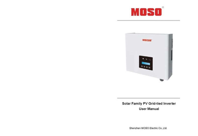
Moso SF1.6/2.2/3KTL-S User manual

Solar On-Grid Inverter
User Manual
Version 2.0 (EN)
SF 1.6/2.2/3 KTL-S
SF 4.2/4.6/5 KTL

All rights to the content of this manual are owned by MOSO Power Supply Technology Co.,
Ltd (hereinafter “MOSO”). No part of this document can be modified, distributed,
reproduced or published in any form or by any means without prior written permission
from MOSO.

Table of Contents
1 About This Manual
................................
1.1 Applicability
................................
1.2 Target Group
................................
1.3 Safety
................................
2 Introduction
................................
2.1 Overview
................................
2.2 Electrical Block Diagram
2.3 LED Display
................................
2.4 Terminal definition
................................
2.5 Dimension and Weight
................................
2.6 Terminal definition
................................
3 Functions ................................
................................
4 Operation Mode
................................
5 Installation
................................
5.1 Safety instruction
................................
5.2 Installation site selection
................................
5.3 Preparation
................................
5.4 Mount the Inverter
................................
5.5 Check Inverter Installation Status
5.6
Assembling the DC Connectors
6 Introduction
................................
6.1 System page
................................
6.2 Message page
................................
7 Communication
................................
7.1 Communication Interface
7.2 Communication
................................
8 Troubleshooting
................................
9 Decommissioning
................................
9.1 Dismantling
................................
9.2 Package
................................
9.3 Storage
................................
9.4 Disposal
................................
10 Technical Data
................................
10.1 Input(DC)
................................
10.2 Output(AC)
................................
10.3 Efficiency Safety and Protection
10.4 General Data
................................
11 Warranty ................................
................................
The Solar Family Series Inverter
1
Table of Contents
................................
................................................................
......................
................................
................................................................
..............................
................................
................................................................
..............................
................................
................................................................
................................
................................
................................................................
................................
................................
................................................................
................................
2.2 Electrical Block Diagram
................................................................
................................
................................
................................................................
..............................
................................
................................
................................
................................
................................
................................
................................
................................
................................
................................
................................
................................
................................
................................................................
........................
................................
................................................................
................................
................................
................................
................................
................................
................................
................................
................................
................................................................
...............................
................................
................................
................................
5.5 Check Inverter Installation Status
................................................................
............................
Assembling the DC Connectors
................................................................
...............................
................................
................................................................
................................
................................
................................................................
.............................
................................
................................................................
...........................
................................
................................................................
.........................
7.1 Communication Interface
Type ................................................................
................................
................................
................................
................................
................................
................................................................
.........................
................................
................................................................
......................
................................
................................................................
..............................
................................
................................................................
................................
................................
................................................................
................................
................................
................................................................
................................
................................
................................................................
........................
................................
................................................................
.........................
................................
................................
................................
10.3 Efficiency Safety and Protection
................................................................
............................
................................
................................................................
..........................
................................
................................
................................
The Solar Family Series Inverter
......................
2
..............................
2
..............................
2
................................
......... 2
................................
.. 6
................................
.... 6
................................
........... 8
..............................
9
................................
................... 10
................................
............. 10
................................
................... 12
................................
.... 14
........................
15
................................
.. 16
................................
..................... 16
................................
.......... 17
...............................
18
................................
................... 20
............................
21
...............................
21
................................
24
.............................
24
...........................
25
.........................
27
................................
27
................................
........................ 27
.........................
30
......................
32
..............................
32
................................
.... 32
................................
..... 32
................................
... 32
........................
33
.........................
33
................................
....................... 33
............................
34
..........................
34
................................
... 36

1 About This Manual
Improper use may result in potential electric shock hazards or burns. This manual mainly
describes the product information, guidelines for installation, operation and maintenance.
Please read these instructions
1.1 Applicability
This manual is applicable to the
SF1.6/2.2/3KTL-S
SF4.2/4.6/5KTL
1.2 Target Group
This manual is intended for:
Q
ualified personnel who are responsible
the inverter.
Inverter owners
who will have the ability to interact with the inverter.
1.3 Safety
1.3.1 Application
The SF1.6/2.2/3KTL-S
SF4.2/4.6/5
main function is to convert the DC current from PV strings into AC current and feed it into
grid.
A.PV Strings B. SF1.6~5
KTL
Figure 1 Principle of a PV Plant with
The Solar Family Series Inverter
2
Improper use may result in potential electric shock hazards or burns. This manual mainly
describes the product information, guidelines for installation, operation and maintenance.
Please read these instructions
carefully before use and keep them for future reference.
This manual is applicable to the
following inverter types.
ualified personnel who are responsible
for the installation and
commissioning of
who will have the ability to interact with the inverter.
SF4.2/4.6/5
KTL is a series of single phase on-
grid inverter, which
main function is to convert the DC current from PV strings into AC current and feed it into
KTL
C. AC Distribution Unit D. Low Voltage Grid
Figure 1 Principle of a PV Plant with
SF series inverter
The Solar Family Series Inverter
Improper use may result in potential electric shock hazards or burns. This manual mainly
describes the product information, guidelines for installation, operation and maintenance.
carefully before use and keep them for future reference.
commissioning of
grid inverter, which
main function is to convert the DC current from PV strings into AC current and feed it into

1.3.2
Safety Instructions
Safety symbols used in this manual, which highlight
safety information, are listed as follows:
CAUTION: Risk of electric shock.
Installation, debug and
qualified and accredited technicians.
Child, people with limited capacity or mental disorder is forbidden
to operate the inverter. People who lacks of operation experience
or common sense should operate the inverter under the guide o
professional.
Keep the child away from the inverter in case any injury happens.
CAUTION:
The temperature of the inverter bottom is high. Do not touch the
bottom while the inverter is operating to avoid risk of burns.
Warning!
Please do not
could cause serious damage to the inverter.
PV module used with inverter must have an IEC 61730 Class A
rating.
Warning!
•
Ensure that input DC voltage is less than
•
Over voltage may cause permanent damage to inverter or other
losses, which will not be included in warranty!
Warning!
•
Authorized service personnel must disconnect both AC and DC
power from the
or cleaning or working on any circuits connected to the
inverter.
Caution!
• The
photovoltaic array is exposed to light, it supplies a dc voltage to
the inverter
.
The Solar Family Series Inverter
3
Safety Instructions
Safety symbols used in this manual, which highlight
potential
safety risks and important
safety information, are listed as follows:
CAUTION: Risk of electric shock.
Installation, debug and
maintenance
should be operated by
qualified and accredited technicians.
Child, people with limited capacity or mental disorder is forbidden
to operate the inverter. People who lacks of operation experience
or common sense should operate the inverter under the guide o
professional.
Keep the child away from the inverter in case any injury happens.
The temperature of the inverter bottom is high. Do not touch the
bottom while the inverter is operating to avoid risk of burns.
Please do not
connect PV array positive or negative to ground, it
could cause serious damage to the inverter.
PV module used with inverter must have an IEC 61730 Class A
Ensure that input DC voltage is less than
m
ax. DC voltage.
Over voltage may cause permanent damage to inverter or other
losses, which will not be included in warranty!
Authorized service personnel must disconnect both AC and DC
power from the
SF series
inverter before attempting any maintenance
or cleaning or working on any circuits connected to the
photovoltaic array is exposed to light, it supplies a dc voltage to
the inverter
.
The Solar Family Series Inverter
safety risks and important
should be operated by
Child, people with limited capacity or mental disorder is forbidden
to operate the inverter. People who lacks of operation experience
or common sense should operate the inverter under the guide o
f
Keep the child away from the inverter in case any injury happens.
The temperature of the inverter bottom is high. Do not touch the
bottom while the inverter is operating to avoid risk of burns.
connect PV array positive or negative to ground, it
PV module used with inverter must have an IEC 61730 Class A
ax. DC voltage.
Over voltage may cause permanent damage to inverter or other
Authorized service personnel must disconnect both AC and DC
inverter before attempting any maintenance
or cleaning or working on any circuits connected to the
SF series
photovoltaic array is exposed to light, it supplies a dc voltage to

1.3.3 Safety Symbols
·
Symbols on the inverter
Symbol
Danger of
high voltage
R
esidual voltage will vanish in 5 minutes after the inverter
disconnected.
Open the front cover of the inverter at least 5 minutes after
disconnecting.
Beware of hot surface
The
inverter can get hot during operation.
bottom or radiator during operation. Install the inverter where is not
accessible
Risk of electric shock!
Do not disassemble the cover of the inverter.
personnel
Danger of
electricity shock !
When exposed to sunlight, the PV array generates
Users should read this manual before installation and operate it
according to this manual.
Indicates
caution followed by important instructions
Equipment grounding conductor
AC voltage
.
You can operate the interface by tapping on it
•
Tapping once: The background illumination switches on.
•
Tapping again: Updating information.
The Solar Family Series Inverter
4
Symbols on the inverter
Description
high voltage
!
esidual voltage will vanish in 5 minutes after the inverter
disconnected.
Open the front cover of the inverter at least 5 minutes after
disconnecting.
Beware of hot surface
!
inverter can get hot during operation.
Avoid touching the
bottom or radiator during operation. Install the inverter where is not
accessible
for children.
Risk of electric shock!
Do not disassemble the cover of the inverter.
Only authorized
personnel
can be allowed to inspect or maintain
the inverter
electricity shock !
When exposed to sunlight, the PV array generates
Users should read this manual before installation and operate it
according to this manual.
caution followed by important instructions
.
Equipment grounding conductor
.
.
You can operate the interface by tapping on it
.
Tapping once: The background illumination switches on.
Tapping again: Updating information.
The Solar Family Series Inverter
esidual voltage will vanish in 5 minutes after the inverter
Open the front cover of the inverter at least 5 minutes after
Avoid touching the
bottom or radiator during operation. Install the inverter where is not
Only authorized
the inverter
.
direct voltage.
Users should read this manual before installation and operate it
Tapping once: The background illumination switches on.

You can
operate the interface by
For more information on
‘
LCD display
Recovery and recycling.
·
Symbols on the type label
Symbol
CE mark.
•
The inverter complies with the
guidelines.
TUV mark.
•
The inverter complies with the requirements of the applicable TUV
guidelines.
CQC mark.
•
The inverter complies with the requirements of the applicable
guidelines.
The Solar Family Series Inverter
5
operate the interface by
pressing buttons.
For more information on
operating the buttons, refer to
Section
LCD display
’.
Recovery and recycling.
Symbols on the type label
Explanation
The inverter complies with the
requirements of the applicable CE
The inverter complies with the requirements of the applicable TUV
The inverter complies with the requirements of the applicable
The Solar Family Series Inverter
Section
7.2
requirements of the applicable CE
The inverter complies with the requirements of the applicable TUV
The inverter complies with the requirements of the applicable
CQC

2 Introduction
2.1 Overview
Figure 2
Figure 3
1. Bracket
2. Heat sink
1
2
The Solar Family Series Inverter
6
Stereogram - Front for SF1.6/2.2/3KTL-S
Stereogram – Back for SF1.6/2.2/3KTL-S
The Solar Family Series Inverter

Figure
4
Figure 5
1. Bracket
2. Heat sink
1
2
The Solar Family Series Inverter
7
4
Stereogram - Front for SF4.2/4.6/5KTL
Stereogram – Back for SF4.2/4.6/5KTL
The Solar Family Series Inverter

This manual is applicable to the following inverter types.
SF1.6KTL-S
SF2.2KTL-S
SF3KTL-S
SF4.2KTL
SF4.6KTL
SF5KTL
Model name identifying
SF5KTL
1 2 3
Model description
No. Meaning
1 Series name
2 Power capacity
3 Topology mark
2.2 Electrical Block Diagram
● Electrical block diagram
Input
EMI
Filter
MPPT
1
+
-
Figure 6
Electrical block diagram
Input
EMI
Filter
MPPT1
MPPT2
+
-
+
-
Figure 7
Electrical block diagram
The Solar Family Series Inverter
8
This manual is applicable to the following inverter types.
Description
SF: single phase string on-
grid inverter
5K: power capacity is 5kW
TL: Transformerless
2.2 Electrical Block Diagram
1
Inverter
Circuit
AC
Filter
Output
EMI
Filter
Output isolation
relay
Electrical block diagram
of SF1.6/2.2/3KTL
Inverter
Circuit
AC
Filter
Output
EMI
Filter
Output isolation
relay
Electrical block diagram
of SF4.2/4.6/5KTL
The Solar Family Series Inverter
grid inverter
PE
L
N
PE
L
N

2.3 LED Display
Three LED indicators
on the panel
LED 1(Green)
LED 2(Green)
LED 3(Red)
Normally, a
fter starting up, DC/DC LED and DC/AC LED will be lighted
inverter is feeding
power to the grid.
The Solar Family Series Inverter
9
on the panel
as follows:
Figure 8
Figure 9
Off The DC/DC circuit is off.
Blinking The DC/DC circuit starts.
On
The DC/DC circuit is working normally.
Off The DC/AC circuit is off.
Blinking The DC/AC circuit starts.
On
The DC/AC Circuit is working normally.
Off No error occurs.
On The inverter is in fault status.
fter starting up, DC/DC LED and DC/AC LED will be lighted
which indicates
power to the grid.
The Solar Family Series Inverter
The DC/DC circuit is working normally.
The DC/AC Circuit is working normally.
which indicates
that the

2.4
Terminal definition
Figure 10
Figure 11
序号 名称
1
PV Terminals
2 Degassing
3 WiFi/GPRS
4
AC Terminals
5 LCD Display
2.5
Dimension and Weight
● Dimension
The Solar Family Series Inverter
10
Terminal definition
Figure 10
:SF1.6KTL/SF2.2KTL/SF3KTL-S Terminals
Figure 11
:SF4.2KTL/SF4.6KTL/SF5KTL Terminals
描述
PV Terminals
SF1.6/2.2/3KTL-S owns one MPPT
with a pair of DC
terminals.
SF4.2/4.6/5KTL owns two independent
MPPT
PV1and PV2,
each of which with a pair of DC
terminals.
Release press from internal.
Terminals connect the WiFi module or RS485 module.
AC Terminals
AC output
The display shows the status information (e.g.
status, power, input voltage) as well as errors and
disturbances.
Dimension and Weight
RS485
The Solar Family Series Inverter
with a pair of DC
MPPT
,
each of which with a pair of DC
Terminals connect the WiFi module or RS485 module.
The display shows the status information (e.g.
working
status, power, input voltage) as well as errors and

Figure
12
Figure
●Weight
Model
SF
1.
6
K
TL
SF
Weight [kg]
8
The Solar Family Series Inverter
11
12
SF1.6KTL-S/ SF2.2KTL-S/ SF3KTL-S
Figure
13 SF4.2KTL/ SF4.6KTL/SF5KTL
Table 1
SF
2.2K
TL
SF
3K
TL
SF
4.2K
TL
SF
4.6K
TL
8 8 11 11
The Solar Family Series Inverter
TL
SF5KTL
11

2.6 Terminal
definition
The Solar Family is shipped with the following items:
Item
A
Solar Inverter
B
Mounting Frame
C
Mounting Screws
D P
V
E M4*8
Mounting Screws
F
A
D
G
逆变器
用户手册
The Solar Family Series Inverter
12
definition
Table 2
The Solar Family is shipped with the following items:
Figure 14
Name
Quantity
Solar Inverter
1
Mounting Frame
1
Mounting Screws
4
V
Terminals 4
Mounting Screws
4
Manual 1
B
C
E
F
The Solar Family Series Inverter
Quantity

Nameplate: take SF5KTL for example
Figure 15
The Solar Family Series Inverter
13
Nameplate: take SF5KTL for example
The Solar Family Series Inverter

3 Functions
The basic functions of the inverter are as follows.
【Conversion function】
The inverter converts DC power from the PV array into grid
feeds it into the utility grid.
【Data storage】
Inverter logs essential data including running information and error records.
【Parameter configuration
】
Inverter provides various parameter configurations for optimal operation.
【Communication
interface
You can choose the RS485 terminal for connecting a communication module to the PV
system, such as Wi-
Fi module.
【Protective function】
The protective functions are integrated in the inverter, including short circuit protection,
grounding
insulation resistance surveillance, residual current protection, anti
protection, DC overvoltage/over
The Solar Family Series Inverter
14
The basic functions of the inverter are as follows.
The inverter converts DC power from the PV array into grid
-
compliant AC
Inverter logs essential data including running information and error records.
】
Inverter provides various parameter configurations for optimal operation.
interface
】
You can choose the RS485 terminal for connecting a communication module to the PV
Fi module.
The protective functions are integrated in the inverter, including short circuit protection,
insulation resistance surveillance, residual current protection, anti
protection, DC overvoltage/over
-current protection, etc.
The Solar Family Series Inverter
compliant AC
power and
Inverter logs essential data including running information and error records.
You can choose the RS485 terminal for connecting a communication module to the PV
The protective functions are integrated in the inverter, including short circuit protection,
insulation resistance surveillance, residual current protection, anti
-islanding

4 Operation Mode
NOTICE!
The inverter output power decrease is usual in the condition of thermal
protection, but if it occurs frequently, you need to check the heat sink or
consider putting the inverter in the place where have better air flow, and if
output power decreases caused by electrical problem, please ask for
professional supports.
The Solar Family Series Inverter
15
Figure 16
The inverter output power decrease is usual in the condition of thermal
protection, but if it occurs frequently, you need to check the heat sink or
consider putting the inverter in the place where have better air flow, and if
output power decreases caused by electrical problem, please ask for
The Solar Family Series Inverter
The inverter output power decrease is usual in the condition of thermal
protection, but if it occurs frequently, you need to check the heat sink or
consider putting the inverter in the place where have better air flow, and if
output power decreases caused by electrical problem, please ask for

5 Installation
5.1 Safety instruction
DANGER!
Improper
installation may cause fire or
• Do not install
the inverter on flammable
materials.
•
Make sure there is no electrical connection before installation.
CAUTION!
Improper
carry may cause injury.
•
Avoid getting injury by improper carry.
• Select a
firm
•
Use proper tools for installation.
•
At least two people are suggested to coordinate for the installation.
CAUTION!
HOT!
• Some
parts of the inverter will be hot during
operation.
·Open the package
Check the inverter and accessories according to the pack list. If the inverter is damaged
or any accessory missing, please contact the local distributor.
The Solar Family Series Inverter
16
installation may cause fire or
explosion.
the inverter on flammable
and explosive
construction
Make sure there is no electrical connection before installation.
carry may cause injury.
Avoid getting injury by improper carry.
firm
mounting surface.
Use proper tools for installation.
At least two people are suggested to coordinate for the installation.
parts of the inverter will be hot during
Check the inverter and accessories according to the pack list. If the inverter is damaged
or any accessory missing, please contact the local distributor.
The Solar Family Series Inverter
construction
Make sure there is no electrical connection before installation.
At least two people are suggested to coordinate for the installation.
Check the inverter and accessories according to the pack list. If the inverter is damaged

5.2
Installation site selection
The following must be considered when selecting the location for an inverter:
The mounting and installation method must be appropriate for the inverter
and dimensions.
Mount on a solid surface.
The environment
temperature
inverter(-25℃ to +60℃
; derating between 45
Do not install the inverter at altitude of above 2000m, otherwise the inverter will
derate.
Do not install the inverter in corrosive gas or
Do not install the inverter in an area with risk of flood or frozen.
Do not install the inverter in confined space or high humidity.
Do not expose the inverter to strong cold air, steam, fog or water.
Do not install the inverter closed
The inverter must be installed vertically or with a backward tilt of no more than 15
degrees.
The connection area must face downwards.
•
Mount the inverter at eye level. Given the weight of the device, this will facilitate
disassembly if
service work is necessary.
•
The ambient temperature should be
performance.
•
Do not expose the inverter to direc
thus power reduction.
•
In living areas, do not mount the unit on plasterboard walls or similar in order to avoid
audible
vibrations. When in use, the inverter emits noises which may be perceived as a
nuisance in a living area.
•
Observe the recommended clearances to walls
shown in the
diagram. This ensures adequate heat
the optional DC switch.
•
If multiple inverters are mounted in
the clearances
between the inverters and ensure an adequate
The Solar Family Series Inverter
17
Installation site selection
The following must be considered when selecting the location for an inverter:
The mounting and installation method must be appropriate for the inverter
Mount on a solid surface.
temperature
should not exceed the working temperature of the
; derating between 45
℃ to 60℃ )
Do not install the inverter at altitude of above 2000m, otherwise the inverter will
Do not install the inverter in corrosive gas or
dip in liquid
such as sea water.
Do not install the inverter in an area with risk of flood or frozen.
Do not install the inverter in confined space or high humidity.
Do not expose the inverter to strong cold air, steam, fog or water.
Do not install the inverter closed
to TV cable or antenna cable.
The inverter must be installed vertically or with a backward tilt of no more than 15
The connection area must face downwards.
Figure 17
Mount the inverter at eye level. Given the weight of the device, this will facilitate
service work is necessary.
The ambient temperature should be
lower than 40°C to
achieve optimal
Do not expose the inverter to direc
t sunlight
as this can cause excessive heating and
In living areas, do not mount the unit on plasterboard walls or similar in order to avoid
vibrations. When in use, the inverter emits noises which may be perceived as a
Observe the recommended clearances to walls
,other inverters or other objects, as
diagram. This ensures adequate heat
sink
and sufficient room to operate
If multiple inverters are mounted in
areas with high
ambient temperatures, increase
between the inverters and ensure an adequate
fresh-
air supply. This will
The Solar Family Series Inverter
The following must be considered when selecting the location for an inverter:
The mounting and installation method must be appropriate for the inverter
’s weight
should not exceed the working temperature of the
Do not install the inverter at altitude of above 2000m, otherwise the inverter will
such as sea water.
The inverter must be installed vertically or with a backward tilt of no more than 15
Mount the inverter at eye level. Given the weight of the device, this will facilitate
achieve optimal
as this can cause excessive heating and
In living areas, do not mount the unit on plasterboard walls or similar in order to avoid
vibrations. When in use, the inverter emits noises which may be perceived as a
,other inverters or other objects, as
and sufficient room to operate
ambient temperatures, increase
air supply. This will

prevent a reduction in
inverter power as a result of excessively high
(details on temperature derating can
5.3 Preparation
Tools for installation are as follows.
a)
Mount the bracket
Adequate space
for cooling is required
Using the mounting bracket
as a template, drill 3 holes as illustrated in image
The Solar Family Series Inverter
18
inverter power as a result of excessively high
temperatures
(details on temperature derating can
b
e found in the Technical Information
Tools for installation are as follows.
Figure 18
Mount the bracket
for cooling is required
. Keep
at least 20cm space above and below the inverter.
Figure 19
as a template, drill 3 holes as illustrated in image
The Solar Family Series Inverter
temperatures
e found in the Technical Information
).
at least 20cm space above and below the inverter.
This manual suits for next models
1
Table of contents
Other Moso Inverter manuals
Popular Inverter manuals by other brands

IRONRIDGE
IRONRIDGE BX SYSTEM installation manual

ring
ring PowerSourcePure Series instruction manual

Tracon
Tracon INV230ACB user manual

Ventev
Ventev VS01-12-0010-018 Installation, operation and maintenance guide

ABB
ABB LMIU1500 instruction manual

Xylem
Xylem CentriPro AQUAVAR CPC4 FD Series Supplement manual

Mitsubishi Electric
Mitsubishi Electric FR-A872-P instruction manual

Analytic Systems
Analytic Systems IPS600 SERIES Installation & operation manual

Inverter Drive
Inverter Drive CFW-08 Easy start guide

Huawei
Huawei PowerCube 5000 installation guide

JED
JED 103 Installation and operation manual

WEG
WEG AG10 Series Installation, operation and maintenance manual