Moso SF8KTL User manual

Solar Inverter SF8KTL


CONTENTS
1. INTRODUCTION............................................................................................................................................................ 1
1.1How to use this manual.........................................................................................................................................1
1.2Validity.....................................................................................................................................................................1
1.3Target Group.............................................................................................................................................................1
2. SAFETY........................................................................................................................................................................... 2
2.1 Safety Instructions.............................................................................................................................................2
2.2 Glossary Symbol.....................................................................................................................................................2
3. PRODUCT INTRODUCTION....................................................................................................................................... 3
3.1 Overview.................................................................................................................................................................. 3
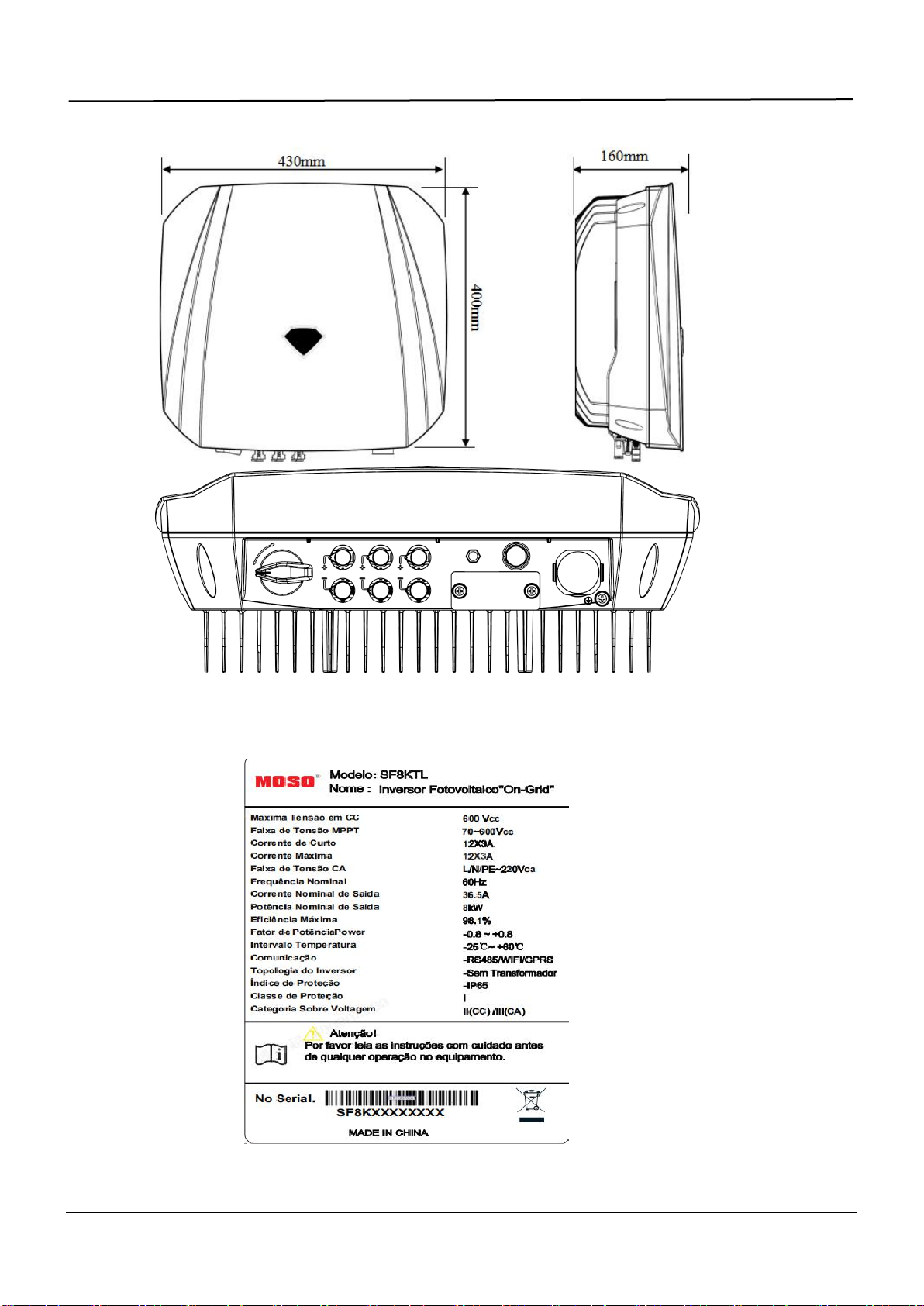
3.2 Type Label...............................................................................................................................................................3
4. INSTALLATION.............................................................................................................................................................. 3
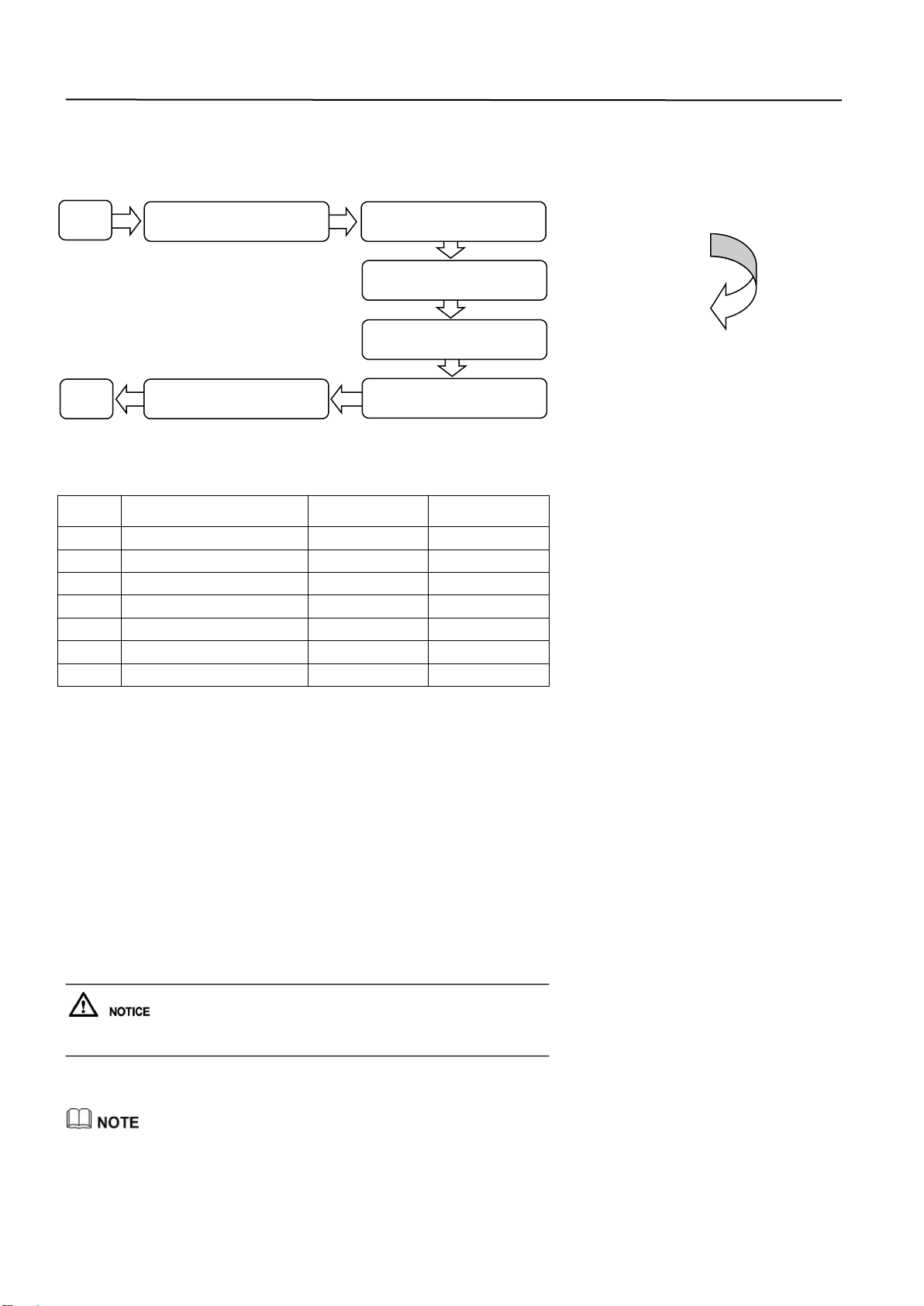
4.1 Installation Process...........................................................................................................................................4
4.2 Pre-installation check.......................................................................................................................................4
4.3 Choose an installation location.....................................................................................................................4
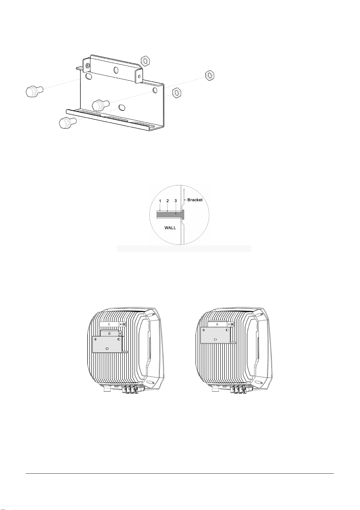
4.4Installing the SF series.....................................................................................................................................4
5.ELECTRICAL CONNECTION....................................................................................................................................... 6
5.1 Electrical connection process.........................................................................................................................6
5.2 Connecting PGND Cables(PE)...........................................................................................................................6
5.3 Connecting AC Output Power Cables.................................................................................................................6
5.4 Connecting DC Input Power Cables...................................................................................................................8
5.5 Disconnect the electrical connections.........................................................................................................9
6. SYSTEM OPERATION................................................................................................................................................10
6.1 Operating mode.....................................................................................................................................................10
6.2 Powering on the SF series...............................................................................................................................10
A.1 DC Input................................................................................................................................................................. 10
A.2 AC Output..............................................................................................................................................................11
A.3 General Data.......................................................................................................................................................... 11


1
1. INTRODUCTION
1.1How to use this manual
In order to better use this manual, please understand the information of product model, Intended audience and symbol
conventions that it oriented and other information.
1.2Validity
This manual describes the assembly, installation, commissioning and maintenance of the following inverters:
SF6KTL
SF7KTL
SF8KTL
1.3Target Group
This manual is for qualified personnel. Qualified personnel have received training and have demonstrated skills and knowledge
in the construction and operation of this device. Qualified Personnel are trained to deal with the dangers and hazards involved in
installing electric devices.

2
2. SAFETY
Please read safety precautions in this manual carefully, if ignored, could result in serious injury or death.
2.1 Safety Instructions
When using the product, please do remember the below information to avoid the fire, lightning or other personal injury:
Ensure that input DC voltage is less than Max. DC input voltage.
Over voltage may cause permanent damage to inverter or other losses, which will not be include in warranty!
This chapter contains important safety and operating instructions.
Read and keep this operation guide for future reference.
Authorized service personnel must disconnect both AC and DC power from the SF series inverter before attempting any
maintenance or cleaning or working on any circuits connected to the SF series inverter.
2.2 Glossary Symbol
This section gives a glossary of all the symbols shown on the inverter and the type label.
Table 2-1 Symbols on the inverter
Symbol
Meaning
Danger to life due to high voltages in the inverter
There would be residual voltage in the inverter. Operation after 5 minutes.
Beware of hot surface
The inverter may become hot during operation. Avoid any contact to the
surface during operation.
Danger of high voltages
Danger to life due to high voltages in the inverter!
Requests the user to consult the manual.
Warning signs
Pay attention to the safety of inverter operation.
Grounding mark
The inverter is connected with the ground to achieve the purpose of groun
ding protection

3
3. PRODUCT INTRODUCTION
3.1 Overview
SF8TL series
3.2 Type Label
The type labels provide a unique identification of the inverter (The type of product, Device-specific characteristics, Certificates
and approvals). The type labels are on the right-hand side of the enclosure.

4
4. INSTALLATION
4.1 Installation Process
Installation Process of SF series,as shown in Figure 4-1。
Figure 4-1 Installation Flow chart
4.2 Pre-installation check
Table 4-1 Deliverables description
Number
Explanation
Quantity
(SF6KTL Series)
Quantity
(SF8TL Series)
1
SF series Inverter
1
1
2
Bracket
1
1
3
Expansion bolts and screws
4
4
4
DC input connector of negative
2
3
5
AC output connector
1
1
6
DC input connector of positive
2
3
7
User manual
1
1
4.3 Choose an installation location
The installation method and mounting location must be suitable for the weight and dimensions of the inverter. Select a wall or
solid vertical surface which is able to support the PV inverter.
Mount on a solid surface, the mounting location must be accessible at all times.
Vertical installation or tilted backwards by max. 15°.
The connection area must point downwards.
Do not install horizontally.
To ensure good heat dissipation and reserve enough space for installing the SF series, the SF series is at least 30cm, 50 cm,
100cm, and 50cm away from objects on its both sides, top, bottom, and front respectively, as shown in Figure 4-3.
Figure 4-3Minimuminstallationclearance
When installing multiple SF series Inverters in high temperature areas, please increase the space properly as needed to make sure that there is
enough space for heat dissipation.
4.4Installing the SF series
If the installation locations near the ground ,first connect the PGND cable to the ground before installing the Inverter on the wall.
Step 1Install the bracket
1.Determine the position for drilling holes, level hole positions, and then mark the hole positions by using a marker, as shown in
Figure 4-4
End
Star
t
Installation check
Preparing Installation Tools
Choose an installation
location
Moving inverter
Installation the bracket
Installation the inverter

5
Figure 4-4 Hole positionsanddimensions(Unit :mm)
Drill holes by using a hammer drill and install expansion bolts.
.
2. Align the bracket with hole positions, insert expansion bolts into the holes, and tighten the expansion bolts to a torque of 30
N.m using a torque wrench, as shown in Figure 4-5.
Figure 4-5Securinga bracket
1、The hole in the wall 2、Plastic screw socket 3、Tapping screw
Step 2Install the SF series
1. Use one hand to hold the handle at the bottom of the SF series and use the other hand to hold the handle close to the top of
the SF series and then stand the SF series. Two peoples are required to install the SF series.
1.Mount the SFseries on the bracket and keep them aligned with each other, as shown in Figure 4-6.
Figure 4-6 Mounting the SF series on the bracket (left view)

6
5.ELECTRICAL CONNECTION
5.1 Electrical connection process
Electrical connection process of SF series as shown in Figure 5-1。
Figure 5-1 Electrical connection flowchart
5.2 Connecting PGND Cables(PE)
Good grounding for the SF series can help resist the impact of the surge voltage and improve the EMI performance. First
connect the PGND cable before connecting the AC power cable, DC power cable, and communication cable.
For the system with one SF series, connect the PGND cable to the ground. For the system with multiple SF series ,connect the
PGND cables of all SF series to a ground bar.
If the installation location is near the ground ,first connect the PGND cable to the ground before installing the SF series on the
wall.
Step 1 Remove the insulation layer with an appropriate length using a wire stripper. Insert the exposed core wires into the OT
terminal and crimp them by using a crimping tool, as shown in Figure 5-2.
Figure 5-2 Preparing a ground cable
Step 2Install the crimped OT terminal, flat washer, and spring washer on the M6 welded stud, and tighten the nut to a torque of5
N.m using a socket wrench.
Toenhancetheanti-corrosionperformanceofthegroundterminals,applysilicagel on the mafter connecting the ground cable.
5.3 Connecting AC Output Power Cables
Figure 5-3 AC connector diagram
1. Adapter 2. .Sleeve 3. Cable Gland 4. AC output connector
Step 1 Remove the cable gland and the adapter from the AC output connector.
Step 2 Remove the insulation layer of the AC output cable of an appropriate length using a wire stripper.
1. Strip the outer jacket of AC output cable by 55mm.
2. CutthecorewiresofthecablesexcludingthePGNDcableby2.5mm. That is, the core wire of the PGND cable should be 2.5
mm longer than that of other four cables.
3. Strip the insulation layer of each core wires by 12mm.
End
Connecting DC Input Cables
Connecting AC output Cables
Connecting PGND Cables
(PE)
Start

7
Figure 5-4 Connecting an AC output power cable (1) (unit: mm)
Step 3 Insert AC output cable (L, N, PE) into the cable gland and the adapter, as shown in Figure 5-6.
Figure 5-5 Connecting an AC output power cable (2)
Step 4 Loosen the screws inside the coupling nut holes using a screwdriver, insert the core wires into
corresponding holes, and tighten the screws, as shown in Figure 5-6.
Tighten the screws to a torque of 0.7 N.m.
Figure 5-6 Connecting an AC output power cable (3)
Connect L to the hole L. Connect N to the hole N. Connect PE to
the hole PE .
Step 5 Check that all core wires are properly connected.
Step 6 Secure the adapter to the coupling nut.Tighten the adapter to a torque of 1~2 N.m.
Step 7 Secure the cable gland to the adapter, as shown in Figure
5-8.Tighten the cable gland to a torque of 5 N.m (You need to use some tool to achieve this torque).
Figure 5-7 Connecting an AC output power cable (4)
Step 8 Connect the AC output connector to the bayonet coupling of the AC output wiring terminal on the SF
series and rotate it clockwise until you hear a "click" sound.
Because no sufficient space is available on the right of the AC terminal, tighten the terminal using the left hand.

8
5.4 Connecting DC Input Power Cables
Before connecting the DC input cable, please make sure that the Inverter “DC SWITCH” in the “OFF” status, otherwise, the high voltage can
bring about life threatening.
Table 5-2 Recommended DC input cable specifications
Conductor cross-section(mm2)
Cable diameter range(mm)
Range
Recommended Value
2.5~4.0
4.0
4.5~7.8
DC input connector include positive connector and negative connector, as shown in figure 5-8.
Figure 5-8 Positive connector and Negative connector
Step 1Remove cable glands from the positive and negative connectors. Then ,Remove the insulation layer with an appropriate
length from the positive and negative power cables by using a wire stripper as show in Figure 5-9.
Figure 5-9ConnectingDCinputpowercables(1)
1. Positive power cable 2. Negative power cable
Step 2Insert the positive and negative power cables into corresponding cable glands.
Step 3Insert the stripped positive and negative power cables into the positive and negative metal terminals respectively and
crimp them using a clamping tool. Ensure that the cables are crimped until they cannot be pulled out by force less than 400 N,
as shown in Figure 5-10.
Figure 5-10 Connecting DC input power cables(2)
1. Positive power cable 2. Negative power cable
Step 4Insert crimped power cables into corresponding housings until you hear a "click" sound. The power cables snap into
place.
Step 5Reinstall cable glands on positive and negative connectors and rotate them against the insulation covers.
Before performing step 6, the DC switch is OFF.
Step 6Insert the positive and negative connectors into corresponding DC input terminals of the SF series until you hear a "click"
sound, as shown in Figure 5-11.
Figure 5-11Connecting DC input power cables(3)

9
1. Bayonet
5.5 Disconnect the electrical connections
Step 1 Disconnect the circuit breaker between the inverter and the grid.
Step 2 Ensure that the DC SWITCH is OFF.
Step 3 Disconnect the RS485 communication cable.
Step 4 Disconnect the DC input cable.
Step 5 Disconnect the AC input cable.
Step 6 Disconnect the ground cable.

10
6. SYSTEM OPERATION
6.1 Operating mode
SF series has three working mode: standby mode, operating mode, off mode.
6.2 Powering on the SF series
After ensure that electrical connections have been completed correctly, run the operation of power-on, then turn on the inverter.
Step 1Check that the SF series is installed on the wall correctly and securely.
For details, see 4.3Installing the SF series.
Step 2Check that all AC output power cables are properly connected.
For details, see 5.3ConnectingACOutputPowerCables.
Step 3Check that all DC input power cables are properly connected.
For details, see 5.4 Connecting DC Input Power Cables
Step 4Ensure that unused DC input terminals are sealed.
Step 5Switch on the AC circuit breaker between the SF series and the power grid.
Step 6Ensure that the DC SWITCH at the bottom of the SF series is ON.
LED
Message
Status
Definition
LED1
Communication
Status
Red
Grid fault
Green
OK
LED2
Status Grid
Red
Communication failure
Green
OK
LED3
Alarm Status
Red
Inverter fault
Green
OK
The monitoring panel can be activated only after power is supplied to the DC side.
7. Specification
A.1 DC Input
Model
SF6KTL
SF7TL
SF8TL
Max DC Power
6600W
7700W
8800W
Max Input Current
12A
12A
12A
Max DC Voltage
600V
600V
600V
Number of MPPT Trackers
2
3
3
MPPT Voltage Range
70-600V
70-600V
70-600V

11
A.2 AC Output
Model
SF6KTL
SF7TL
SF8TL
Rated Output Power
6000W
7000W
8000W
Max AC Output Power
6600W
7700W
8000W
Max Output Current
26A
33A
35A
Output Voltage
220/230/240 VAC
220/230/240 VAC
220/230/240 VAC
Grid Frequency
50/60Hz
50/60Hz
50/60Hz
Power Factor(cosΦ)
0.8Lead…0.8Lag
0.8Lead…0.8Lag
0.8Lead…0.8Lag
Harmonics
<3%
<3%
<3%
A.3 General Data
Model
SF6KTL
SF7TL
SF8TL
Dimension(W/H/D)
[mm]
430/400/160
430/400/160
430/400/160
Weight
16kg
18kg
18kg
Cooling Method
Natural Cooling
Natural Cooling
Natural Cooling
Operating Temperature
Range
-25℃~60℃
-25℃~60℃
-25℃~60℃
Humidity
0%~95%
(Non-Condensing)
0%~95%
(Non-Condensing)
0%~95%
(Non-Condensing)
IP Grade
IP65
IP65
IP65
Topology
No Transformer
No Transformer
No Transformer
Communication Interface
WIFI(Opt.)/GPRS(Opt.)
Warranty Period
5 Years
5 Years
5 Years
This manual suits for next models
2
Table of contents
Other Moso Inverter manuals