DMX
CHANNEL
1
2
dp 1.1 dp 2.1 dp 1.1 dp 2.1 dp 3.2
DMX
CHANNEL
1
2
3
4
DMX
CHANNEL
1
2
3
4
5
6
dp 1.1 dp 2.1 dp 4.3 dp 5.3
Select menu , press “ENTER” the display will flash.
Press “UP/DOWN” to choose the decoding mode. Press “BACK” to confirm.
DMX Address is 001, CH02DMX Address is 001, CH01
DMX Address is 001, CH03
all output dim
not in use
all output dim
all output ne dim
output 1,3 dim
output 2,4,5 dim
output 1,3 dim
output 1,3 ne dim
output 2,4,5 dim
output 2,4,5 ne dim
output 1,3 dim
output 2,4,5 dim
all output dim
output 1 dim
output 2 dim
output 3,4,5 dim
output 1 dim
output 1 ne dim
output 2 dim
output 2 ne dim
output 3,4,5 dim
output 3,4,5 ne dim
output 1 dim
output 2 dim
output 3,4,5 dim
master dim
all output dim
output 1 dim
output 2 dim
output 3,4,5 dim
master dim
strobe FX
TRUE 16-BIT TRUE 16-BIT
TRUE 16-BIT
FACTORY DEFAULTFACTORY DEFAULT
FACTORY DEFAULT
6. Decoding Mode
DMX Value
>1
<1
1.0
1.5
2.5
3.5 6.5
0.90.9
0.8
Output Brightness
*Gamma adjusts the dimming curve of
the unit so you can have an extremely
high resolution low end or an extremely
high resolution high end.
Select menu , press “ENTER” the display will flash.
Press “UP/DOWN” to choose 0.1 to 9.9. Press “BACK” to confirm.
5. Gamma Curve Value
20 = 20KHz
25 = 25KHz
35 = 35KHz
14 = 14KHz
16 = 16KHz
18 = 18KHz
09 = 9KHz
10 = 10KHz
12 = 12kHz
06 = 6KHz
07 = 7KHz
08 = 8KHz
03 = 3KHz
04 = 4KHz
05 = 5KHz
00 = 500Hz
01 = 1KHz
02 = 2KHz
Select menu , press “ENTER” the display will flash. Press “UP/DOWN”
to choose from 00 to 35. Press “BACK” to confirm. Default @ 10khz.
4. PWM Frequency
Select menu , press “ENTER” the display will flash. Press “UP/DOWN”
to choose 8bit or 16bit. Press “BACK” to confirm.
3. Resolution
Example: DMX address is set to 001.
CH01 : DMX Footprint = 1 (DMX address for all channels is 001)
CH02 : DMX Footprint = 2 (DMX address 001 for channels 1&3. DMX address 002 for channels 2, 4&5)
CH03 : DMX Footprint = 3 (DMX address 001&002 for channels 1, 2. DMX address 003 for channels 3, 4&5)
CH04 : DMX Footprint = 4 (DMX address 001&002&003 for channels 1, 2&3. DMX address 004 for channels 4&5)
CH05 : DMX Footprint = 5 (DMX address 001,002,003,004&005 for channels 1, 2, 3, 4 ,5 respectively)
Select menu , press “ENTER” the display will flash. Press “UP/DOWN”
and set the DMX channel quantity. Press “BACK” to confirm.
2. Set Channel Quantity
To set the DMX address select menu , press “ENTER” the display will flash.
Press “UP/DOWN”to set the DMX address. Press “BACK” to confirm.
1. Set DMX Address
P.XXX
XX to XX
B XX
S XX
R N 2
1
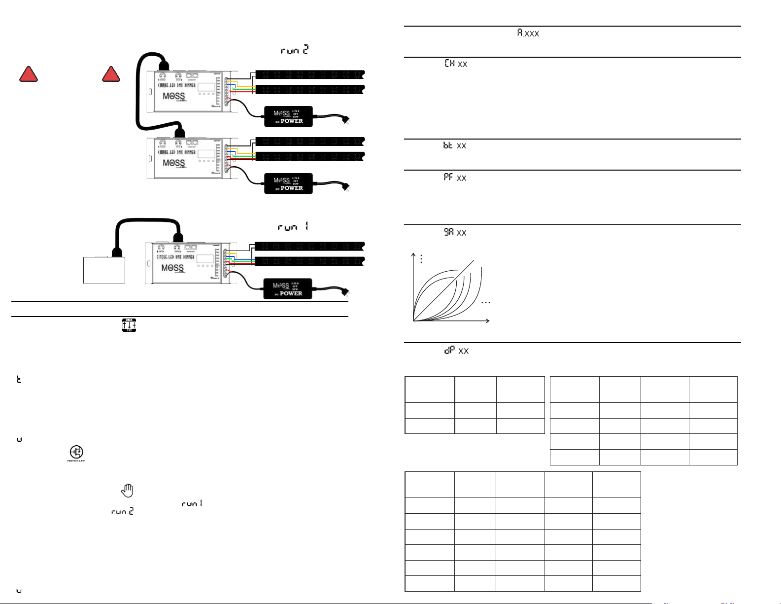
Switch between DMX Mode and Manual Mode
Program speed 1 to 16
Program brightness 1 to 8
Manual control over channels 1 to 5 from 00 to FL
5
Program 1 to 31. P01 channel 1 is on P02 channel 2 is on etc...
To enter Manual Mode use the “UP/DOWN” and set to “ ” press “ENTER”
then with the “UP” button set to “ ”. Press “BACK” to confirm. Power cycle the unit.
The following menu will apear.
Manual Mode (Master Mode)
When a short circuit occurs all the outputs will stop functioning and the LED display with flash.
Power cycle it (turn it off then on again) to restore normal operation.
Protect-A-FET
A.XXX
CH XX
B XX
PF XX
9A XX
DP XX
R N1
Decoding mode, default set to dP1.1
Switch between DMX Mode and Manual Mode
Dimming gamma curve value, default set to1.5
PWM frequency 500Hz to 35KHz, default set to 10KHz
Bit resolution 8bit/16bit, default set to 16bit
DMX channel quantity, default set to CH05
DMX address 1 to 507, default set to 001. The decimal after the “A” indicates reciving a DMX signal.
Using the “Up/DOWN” buttons you can cycle through the following menus.
DMX Mode (Decoder Mode)
OPERATION
+
R
G
B
W
+
_
DMX Console
DMX Decoder Mode
+
R
G
B
W
+
_
+
R
G
B
W
+
_
Master/Manual Mode
WIRING DIAGRAM
DO NOT WIRE WITH POWER APPLIED TO DEVICE
Only energize when all input and output
power wires have been securely
attached to terminal block. Connecting LEDs
while Cinque is energized can expose LEDs
to an overcurrent which will render them
permanently damaged.
CONSTANT CURRENT DEVICES ONLY
Constant voltage LEDs will not operate properly
and will likely be permanently damaged.
DO NOT USE IN WET LOCATIONS
Indoor use only.
Do not expose device to excessive moisture.
! !
WARNING


