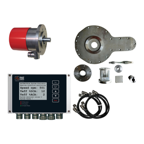
Motcom BeCOMS BCom User manual

BeCOMS®
BCom | Bearing Condition Monitoring
®
UserManual
Part No.: 1 900 00 00000
Release: 130301
(revision 190211)


motcom® BeCOMS® | BCom
User Manual
Release 130301 (revision 190211) Page iii
Declaration of Conformity
EMC-Directives: 2014/30/EU
Manufacturer motcom®GmbH
Kurt-Schumacher-Str. 28-30
D - 66130 Saarbrücken / Germany
Phone +49 681 8837904-0
Fax: +49 681 8837904-19
We declare on our own responsibility, that the products
Product description motcom®
Bearing Condition monitoring
Type designations BeCOMS®/ BCom
are in compliance with following norms:
EN 55011:2018-05/CISPR 11:2015 mod.+A1:2017
EN 55032/CISPR 22
EN 61000-4-2, EN 61000-4-3, EN 61000-4-4
EN 61000-4-5, EN 61000-4-6, EN 61000-4-8
66130 Saarbrücken, Germany, 2019, the 11th of February
Dipl.-Ing. Dieter Lott
Managing Director
We declare on our own responsibility, that the products
Bearing Condition monitoring
BeCOMS
®
/ BCom
®/ BCom
®
are in compliance with following norms:
EN 55011:2018-05/CISPR 11:2015 mod.+A1:2017
EN 55032/CISPR 22
EN 61000-4-2, EN 61000-4-3, EN 61000-4-4
EN 61000-4-5, EN 61000-4-6, EN 61000-4-8
66130 Saarbrücken, Germany, 2019, the 11th of February

motcom® BeCOMS® | BCom
User Manual
Release 130301 (revision 190211)
Page iv
Note: This User Manual is applicable for BeCOMS®and BCom.
To simplify this manual we oen named gures and pictures with BCom,
but always follow the instruction and information for BeCOMS too.
It is recommended to read this manual before commencing the repair, assembly
or commissioning of the Bearing Condition monitoring system!
Caution: The manufacturer’s warranty will become void if these instructions are
not followed!
i
!
!

motcom® BeCOMS® | BCom
User Manual
Release 130301 (revision 190211) Page v
Contents
1. System Description....................................................................... 1.1
2. Installation .................................................................................... 2.1
3. Commissioning............................................................................. 3.1
4. Performance / Maintenance Tests ................................................ 4.1
5. Troubleshooting............................................................................ 5.1
6. Repair........................................................................................... 6.1
7. Spare Parts................................................................................... 7.1
8. Attachments.................................................................................. 8.1

motcom® BeCOMS® | BCom
User Manual
Release 130301 (revision 190211)
Page vi

motcom® BeCOMS® | BCom
User Manual
Release 130301 (revision 190211) Page vii
Contents
1. System Description....................................................................... 1.1
1.1. Components.............................................................................................1.1
1.1.1. BCom- Principle ................................................................................1.1
1.1.2. BCom- System Overview..................................................................1.4
1.1.3. BCom- System Components ............................................................1.6
1.1.3.1. BCom Evaluator.........................................................................1.6
1.1.3.2. Connectors and pin-out of the BCom Evaluator ........................1.9
1.1.3.3. BCom Slip Ring Encoder (SRE) ..............................................1.10
1.1.3.4. Technical Data of BCom Slip Ring Encoder and Evaluator .....1.11
1.1.4. Editions of BCom System ...............................................................1.12
1.1.5. Versions of BCom System ..............................................................1.13
1.1.6. Intended Purpose of the Monitoring Software (opt.) .......................1.14
2. Installation .................................................................................... 2.1
2.1. General ....................................................................................................2.1
2.2. Installation Position ..................................................................................2.2
2.3. SRE Mechanical Adjustments ..................................................................2.3
2.4. Wiring Diagram ........................................................................................2.4
2.5. Software Installation (optional).................................................................2.5
2.6. PC Requirements (optional).....................................................................2.6
3. Commissioning............................................................................. 3.1
3.1. Pre-Commissioning Checks.....................................................................3.1
3.2. Syncronization of the BCom Sensor with the ring TDC
of the rst cylinder ....................................................................................3.2
3.3. Data Sampling..........................................................................................3.3
3.4. Alarm Setting and Triggering....................................................................3.4
3.4.1. Alarm Resetting.................................................................................3.6
3.5. Settings & Parameters / Using the Evaluator...........................................3.7
3.5.1. Basic Usage of the Evaluator............................................................3.7
3.6. Menu Structure.........................................................................................3.8
3.6.1. System measured values 1 (default screen).....................................3.8
3.6.2. System measured values 2...............................................................3.8
3.6.3. Graphic overview ..............................................................................3.9
3.6.4. SRE advanced infos .........................................................................3.9
3.6.5. Parameter setup .............................................................................3.10

motcom® BeCOMS® | BCom
User Manual
Release 130301 (revision 190211)
Page viii
3.7. BCom Logger measurement data storage and management (optional) 3.16
3.7.1. Compressing Data Files..................................................................3.17
3.7.2. Capturing the Graphic Screens.......................................................3.19
3.7.3. Archiving the Compressed Files .....................................................3.20
3.7.4. Manual Data Analysis for Compartment Localization .....................3.21
4. Performance / Maintenance Tests ................................................ 4.1
4.1. Function Test............................................................................................4.1
5. Troubleshooting............................................................................ 5.1
5.1. During Software Installation .....................................................................5.1
5.2. During Software Use ................................................................................5.2
5.3. Missing Control Signal .............................................................................5.3
5.4. Very low / strong signal on polar diagram ................................................5.4
5.5. Error code and Error description ..............................................................5.5
6. Repair........................................................................................... 6.1
7. Spare Parts................................................................................... 7.1
7.1. Main Spare Parts .....................................................................................7.1
7.2. Accessories ..............................................................................................7.2
8. Attachments.................................................................................. 8.1
8.1. Connection Assembly Instructions ...........................................................8.1
8.1.1. Preparing the Cable ..........................................................................8.1
8.1.2. Connecting the RS-485 converter.....................................................8.2
8.1.3. Assembling the plug..........................................................................8.3
8.1.4. Connection Cable - RS485 PCI Card to Evaluator ...........................8.4
8.2. Wiring Diagrams.......................................................................................8.6
8.3 Drawings ................................................................................................8.11

motcom® BeCOMS® | BCom
User Manual
Release 130301 (revision 190211) Page 1.1
1.1. Components
1. System Description
1.1.1. BCom - Principle
The BCom system can be used on engines and motors (turbines, pumps, etc.)
where the crankshaft is not electrically isolated from bearing shells. It utilises the
thermo-electrical (Seebeck) eect for monitoring the condition of the engine/motor,
bearings and slip surfaces, allowing to recognise failures at an early point, which
prevents large-scale part damages.
On diesel engines, the BCom system measures and evaluates thermal voltage
between the crankshaft and bearing shells, signalling changes that can be
interpreted as dangerous.
Dry friction
R
V
Fig. 1.1. Measurement principle in a diesel engine
This thermovoltage is very low (< 1 mV) during normal engine operation while the
lubrication oil acts as electrical isolation. If the oil lm between a rotating part and
its bearing becomes thinner and ruptures, which can be caused for example by
presence of metal particles in a bearing clearance, when the engine crankshaft
rubs against a bearing shell, the thermovoltage detected by SRE sensor rises.
Fig. 1.2. Redundant thermovoltage measurement

motcom® BeCOMS® | BCom
User Manual
Release 130301 (revision 190211)
Page 1.2
Fig. 1.3. Thermovoltage signal at the Data_Indicator
This information proved to be essential in early-stage diagnostic for engine parts, thus,
the BCom system is an important and eective tool in reducing engine maintenance
costs.
The thermovoltage and engine rotation speed are displayed at the control device,
Evaluator, and could be optionally displayed remotely on a PC. Both devices will
graphically indicate dangerous changes in measured values, so that the engine
personnel can immediately make decisions on further engine load and on repair
steps. The BCom system can also be connected to custom alarm or control devices
which can automatically stop the engine, preventing further engine damages. Thus,
the engine repair eorts and costs are minimised, while early detected problems can
be in most cases eliminated together with common maintenance works.
Thermovoltage peaks can be observed every time the engine starts, because the
oil lm is absent at this point and the crankshaft contacts the bearings. After a few
seconds the oil lm begins to build up and isolates crankshaft and bearing shells if
the engine is in a healthy condition.
The BCom system makes it possible to localise the beginning failure, because the
engine ring sequence is stored among other setting of BCom Evaluator. Parallel to
thermovoltage, BCom also monitors engine rotation speed and direction of rotation
with the help of an incremental encoder.
When a cylinder res, a higher thermo voltage signal is generated at spots aected
by dry friction due to high pressure. These voltage peaks superimposed with data
from the incremental encoder and with the ring sequence help to determine the
location where the oil lm ruptures.

motcom® BeCOMS® | BCom
User Manual
Release 130301 (revision 190211) Page 1.3
The thermovoltage value then sinks to a certain basic level that is specic to the
engine, and depends on its load and operating time. The BCom Evaluator monitors
all changes that occur during the engine operation and triggers an alarm should
these changes indicate danger.
Fig. 1.4. High thermovoltage signal at engine start-up
The eect of high voltage peaks also occurs when the engine is being shut down.
Some thermovoltage level can be measured even some time after engine stop,
until the temperatures at contact spots level out.

motcom® BeCOMS® | BCom
User Manual
Release 130301 (revision 190211)
Page 1.4
1.1.2. BCom System Overview
Fig. 1.5. System Overview
Local Alarm System
BeCOMS | BCom Evaluator
24V DC
SRE with mechanical Adapter Set
PC with Logger software / optional printer
• One Slip Ring Encoder (SRE) installed on the housing on a free end
of the crankshaft. The rotating shaft of the SRE is mechanically at-
tached to the free end of the crankshaft, usually with a vibration damper.
• One BCom Evaluator as the Local Control Panel where the measured
values are displayed and the signal evaluation is performed. These values
can also be displayed on a computer in the engine control room via RS485
communication cable with the help of BCom Data_Logger software which
provides online visualization and storage of the signals transmitted by the
Evaluator. Furthermore, stored measurement data can be viewed and analysed
by Data_Indicator software and motcom Analysis software.

motcom® BeCOMS® | BCom
User Manual
Release 130301 (revision 190211) Page 1.5
• One set of mechanical mounting/join adapters which includes shaft adapter
and cover, adapter housing with bearing, interface housing and cover.
• This manual; optionally, a backup CD with commissioning data.
• Optional PC with BCom Data_Logger software; a CD with Logger installation
and a soft copy of this manual.
i
BeCom Evaluator
optional PC with Logger software / printer
Mechanical adapter specific to the engine
cable set
SRE Slip Ring Encoder
BCom installation and commissioning are performed by motcom GmbH personnel
or by its authorized partners. Installation procedure includes training for technical
sta at the engine site.
Fig. 1.6. Scope of delivery for BCom Professional system
Fig. 1.7. Cut out model of a sample installation

motcom® BeCOMS® | BCom
User Manual
Release 130301 (revision 190211)
Page 1.6
The Evaluator consists of a metallic case, a liquid crystal display (LCD), three
LEDs (Shut-down, Pre-Alarm, System Ready), four control keys ( , ,
, , ) and one reset button .
The electronics and the display of the BCom Evaluator are installed in a closed,
shock-proofed, water, dust and EMC resistant aluminium case, protection class
IP 66.
The Evaluator is provided for mounting close to the engine or in the engine control
room. The Evaluator operates reliably at temperatures between 0°C to 70°C and at
relative humidity up to 80%.
The installation of the Evaluator is performed via 2 assembly rigs. If required, the
Evaluator can be mounted vibration-free. In each case you have to pay attention
that the connection cable is passed loose in a loop and without traction to the plug-
in connections.
The Evaluator is able to display the measurement values and BCom parameter
values on its LC-Display. It also provides some test procedures that can be
performed for BCom diagnostics.
Fig. 1.8. BCom Evaluator
1.1.3. BCom System Components
1.1.3.1 BCom Evaluator

motcom® BeCOMS® | BCom
User Manual
Release 130301 (revision 190211) Page 1.7
The control keys of the Evaluator are made as lm-press buttons. During operation,
please be careful and do not press them with spiky or sharp items, instruments like
knifes, screw-drivers or ball-pens. Just touch the buttons with a slight pressure by
a ngertip.
If needed, the keypad can be wiped with a mild cleaning agent. Please never use
a solvent!
After successful installation and testing by service technicians approved by motcom
GmbH, the settings of the Evaluator should not be changed. The Evaluator does
not require regular maintenance.
Note: Firmware updates for the Evaluator will be available and may be applied to
your system only by service technicians approved by motcom GmbH.
Firmware updates are free of charge. Please contact motcom GmbH or an
authorized representative for details and further information.
i
!

motcom® BeCOMS® | BCom
User Manual
Release 130301 (revision 190211)
Page 1.8
Fig. 1.9. Evaluator dimensions
For the exact dimensions, please see under 8.3 Drawings

motcom® BeCOMS® | BCom
User Manual
Release 130301 (revision 190211) Page 1.9
1.1.3.2. Connectors and pin-out of the BCom Evaluator
Connection at the Connectors of the Evaluator
123456
Pin Power
Supply Relays Serial Data
Link Reserved Reserved SRE
1+24V
(brown)
1st Alarm
Relay NO TxD / 232 SRE-1
20V
(black)
1st Alarm
Relay COM RxD / 232 SRE-2
31st Alarm
Relay NC CAN-H SRE-3
42nd Alarm
Relay NO CAN-L SRE-4
52nd Alarm
Relay COM RS485 + SRE-5
62nd Alarm
Relay NC RS485 - SRE-6
7Ready
Relay NO
RxD +
RS485 SRE-7
8Ready
Relay COM
RxD -
RS485 SRE-8
9Pre Alarm
Relay COM GND SRE-9
10 Pre Alarm
Relay NC GND SRE-10
11 Pre Alarm
Relay NO GND SRE-11
12 Pre Alarm
Relay NC GND SRE-12
Cable
Part.
No.
2xAWG 20
92000200000
12xAWG 20
92001200000
12xAWG 20
92001200000
12xAWG 20
92001200000
Con-
nector
Set
93000610000 93001220000 93001210000 93001220000
(for further information like wire colors, please refer to pages 8.6 - 8.10)
Table 1.1. Connections of Evaluator

motcom® BeCOMS® | BCom
User Manual
Release 130301 (revision 190211)
Page 1.10
i
1.1.3.3. Slip Ring Encoder (SRE)
The Connector-Set for the socket at the SRE: Art. No. 93001210000 has the wiring
assignment as listed on Table 1.1.on page 1.9 for the Connector-Set with the Art.
No. 93001220000
The Slip Ring Encoder is shaped as a cylinder. It is xed to a mounting board with
a ange and 4 cylinder-head screws. The SRE is identical for all engines. In each
individual case the mounting ange and the transmission shaft to the crankshaft of
the engine are adapted individually for each engine type. If necessary, SRE can be
dismounted for maintenance.
Info: The shaft and the mounting ange are determined, designed and manufactured
by motcom GmbH or by its authorized partners for each engine type. Only
in this case correct operation and trouble-free transmission of measurement
signals are guaranteed.
The Slip Ring Encoder contains a special slip ring with redundant carbon brushes
which receives the thermo-voltage signal from the crankshaft-engine system, and
an incremental encoder for measuring speed and rotating direction.
The SRE is designed to work in typical environment conditions of diesel engines.
Please also refer to the technical data on page 1.11.
Fig. 1.10. SRE

motcom® BeCOMS® | BCom
User Manual
Release 130301 (revision 190211) Page 1.11
1.1.3.4. Technical Data of BCom Slip Ring Encoder and Evaluator
Power Supply: 24V DC +30/-25%
Operating Current:
max. 1.5 A
Sensitivity: Adjustable in 5 steps
Relay-Outputs: Contact load for all relays:
max. 60V AC, 1A, 60VA / max. 60V DC, 1A, 60W
Alarm 1:
1 relay with 2 ground-free switch-over contacts, usually
congured as main alarm.
Wire break protection with 33 kOhm resistors (standard)
Alarm 2:
1 relay with 1 ground-free switch-over contact, usually
congured as pre alarm
Ready:
1 relay with 1 ground-free switch-over contact, energized
if system is fault-free
Interface: Serial Interface:
• RS485 for standardized industrial, bidirectional
communication
Communication Protocol:
• Modbus
• CAN Bus (optional)
User interface: LCD Display 240*128 dots
1 LED red “Shut-down”
1 LED red “Pre-Alarm”
1 LED green “System Ready”
Connection cable: for example:
• Scherer Kabel GmbH 12 AWG 20C UL
• Metrofunk 12 AWG 20C UL
• Huber + Suhner Radox MFHS-EMC
Environment
Conditions:
Ambient temperature in service:
0°C - 70°C for BCom Evaluator
0°C - 85°C for SRE
Ambient temperature in storage:
-25°C - 85°C
Protection:
IP65
(GL-environment category D, EMC 2)

motcom® BeCOMS® | BCom
User Manual
Release 130301 (revision 190211)
Page 1.12
* only Setup function for Evaluator, no transmission of measured values
Features Professional Advanced Basic
Hardware x = included o = optional - =
not included
Power Supply 24V DC +30/-25% x x x
Sensitivity adjustable in 5 Steps x x x
2 alarm relays, Function programmable x x x
1 ready relay x x x
RS485 Interface x x x *
LC-Display 240x128 dots x x x
System status LEDs
(System Ready, Prealarm, Shutdown) x x x
PC for data-logging which supports up to 6
systems x x -
Modbus Interface o o o
Software Capabilities of the Evaluator x = included o = optional - =
not included
Setup of BeCOMS / BCom system
via the user-interface of the Evaluator or
via RS485 (text based setup using a terminal
program)
x x x
Displays Thermosignal in % alarm level x x x
Displays Thermosignal AC eective in % alarm
level x x x
Displays Thermosignal DC eective in % alarm
level x x x
Displays Thermosignal in mV x x x
Triggers (Pre)Alarm using AC and DC thermo
signal x x x
Auto-check of SRE sensor by Evaluator x x x
Error Monitoring on Display x x x
AC and DC alarmlevels separately adjustable x x x
Displays engine speed in RPM x x x
Triggers overspeed alarm x x x
Dierent AC alarmlevels for 2 adjustable RPM
levels x x x
Shows measured values in a graphic overview
display x x x
Recording of data for Damage Localization x - -
Recording data of combustion cycle performance x - -
Data-output via RS485 x x x
Data-output via RS485 for combustion cycle x - -
Data-output via RS485 for Damage Localization x - -
Table 1.2. Features
1.1.4. Editions of BCom System
Table of contents
Other Motcom Measuring Instrument manuals
Popular Measuring Instrument manuals by other brands

Agilent Technologies
Agilent Technologies Flow Tracker Series Reference manual

Tektronix
Tektronix 7D01 introduction

Oxford Optronix
Oxford Optronix OxyLite user manual

Cell Dynamics
Cell Dynamics W8 First installation manual

Blue-White industries
Blue-White industries F-1000 instruction manual

OPHIR
OPHIR ORION user manual

Hornbach
Hornbach 10390468 Original instructions

S+S Regeltechnik
S+S Regeltechnik AERASGARD RLQ-W Operating Instructions, Mounting & Installation

YOKOGAWA
YOKOGAWA 2016 user manual

MULTISPAN
MULTISPAN MFM13 quick start guide

DAKOTA ULTRASONICS
DAKOTA ULTRASONICS DFX-7 Operation manual

Hanna Instruments
Hanna Instruments HI708 instruction manual