Kane 9206 Quintox User manual

1
KANE9206
Quintox Flue Gas Analyser
Stock No: 19332-5 November 2014
© Kane International Ltd

2
CONTENTS
Page No:
SAFETY WARNING 7
KANE9206 OVERVIEW 7
STANDARD FEATURES 7
HANDSET 7
MAIN ANALYSER UNIT 8
OPTIONS 9
ELECTROCHEMICAL SENSORS 9
OTHER OPTIONS 9
PROBE OPTIONS 9
SPARE PARTS LIST 9
KANE9206 WITH KANE LIVE PC SOFTWARE 10
ANALYSER LAYOUT AND FEATURES 11
HANDSET FEATURES 11
ANALYSER LAYOUT 12
ANALYSER LAYOUT WITH KMDM110/230 SAMPLE
CONDITIONING UNIT FITTED 13
TYPICAL PROBE CONFIGURATION (KMCP6) 14
ANALYSER CONNECTIONS 15
GETTING STARTED 16
BEFORE TAKING READINGS 16
MENU: ALL THE OPTIONS 17
STATUS: ESTABLISHING THE ANALYSER’S
SET-UP 18

3
SETUP: CONFIGURING THE ANALYSER’S
SET-UP 20
LANGUAGE 20
MAIN PURGE 21
PRINTER 21
AUTO SET TIME 22
SET TIME 22
SET DATE 23
HEATER STATUS 23
SELECT ANALYSER UNIT SERIAL NUMBER 23
WIRELESS SET UP 24
WIRELESS PASSKEY 24
ANALYSER UNITS: CONFIGURES ALL THE
DATA SOURCES AND SETTINGS 25
FUEL ORIGIN 25
FUEL TYPE 25
EFFICIENCY 25
GAS UNITS 26
TEMPERATURE 26
PRESSURE 26
SET PERCENTAGE REFERENCE 02 26
SET NOx CALCULATION 26
SET COMPENSATION 26
CONVERSION FACTORS 26
CO ALARM 27
CO ALARM SET 27
CO ALARM LEVEL 27
SCREEN 28
CONTRAST 28
B’LIGHT 28
MODE 28
LINES 29

4
REPORTS: CONFIGURES REPORTS 30
VIEW REPORTS 30
DELETE ALL REPORTS 31
AUTO LOG TIME 31
START AUTO LOG 31
START AUTO PRINTING 31
HEADER 1 31
HEADER 2 31
FORM FEED 31
SERVICE 32
MANUAL AIR ZERO 32
MANUAL PRESSURE ZERO 32
BEFORE USING THE ANALYSER FOR THE
FIRST TIME 33
SAFETY WARNING 33
FIRST TIME USE 33
NORMAL START UP SEQUENCE 33
EVERY TIME YOU USE THE ANALYSER 33
AUTOMATIC CALIBRATION 34
MAIN MEASUREMENT SCREEN 36
IN SMALL FONT MODE 36
IN LARGE FONT MODE 37
SAMPLING THE FLUE GAS 39
LONG TERM MONITORING 39
KMDM110/230 SAMPLE CONDITIONING UNIT 40
SETTING UP 40

5
MAINTENANCE 42
EMPTYING AND CLEANING THE IN-LINE
WATER TRAP 42
CHANGING THE PARTICLE FILTER 42
CHARGING THE BATTERY 43
CHANGING THE PAPER ROLL 43
TO START PAPER FEED 43
CHANGING THE PRINTER RIBBON 43
PROBLEM SOLVING 45
HOW TO GET EXPERT HELP 45
ANALYSER ANNUAL RECALIBRATION AND
SERVICE 46
RETURNING YOUR ANALYSER TO KANE 47
PACKING YOUR ANALYSER 47
SENDING YOUR ANALYSER 47
WHEN WE RECEIVE YOUR ANALYSER 47
SERVICE RETURNS 48
PRODUCT SPECIFICATION 50
UNIT 50
OPTIONAL IR MODULE 51
HANDSET 51
EXTENSION CABLE 52
MAIN BATTERY AND OPTIONAL HEATER BATTERY 52
BATTERY CHARGER 52
PUMP 52
INTEGRAL PRINTER 52
AMBIENT OPERATING RANGE 52
KMHL3000: HEATED SAMPLE LINE 53
KMHP1200: HEATED PROBE 53
KMDM110/230: SAMPLE CONDITIONING UNIT 53
PROBE 53
OPTIONAL PORTABLE PRINTERS 53

6
ELECTROMAGNETIC COMPATIBILITY (CE)
STATEMENT 54
END OF LIFE DISPOSAL 54
BATTERY DISPOSAL 54
EN50379 REGULATED INSTRUCTIONS 55
APPENDICES 60
A. PARAMETER MEANINGS 60
B. NOx CALCULATIONS 63
ONLY AN NO SENSOR FITTED 63
WORKING IN PPM: NOX REFERENCED TO NO 63
WORKING IN MG/M3: NOX REFERENCED TO NO OR NO2 63
WORKING IN MG/M3: REFERENCED TO NO 63
WORKING IN MG/M3: NOX REFERENCED TO NO2 64
NORMALISING READINGS 64
BOTH NO AND NO2 SENSORS FITTED 64
WORKING IN PPM: NOX = NO + NO2 64
WORKING IN MG/M3 64
NOX = SUM 64
NOX = NO 64
NOX = NO2 64
NORMALISING READINGS 65
ONLY AN NO2 SENSOR FITTED 65
NORMALISING READINGS 65
HIGH CO PURGE OPERATION 65
C. COMBUSTION EFFICIENCY CALCULATION 66
D. CALCULATION OF FUEL DATA 68
PRODUCT REGISTRATION 69

7
SAFETY WARNING
This analyser must only be used in well-ventilated locations by trained and competent
persons after due consideration of all the potential hazards and with regard to local and
National regulations and guidelines.
The analyser extracts combustion gases that may be toxic in relatively low concentrations.
These gases are exhausted from the bottom of the instrument.
Users or portable gas detectors are recommended to conduct a “bump” check before
relying on the unit to verify an atmosphere is free from hazard.
A “bump” test is a means of verifying that an instrument is working within acceptable limits
by briefly exposing to a known gas mixture formulated to change the output of all the
sensors present. (This is different from a calibration where the instrument is also exposed
to a known gas mixture but is allowed to settle to a steady figure and the reading adjusted
to the stated gas concentration of the test gas).
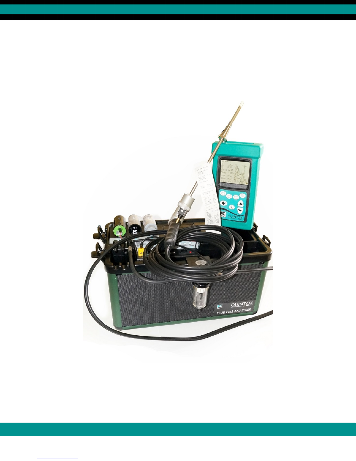
KANE9206 OVERVIEW
The KANE9206 is broadly based on the KM9106 and whilst retaining many of its core
features has been significantly enhanced. The most visible difference is the large
graphical display on the handset. Up to 15 lines of text/data can be displayed. The
handset links to the main analyser unit using wireless communications or the normal
cable. It also has a USB connector to link to a PC via a cable and has an infra-red output
to link to the portable Kane KMIRP-2 printer.
The main analyser unit also contains significant enhancements over the KM9106.
STANDARD FEATURES:
19301 Battery charger
18277 UK mains lead
18276 EU mains lead
18275 US mains lead
19332 Instruction manual
Kane 'LIVE' software download from Kane website
HANDSET: KBHS
Wireless and cable connectivity to analyser unit.
Wireless and USB connectivity to PC
GPS location
IR connectivity to Kane IRP portable printers
Monster data storage memory (64k records)
Graphical display with choice of large or small fonts.
Battery rechargeable via main unit or mains charger

8
MAIN ANALYSER UNIT: AS STANDARD KANE9206
Measures:
Oxygen
Carbon monoxide
Ambient temperature
Atmospheric pressure
Inlet temperature
Flue temperature
Differential pressure
Features:
Main purge
Flow control*
NiMh battery packs
Plain paper printer
*Flow control
To compensate for different suction levels in flues, hose lengths and filter contamination
levels, all of which can affect the flow of sample gases, there is an active flow control
system fitted to the KANE9206.
It operates as follows:
Every time the instrument is turned on and finishes its first fresh air purge cycle from inside
the analyser, it measures and records the pump pressure just prior to the sensor manifold
whilst the pump is at 100% flow rate. During service calibration & normal use, the pump
speed is automatically adjusted to 70% of the purge flow rate to maintain consistent flow.
The flow control can cope with typically 100 mbar suction in a flue and still maintain the
same nominal flow as that present under ambient conditions.

9
OPTIONS:
ELECTROCHEMICAL SENSORS : (UP TO 5 SENSORS)
CHOOSE FROM:
KNO1L/Q Nitric oxide (low range)
KNO1H/Q Nitric oxide (high Range)
KNO2/Q Nitrogen dioxide
KSO2L/Q Sulphur dioxide (low range)
KSO2H/Q Sulphur dioxide (high range)
KH2S/Q Hydrogen sulphide
OTHER OPTIONS:
KHSA Heater for toxic sensors
KHC/Q IR triple bench (CO, HC, CO2)
KHPUR/Q High/low CO protection (solenoid and pump)
WTS9206P Pumped water trap
KMHL3000 Heated line
KMHP1200 Heated probe
KMDM220 Gas Conditioning Module
PROBE OPTIONS:
KMCHLP6 High temperature 1 metre removable shaft
KMCHP6 High temperature 285mm removable shaft
KMCHSLP6 Smoke probe with high temperature 1 metre removable shaft
KMCHSP6 Smoke probe high temperature 285mm removable shaft
KMCSP6 Smoke probe with 285mm removable shaft
KMCLP6 1 metre removable shaft
KMCP6 285mm removable shaft
SPARE PARTS LIST:
OS11 Oxygen Sensor
KCO1/Q Carbon monoxide (H2 compensated)
IMP3R Printer ribbon
IMP10P Printer paper
SF1/5 Chemical filter
AF2 Particle filter assembly
PF2/10 Particle filter filter pack
WN8 Water trap filter pack
BP9206 Battery pack
WTS9106 Water trap assembly
19403 Peri pump tubing

10
KANE9206 WITH KANELIVE PC SOFTWARE
KANELIVE is a free download that runs on Windows based PCs and allows live display
and graphing of data. It can be downloaded from the Kane website (www.kane.co.uk)
once an analyser has been registered in the MY KANE section of the website.
In the current configuration, the handset needs to be connected to the main unit by a cable
and the wireless setting for the handset needs to be changed to TO PC using MENU,
SETUP, WIRELESS SETUP.
Once this has been selected, go to the PC and select DEVICES & PRINTERS.
Click ADD A DEVICE.
All devices within range will be displayed in icon form. The KANE9206 handset will be
displayed as:
KANE9206HS
999999107
where the 9 digit number is the serial number of the handset.
Double click on this. Now follow the instructions.
Then enter the passkey: 1111
Click on the TICK BOX and then AT SERIAL CONFIGURE and then FINISH.
Now click on KANELIVE to initiate the programme.
Select your analyser type by clicking on the analyser name displayed on the middle of the
bottom line of the screen. If more than one analyser has been enabled a drop down will
appear. Click on the analyser of your choice.
Then click CONNECT and wait for its colour to change to green.
Then click START which will change to green.
After a few seconds live data will be displayed.

11
ANALYSER LAYOUT AND FEATURES
HANDSET FEATURES
INFRA RED LED
REMOTE LEAD SOCKET
(8 PIN DIN)
PUMP ON/OFF KEY
PRINT KEY
ENTER KEY
ON/OFF KEY
MENU KEY
STORE KEY
SCROLL UP KEY
SCROLL DOWN KEY
GRAPHICAL DISPLY
PROTECTIVE COVER
BATTERY
COMPARTMENT
(BACK)
SERIAL USB CONNECTION

12
ANALYSER LAYOUT
OXYGEN SENSOR
FILTER BRIDGE OR
SULPHUR FILTER
PARTICLE FILTER
BATTERY ENCLOSURE
PRINTER UNIT
HANDSET
(STORED IN
POCKET)
CONNECTION LEAD
FOR OXYGEN SENSOR
DUAL PRESSURE
PORTS
WATERTRAP
CONNECTION
WATERTRAP
LOCATED ON SIDE
OF INSTRUMENT
ACCESSORY STORAGE SPACE
(LEADS, WATERTRAP ETC)
INSTRUMENT CASE

13
ANALYSER LAYOUT WITH KMDM110/230GAS CONDITIONING
MODULE FITTED
OXYGEN SENSOR
PARTICLE FILTER PRINTER UNIT HEATED LINE
CONNECTION
GAS DRYER
ASSEMBLY
INSTRUMENT CASE
WATERTRAP CONNECTION
DUAL PRESSURE PORTS
OXYGEN SENSOR
CONNECTOR
FLUE SOCKET INLET SOCKET
AUX CONNECTOR
(25 PIN 'D')
ANALYSER 'ON' SWITCH
REMOTE HANDSET
CONNECTION
(8 PIN DIN)
RED POWER LED
CHARGER INPUT SOCKET
REMOTE HANDSET CONNECTION
(8 PIN DIN)

14
TYPICAL PROBE CONFIGURATION (KMCP6)
THERMOCOUPLE CONNECTION (FLUE)
INLET SOCKET FOR
OPTIONAL AIR
TEMPERATURE PROBE
PROBE GAS CONNECTION
TO WATERTRAP
WATERTRAP LOCATED
ON SPIGOT IN CASE
DEPTH STOP CONE
SAMPLING PROBE

15
ANALYSER CONNECTIONS
CHARGER INPUT SOCKET
DUAL PRESSURE
PORTS
(8 PIN DIN)
OXYGEN SENSOR
CONNECTOR
FLUE SOCKET
INLET SOCKET
AUX CONNECTOR(25 PIN 'D') ANALYSER 'ON' SWITCH
REMOTE HANDSET CONNECTION
(8 PIN DIN)
RED POWER LED

16
GETTING STARTED
Check that you have all the items you have ordered.
Before attempting to use the analyser to take readings it is recommended that the
batteries are fully charged.
When the charger is connected to the analyser and powered up the red LED by the
charger socket will flash until the batteries are fully charged. Once the batteries are fully
charged the LED will no longer be illuminated.
To charge the handset; connect the handset to the main analyser unit using its cable.
Whilst switched off, but charging, the display will show the Kane logo and a battery
charging icon in the bottom right hand corner of the handset screen. Note: the handset
battery is charged via the external battery charger and not from the analyser’s internal
battery. Once the handset battery is fully charged the icon will disappear from the screen.
The handset can also be charged directly using the mains charger as used for the
analyser.
BEFORE TAKING READINGS
You need to establish the current set up of the analyser and then make the changes that
you need to suit exactly what you want to do.
So press the MENU key and then select STATUS as described below.

17
MENU: ALL THE OPTIONS
Press the MENU key.
----------------------------------MENU---------------------------------
> STATUS
SETUP
ANALYSER UNITS
CO ALARM
SCREEN
REPORTS
SERVICE
MANUAL AIR ZERO
MANUAL PRESSURE ZERO
11:33:56 23/03/13 S04
The > symbol acts as the cursor. It can be moved up or down by pressing the UP or
DOWN keys.
Having made a selection press the ENTER key.
The bottom line of this screen lists:
the time
the date
the number of satellites being received
the wireless connection status
the estimated charge in the handset battery

18
STATUS: ESTABLISHING THE ANALYSER'S SET-UP
Press MENU and then select STATUS by pressing ENTER.
----------------------------------MENU---------------------------------
HANDSET SW19170 V1.01
SERIAL NO. 999999107
ANALYSER SW19171 V1.01
SERIAL NO, 999999207
MAIN BATTERY 98%
HEATER BATTERY 100%
CAL DATE = 331
11:33:56 23/03/13 S04
This screen lists :
the software version in the handset
the handset serial number
the analyser unit software version number
the analyser unit serial number
the estimated charge in the main battery
the estimated charge in the heater battery (if fitted)
the number of days before annual re-calibration is due

19
Press DOWN to move to the next screen.
----------------------------------MENU---------------------------------
REFERENCE O2 = 3.0%
NOx CALCULATION = SUM
REFERENCE NOx = 5%
EFFICIENCY = NET
FUEL = NATURAL GAS
FUEL SOURCE = UK
CO ALARM SET = NO
CO ALARM LEVEL = 400ppm
11:33:56 23/03/13 S04
Press DOWN to move to the next screen.
----------------------------------MENU---------------------------------
AUTO PURGE = YES
AUTO ZERO = NO
AUTO PUMP FLOW = NO
MAIN PURGE DURATION TIME = 2 mins
MAIN PURGE INTERVAL TIME = 30 mins
LOG 0006
AUTO LOG/PRINT TIME = 30 mins
START AUTO LOG = NO
START AUTO PRINTING = NO
11:33:56 23/03/13 S04
Press DOWN to move back to the first screen.
Press PRINT to print this status on the analyser’s printer.
Press MENU to EXIT.

20
SETUP: CONFIGURING THE ANALYSER’S SETUP
----------------------------------MENU---------------------------------
> LANGUAGE
MAIN PURGE
PRINTER
AUTO SET TIME
SET TIME
SET DATE
HEATER STATUS
SELECT ANALYSER BOX SERIAL No.
WIRELESS SETUP
WIRELESS PASS KEY
BACK
11:33:56 23/03/13 S04
LANGUAGE:
Align cursor using UP or DOWN keys, then press ENTER.
Use UP or DOWN keys to scroll through the selection.
Press ENTER to select.
Table of contents
Other Kane Measuring Instrument manuals