Motic MLC-150C User manual

ENS LYON
tlotîc
Cold Light Power Supply
MLC-1 50C
Instruction Manual
WWW.MOTIC.COM
MOTIC INCORPORATION LTD.
C€ @ ,t- Listed Product E2so223
f;!;.lffiiir1l9.1:

We are constantly endeavoring to improve our instruments and to adapt them to the
requirements of modem research techniques and testing methods. This involves modification
to the mechanical structure and optical design of our instruments.
Therefore, all descriptions and illustrations in this instruction manual, including all
specifications are subject to change without notice.
To ensure proper use, please read this manual carefully before using the MLC-150 cold light
source.

To meet the demands of both international and domestic markets, Motic has developed the new
MLC- l50C cold light source. Besides a switching power supply that ensures a regulated voltage
for the lifetime of the halogen bulb, many other safety precautions have been taken to provide a
safe and reliable cold light source. In addition, an infrared filter and filter assembly have been
incorporated to minimize halogen light heat output in order to achieve cold light illumination and
meet the objectives of many kinds of color temperature light rays.
The MLC-150C can be applied extensively in various fields that require bright light illumination
including' microscopy, medicine, education, and many other areas of scientific research. With a
sturdy construction, practical and aesthetic design, minimal working noise and user friendly
controls' it is a welcome addition to any laboratory. A large selection of additional fiber liehts are
also available to choose from.

Contents
1. Specifïcations
2. Fiber optic lights
3. Usage
4. Installing the filter
5. Changing the bulb
6. Color temperature display
7. Maintenance and Care
8. Accessories
4
5
7
l0
11
L2
13
I4

1. Specifications
1. Input rating
2. Output rating
3. lnternal i lluminator
4. Illuminarion outpur
5. Color temperature output
6. Environment
T.Breaking capacity
S.Intemal fuse
9. Average problem-free usage
10. Total area
11. Weight
AC115V/AC230V +15% 50/60H2 2OOW
DC3V-DC2|Y + t0% (halogen lamp working voltage)
7A (MAX)
2Mf50W EKE Halogen lamp; Working life 200H
> 120000LX
A. With no filter: 2500K-3200K
B. With filter: 5000K (Max)
A. Active temperature : 0C^45C
B. Storage temperature: -10"C^60C
C. Active and storage humidity:
At 31 degrees, corresponding humidity at80Vo,
At 40 degrees, decrease conesponding humidity to 5OVo.
D. Elevation: 2000m max
E. Installation Category: II
F. Pollution rating:2
G. Active environment quality: conductive dust and corrosive
gas free.
H. Indoor use only
1750VAC / 5MA/one minure without breaking
T5AL250V low breaking capacity glass tube fuse (with delay)
MTBF>lOOOOH
220 (w) X 193 (L) X 112 (H) mm
3Ks

2. Fiber optic lights
Note: Customizations can be made for user-specific requirements.
Serial No. Length lYpe Diameter Output plug Microscope
sP990072 1.5M Flexible ù7 Straight
K-model
stereomicroscope,
verlical
illuminator
sP9900734 2M Flexible ô5 Straight Industrial
microscopes
sP9900738 2M Flexible ôs Elbowed Industrial
microscopes
sP990074 1M Flexible ô5 Inner diameter
61MM Ring lamp
Stereomicroscopes
K and
SMZ168 models
sP990075 0.5M Hard-tube
(single) ô8 Straight
Gemological
microscopes
GM168 and
GM143 models
sP990076 0.5M Hard-tube
(twin) ô s.6 Straight K-model
stereomicroscope
Table 1

Flexible fiber optic light -
sP990072
Industrial microscope fiber optic light -
sP990078
Hard-tube single fiber optic lighr -
sP990075
Industrial microscope fiber optic light -
sP99007A
Ring light -
sP990074
'/
g
'. t-
t;,
Hard-tube twin fiber onric liphr -
sP990076

3. Usage
1. Confirrn your local power supply rating and then at the back of the unit adjust the voltage
conversion switch accordingly (115V or 230V).
1. Controller cable input
2. Light control mode switch
3. Voltage conversion switch
4. AC input
Diagram 1
2. Users are able to choose the tight intensity control method as required. Shorl-range control
method: Switch the 'Light control mode switch'to 'LOCAL' (see diagram 1). Place the unit
on your desk and use the light intensity adjustment knob on the front panel of the unit to
adjust the light intensity. Remote control method: Switch the 'Light control mode switch' to
'REMOTE' (see diagram 1). Place the unit anywhere within 1.5 meters (as the cable allows)
of your person, plug the remote control cable into the main unit using the DB9 plug and begin
to adjust light intensity using the remote control.
1. AC power switch
2.Light intensity adjustment dial
3. Lamp housing screws

i:||ee
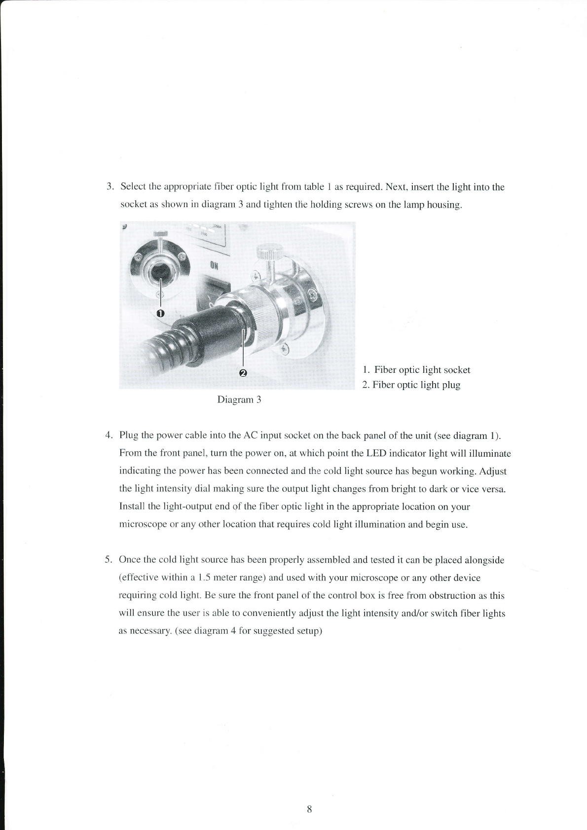
3. Select the appropriate fiber optic light from table 1 as required. Next, insert the light into the
socket as shown in diagram 3 and tighten the holding screws on the lamp housing.
',t* '* | -:
x{
1. Fiber optic light socket
2. Fiber optic light plug
Diagram 3
Plug the power cable into the AC input socket on the back panel of the unit (see diagram 1).
From the front panel, turn the power on, at which point the LED indicator light will illuminate
indicating the power has been connected and the cold light source has begun working. Adjust
the light intensity dial making sure the outpllt light changes from bright to dark or vice versa.
Install the light-output end of the fiber optic light in the appropriate location on your
microscope or any other location that requires cold light illumination and begin use.
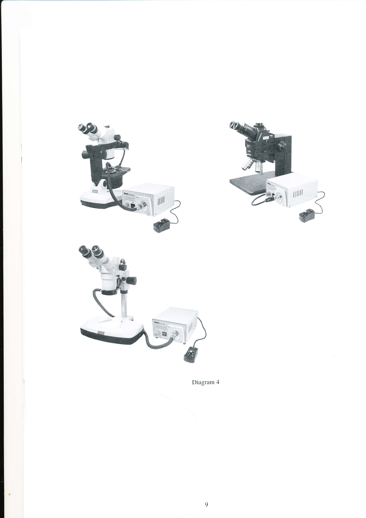
Once the cold light source has been properly assembled and tested it can be placed alongside
(effective within a 1.5 meter range) and used with your microscope or any other device
requiring cold light. Be sure the front panel of the control box is free from obstruction as this
will ensure the user is able to conveniently adjust the light intensity and/or switch fiber lights
as necessary. (see diagram 4 for suggested setup)
ôx
4.
5.

%:
Diagram 4

4,, Installing the :filter
Users may install filters as required. To install a filter: Loosen the holding screws on the lamp
housing and remove the lamp housing from the main unit. Find the filter installation location (at
the front of the housing, against the fiber optic light socket) and insert the filter (making sure it is
facing the right direction) as shown in diagram 5 below. Generally, a glass filter unit has been
installed at the point of manufacture. If it is required that the glass filter slice be changed, please
note that it must be installed facing the proper direction. The side of the glass with the coated film
must be installed facing the incoming light ray or the glass slice will become damaged.
1. Filter installation location
2. Filter unit
3. Filter plating
Diagram 5
10

5. Ghanging the Bulb
If the bulb is used passed its specified lifetime, it may lead to damage and should thus be changed.
To change the bulb: pull out the power cable plug, make sure the lamp housing has cooled
sufficiently, loosen the lamp housing screws and remove the lamp housing from the unit. Next,
push down the steel wire holding the bulb in place, and gently remove the bulb. Replace with a
bulb of the same specifications (21Vl150W), insert the lamp housing back into the main unit and
tighten the holding screws (see diagrams 6 and 7 below).
,rr@
r. ta
:'" pÇ
,rrt | *
"" lol
,:: i:t
l'i
II
Diagram 6
Diagram 7
il

6, Golor temperatu:re display
An LED indicator is employed to display the current light output color temperature value. When
the light intensity dial is adjusted, the output light intensity and color temperature value will
change in accordance. The value displayed on the LED indicator (the light moves from left to right
with intensity) represents the current light output color temperature value when no filter has been
installed. If a standard filter has already been installed, a value of 500 must be added to the value
displayed on the LED. For example, if the LED is displaying its maximum value of 3200K, add
500 to this value to calculate the real color temperature (3700K). If a different color filter is being
used, the color temperature displayed by a color temperature measurement instrument should be
taken as standard.
Diagram 8
TZ

-') -
7. Maintenance and Care
Use the instrument in an area with good air circulation. Do not place large devices or devices
that emit large amounts of heat near the instrument. When the instrument is in use, make sure
the air intakes at the base and sides and the fan at the back of the unit are kept free from
obstructions as this will ensure proper heat dispersal. As well, do not cover the outer surface of
the instrument with paper, cloth or any other object that will affect heat dispersal.
If the instrument has been used for a period time and suddenly does not illuminate, it is
possible the bulb has reached the end of its life. A new bulb of the same specifications should
be installed. When in use, the instrument should not be frequently turned on and off as this will
shorten the life of the bulb and damage the electronics.
When installing and using the internally housed halogen bulb and filter, protect from oil stains
by avoiding contact with bare hands. If contaminated, use absorbent cotton dipped slightly in
an ethyl-alcohol mixture to wipe clean.
4. Do not position the equipment so that it is difficult to unplug the power supply cord from the
unit.
1.
The instrument should be kept clean and free of dust, moisture and oil to ensure the machine's
proper electrical insulation. When cleaning the outer surface of the instrument, do not use
water or any corrosive cleaning agents. Use a clean piece of silk cloth dipped slightly in
benzene to wipe clean. If the instrument is not to be used for an extended period of time, place
it back into its box and store in a low humidity environment.
When using the fiber optic light, do bend at a right-angle or even slightly less than a
right-angle as this will cause the optic fiber to break. The light's input/output plugs and the
flexible tube's joints are especially susceptible to breakage.
Before using this instrument, ensure the local power supply voltage rating is the same as at
least one of the voltage conversion switch settings on the back panel of the unit. As well, be
sure not to randomly switch the voltage setting at any time as this may damage the instrument.
Users should respect local safety protocol and must bear full responsibility for the safe
operation of this instrument. Should the instrument become damaged, do not attempt to
disassemble and/or repair. Contact the distributor's service department or send the instrument
directly to the manufacturer for repairs.
6.
8.
t3

8. Accessories
AC input power cable (Equip in accordance with local power ratings)
Hand remote (with 2 meter extension cord))
Optical fiber light cable (Select specifications according to user needs)
Filter unit (Color temDerature 5000K)
l4

tloJic C€@ NO.: SPO10132B
Motic Incorporation Ltd. (Hong Kong)
Rm 2907-8, Windsor House, 311 Gloucester Road, Causeway Bay, Hong Kong Tel: 852-2837 0888
Motic Instruments Inc. (Canada)
180-4320 Viking Way Richrnond, B.C. V6V 2L4 Canada
For inquiries in UK (UK)
Saracens House, 25 St. Margarets Green, Ipswich, IP4 2BN, Suffolk, UK TeI: 44-14132 81909
Motic Deutschland GmbH (Germany)
Gewerbepark Spilbug, Spilburgstrasse 1 D-35578 Wetzlar Germany Tel: 49-6,141-210 010
Tcl:1-817-917 4717 Fax: 1-604-303 9043
Fax: 852-2882 2792
Fax: 44-(0)-14732 1 1508
Fax: 49-6441-210 0122
Motic Spain, S.L. (Spain)
Poligon Industrial Les Corts, Cami del Mig, I 1 2 08349 Cabrera de Mar, Barcelona Spain Tel 34-93-7 56 6286 F ax: 34-93-7 56 6287
Website : http ://www.motic.com
E-mail : [email protected]
Motic China Group., Ltd. (China)
Motic Building, Torch Hi-Tech Industrial, Development Zone, Xiamen PR.C. Tel: 86-0592-562 7866 Fax: 86-0592-562 7855
O2000-2004 Motic China Group Co., Ltd. All rights reserved. Motic is a registered trademark and service mark of Motic China Group
Co., Ltd. Microsoft Windows logo açe registered trademarks of Microsoft Corporation. All other tradgmarks are the property of their
respectrve owners.
Design Change: The manufacturer reserves the right to make changes in instrument design in accordance with scientific and mechanical
progress, withôut notice and without obligation.
Table of contents
Popular Power Supply manuals by other brands

Elenco Electronics
Elenco Electronics XR-38 operating instructions

Sanela
Sanela SLZ 06 Mounting instructions

Pulsar
Pulsar PS-602425 instruction manual

Elettrotest
Elettrotest CPS/T Series user manual

MIRKA
MIRKA MIN6522511 operating instructions

INIM Electronics
INIM Electronics IPS24060G Installation and Maintenance