Motomaster ELIMINATOR 011-2047-2 User manual

INSTRUCTION
MANUAL
400 W POWER INVERTER
PURE SINE WAVE
GF
2.1A
SAVE THESE INSTRUCTIONS!
This manual contains important safety and operating instructions.
Read all instructions and follow them with use of this product.
Questions? Call Customer Service Hotline: 1-877-466-8191
model no. 011-2047-2

TABLE OF CONTENTS
1model no. 011-2047-2 | contact us : 1-877-466-8191 2
INTRODUCTION
INTRODUCTION
Read and understand this manual before installing and operating this inverter. Keep this
manual for future use.
It delivers a true AC sine wave identical to that of commercial power. Use this inverter to
power AC appliances in your vehicle. Pure Sine Wave AC means that your sensitive
electronics, such as audio/video systems, computers, and communications equipment will
operate properly. Furthermore, appliances with motors operate cooler, quieter, and more
efciently when they are powered by pure sine wave AC.
The inverter is powered from 12 volt DC and it will continuously deliver 400 watts AC power
at 115 volts, 60 Hz. Superior surge capability of 800 watts allows the inverter to start most
difcult motorized appliances. Advanced microprocessor-controlled circuits run cooler and
are more reliable than competing units. The Pure Sine 400 W operates at high efciency (up
to 90%), that results in long run time and extended battery life compared to other inverters
with this level of power output. A 2.1 A USB power port provides a convenient way to power
USB devices, including tablets, e-readers, smart phones, and other mobile electronics.
This inverter bonds neutral to ground, just like utility power. The enclosure vents have been
minimized to reduce the risk of pest intrusion in arid tropical climates.
This inverter has added safety features including cETLus certication (UL458, CSA 22.2),
conformal coating to protect circuits from dust and moisture, ground fault protection, and
DC terminal protection.
INTRODUCTION
SPECIFICATIONS
WARNING
KEY PARTS DIAGRAM
OPERATION
TROUBLESHOOTING
WARRANTY
2
3
4
5
8
11
12

SPECIFICATIONS
3model no. 011-2047-2 | contact us : 1-877-466-8191 4
WARNING
SPECIFICATION WARNING
Output waveform
Input
Output
True Rated Power™
Peak power
Maximum efciency
Frequency
Total harmonic distortion (THD)
No load current draw
Battery low alarm
Battery low shutdown
Over voltage shutdown
Cooling system
AC output sockets
USB power port
Power output control
Dimensions
Net weight (approximate)
Battery Clamps with ring connectors
Pure sine wave
12 V DC
115 V AC
400 W (24-hour continuous)
800 watts
88%
60 Hz
≤ 3%
< 0.6 A
10.5 V - 11.0 V DC
10.0 V - 11.0 V DC
15 V - 16.3 V DC
Thermo fan
2 North American standard
5 V, 2.1 A
AC On/Off Switch
9 5/16 x 4 11/16 x 2 13/16" (23.6 x 12 x 7.1 cm)
2 lb 10 oz (1.2 kg)
23 5/8" (60 cm), 11 AWG
* All specications are typical at nominal line, half load, and 77°F (25°C) unless otherwise
noted. Specications are subject to change without notice.
INVERTER OUTPUT CAN BE LETHAL. IMPROPER USE OF THIS INVERTER MAY RESULT
IN PROPERTY DAMAGE, PERSONAL INJURY OR LOSS OF LIFE.
• Keep the inverter away from any direct heat source or combustible materials.
• Keep well ventilated—this device generates heat.
• Keep this inverter in a dry environment.
• Do not operate any equipment over 400 watts.
• This inverter is designed to operate from a 12 volt DC power source only.
• Do not attempt to connect the inverter to any other power source, including any AC
power source.
• Incorrect battery polarity will damage the inverter and void the warranty.
• Do not open the inverter; there are no user serviceable parts inside.

KEY PARTS DIAGRAM
5model no. 011-2047-2 | contact us : 1-877-466-8191 6
KEY PARTS DIAGRAM
Front Panel Rear Panel
• ON/OFF Switch — This switch controls AC output of the inverter.
• Power LED (Green) — When this green LED is lit, the inverter is operating normally.
• Ground Fault LED (Yellow) — When the yellow LED is lit, the ground fault circuit has
been activated. Shut down the inverter and restart.
• Fault LED (Red) — The RED indicator turns on as the inverter shuts down due to
overheating, overload, under voltage, over voltage, short circuit or current leakage
protection.
Caution: For short circuit protection, it will be automatically recovered within 5 times,
but after 5 times, need to be resettled manually.
a. Immediately turn off all AC appliances if the FAULT LED is lit. Allow the inverter to
cool before continuing. Make sure that the ventilation vents are not blocked.
b. If an inverter shutdown was preceded by a buzzing sound, there may be an
excessive load in combination with a low voltage or cable problem.
c. Normal operating range is 11 V to 15 V DC.
• USB Power Port — This power port can supply 5 volts at 2.1 A for charging or powering
tablets, e-readers, smart phones, and other small electronic devices.
• Audible Alarm (internal to the inverter) — When the Audible Alarm makes a buzzing
sound, the inverter senses a low battery condition. The user should reduce the AC load,
charge the battery, and check the DC cable for excessive losses.
• Positive Terminal — Positive (+) DC Input (Red)
• Negative Terminal — Negative (−) DC Input (Black)
• Cooling Fan — High-speed and temperature controlled
• Ground Terminal — For attaching an insulated safety ground wire. This safety wire is
for protecting personnel if there is an unlikely failure in either the cabling or enclosure
insulation. Grounding the inverter enclosure ensures personnel safety should a DC
cable problem occur. During the installation procedure, the Ground Terminal is
connected either to a vehicle chassis or to the negative DC terminal of the battery. Do
not directly connect this ground connection to the negative DC terminal of the inverter.
Use an insulated 12 gauge wire to make the ground connection. If the inverter
installation is located in a xed location, the safety wire can be grounded.
45
123
6
1. Power LED
2. Ground Fault LED
3. Fault LED
4. Two 115 V AC Outlets
5. USB Port (5 V,2.1 A)
6. ON/OFF Switch (I/O)
7 8
10 9
7. Positive (+) DC Input Terminal
8. Negative (–) DC Input Terminal
9. Ground Terminal
10. High Speed Cooling Fan

KEY PARTS DIAGRAM
7model no. 011-2047-2 | contact us : 1-877-466-8191 8
OPERATION
Load Considerations
The startup load of an appliance is a major factor of whether this inverter can power it.
This initial load is only momentary. With many appliances, it is approximately twice the
continuous load, but some appliance startup loads can be as high as eight times the
continuous load.
The inverter will automatically shut down in the event of an output overload so there is no
danger of damaging either the inverter or the equipment. When the red LED indicator is
lit, the inverter is signaling a fault.
Setting Up the Battery
Connecting the Inverter
WARNING—EXPLODING BATTERIES!!
Batteries that are used indoors or inside a vehicle or vessel, should be deep-cycle, sealed
lead acid batteries.
Exploding batteries can spray molten lead, hot sulphuric acid, and other metal, and
plastic fragments. Batteries that are charging or under high discharge rates produce
explosive hydrogen gas into the surrounding area.
Mount the inverter in a secure location. If the inverter is to be mounted on a wall, mount
it horizontally. Make sure that the front and rear of the inverter has free air ow.
11. negative (-) ring connector
12. positive (+) ring connector
13. black (-) battery clamp
14. red (+) battery clamp
11
13
14 12

OPERATION
9model no. 011-2047-2 | contact us : 1-877-466-8191 10
OPERATION
CAUTION: Making an initial connection between the positive cable end and the inverter’s
positive terminal may cause a spark. This is a normal and is a result of capacitors in the
inverter starting to charge. Because of the possibility of sparking, it is extremely important
that both the inverter and the battery be positioned away from any source of ammable
fumes or gases. Failure to heed this warning can result in re or explosion. Do not make the
positive terminal connection immediately after the batteries have been charging. Allow time
for the battery gasses to vent to outside air.
Although all inverters are shielded and ltered to minimize signal interference, some
interference with your television picture may be unavoidable, especially with weak signals.
However, here are some suggestions that may improve reception.
• Make sure that the television antenna produces a clear signal under normal operating
conditions (i.e. plugged into a standard 110 V/115 V AC wall outlet). Also ensure that the
antenna cable is of good quality and properly shielded.
• Sometimes vehicle alternators produce some electrical noise. There are lters available to
mount on the alternator to reduce the noise.
• Change the positions of the inverter, antenna cables, and television power cord.
• Isolate the television, its power cord, and antenna cables from the 12 volt power source
by running an extension cord from the inverter to the television.
Note: If an extension cord is used from the inverter to the appliance, limit the extension cord
length to 100' (30 m) or less. Make sure that the cord is safety approved and AWG 10 or
greater to carry the appliance load. Remember that extension cords are for temporary use.
WARNING: THERE IS DANGER OF EXPLOSION. DO NOT CONNECT OR DISCONNECT
INVERTER CABLES DIRECTLY AFTER BATTERY DISCHARGE OR
RECHARGE—MAKE SURE THAT THE BATTERY AREA IS WELL VENTED
BEFORE ATTACHING OR REMOVING CABLES.
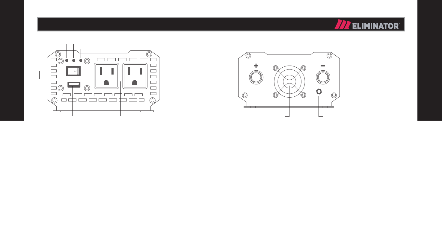
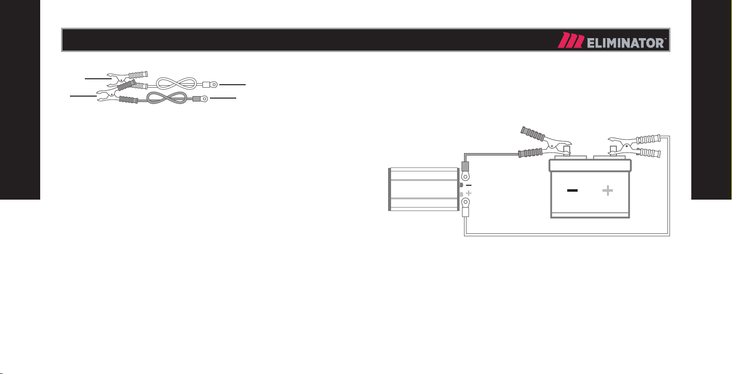
1. Remove the terminal covers from the inverter.
2. Connect the positive (+) connector of battery clamps to positive (+) DC input terminal
(7) of Inverter.
Connect the negative (-) connector of battery clamps to negative (-) DC input terminal
(8) of Inverter.
Connect the red (+) battery clamp to positive (+) terminal of the vehicle battery.
Connect the black (-) battery clamp to negative (-) terminal of the vehicle battery.
Make sure you have good, secure connections.
3. Switch the ON/OFF switch to Position "I". Make certain that the green Operating LED is
lit and the FAULT LED indicator is not lit.
4. Switch the ON/OFF switch to Position "O". The Fault LED may briey “ash”. This is
normal.
The audible alarm may also sound a short “chirp”. This is also normal.
5. Plug the appliance into one of the two AC outlets. Make sure the appliance is off before
plugging it in. Connect devices to USB port for charging (if needed).
6. Turn the inverter on.
7. Turn the appliance on. The appliance should begin working.
8. Observe the LED indicators for normal operation.
Operating Issues
TELEVISION AND AUDIO EQUIPMENT SUGGESTIONS

TROUBLESHOOTING
11 model no. 011-2047-2 | contact us : 1-877-466-8191 12
WARRANTY
TROUBLESHOOTING
PROBLEM: Low or No Output Voltage – Fault LED Lit
Reason Solution
Poor contact with battery, inverter
terminals.
Clean terminals thoroughly. Reinstall
and tighten.
PROBLEM: Inverter Auto Shut Down – Fault LED Lit
Reason Solution
Battery voltage is below 10.0 volts. Charge or replace battery.
Inverter is too hot (thermal shut down
mode).
• Allow inverter to cool.
• C heck for adequate ventilation.
• Reduce the load on the inverter to
the specified TrueRatedTM power
max output.
PROBLEM: Inverter Shut Down – Fault LED Lit
Reason Solution
Equipment being operated draws too
much power.
Do not use the equipment with this
inverter; use a higher wattage inverter.
PROBLEM: No AC Output – Yellow Ground Fault LED Lit
Reason Solution
Ground fault is unintended AC current
that is flowing to ground. It can be
caused by faulty wiring, bad insulation,
very long wiring, and sparking
appliances.
Turn inverter OFF (O) to reset it, then
to ON (I). IF the inverter immediately
shuts off, disconnect each appliance
or wiring until the inverter will stay
on after reset. Examine the wiring or
appliance for unintended connections.
Repair or replace as necessary.
PROBLEM: Continuous Buzzing Sound
Reason Solution
Input voltage is below 10.5 volts. Keep input voltage above 10.5 volts.
Poor or weak battery condition. Recharge or replace battery.
Poor or loose cable connection. Inspect terminals and tighten all connections.
Inadequate power being delivered to
the inverter or excessive voltage drop.
Made in China
Imported by MotoMaster Canada, Toronto, Canada M4S 2B8
Electronic products are known to contain materials that are toxic if improperly
disposed. Contact local authorities for disposal and recycling information.
This MotoMaster®Eliminator®product carries a one (1) year warranty against defects
in workmanship and materials. At its discretion, MotoMaster Canada agrees to have any
defective part(s) repaired or replaced free of charge, within the stated warranty period,
when returned by the original purchaser with proof of purchase. This product is not
guaranteed against wear or breakage due to misuse and/or abuse.
DISPOSAL/RECYCLING OF INVERTER
CONFORMS TO UL STD.458
CERTIFIED TO CSD STD. C22.2 NO.107.1
Table of contents
Other Motomaster Inverter manuals
Popular Inverter manuals by other brands

Scientific
Scientific SMG2000 Series user manual

Growatt
Growatt SPF-3500ES troubleshooting guide

SMA
SMA SUNNY BOY 3.0 operating manual

Hyundai power products
Hyundai power products 1500 quick start guide

Belkin
Belkin F5C400-140W operating instructions

Shihlin electric
Shihlin electric SS2 Series user manual