Determining the maximum load of connected devices
WARNING!
DO NOT overload your power inverter! Overloading the power inverter, even for a
short time, could result in serious damage to the power inverter and/or to the connected device.
A few simple steps are necessary to avoid overloading the power inverter:
• Identify all devices that you would like to power.
• Add up the total wattage of devices that will be powered. The wattage can be found on the individual
device’s rating plate, as well as in the instruction manual.
IMPORTANT!
In some cases, the wattage might not be listed on the devices you want to connect to the
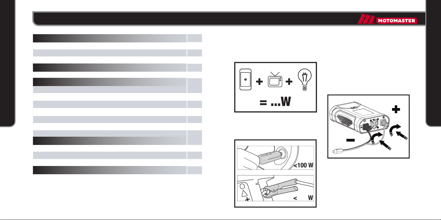
power inverter. In that case, calculate the wattage using the following equation:
VOLTS x AMPERE = WATTS
Formula: 115 Volts x XAmperes = XXXX Watts
Example: 115 Volts x 5Amperes = 600 Watts
CAUTION!
Understand the difference between rated (running) wattage and surge (starting) wattage.
The RATED (RUNNING) WATTAGE is the average amount of power that a device consumes
continuously.
The SURGE (STARTING) WATTAGE is the amount of power that a device consumes at start-
up for a limited period of time (2–3 seconds). Some devices (e.g. induction motors of air
conditioners and refrigerators) may have a start-up surge of 3 to 7 times the rated wattage.
IMPORTANT!
The power inverter can supply momentary surge power that is higher (1500 W) than
its maximum power rating (750 W). Some products with a rated wattage lower than the
maximum power rating for your power inverter may still exceed the power inverter's surge
capability and trigger an overload shutdown.
Products rated with the following power and surge ratings or less can be connected to the
power inverter.
POWER RATING MAXIMUM WATTAGE
5 min max. power rating 750 W
Continuous power rating (RATED WATTAGE) 750 W
Surge rating max. (SURGE WATTAGE) 1500 W
Wattage of commonly used devices
IMPORTANT!
The wattages given below are estimates. The actual wattage required for your devices may
differ from those listed. Be sure to check the specic wattage requirements on the rating
label and in the operating instructions of devices to be used.
IMPORTANT!
Add up the total wattage of devices to be powered.
TAKE INTO CONSIDERATION THE SURGE WATTAGE REQUIRED BY ELECTRICAL MOTORS
AS WELL AS THE RATED WATTAGE.
PRODUCTS
WATTS REQUIRED
PRODUCTS
WATTS REQUIRED
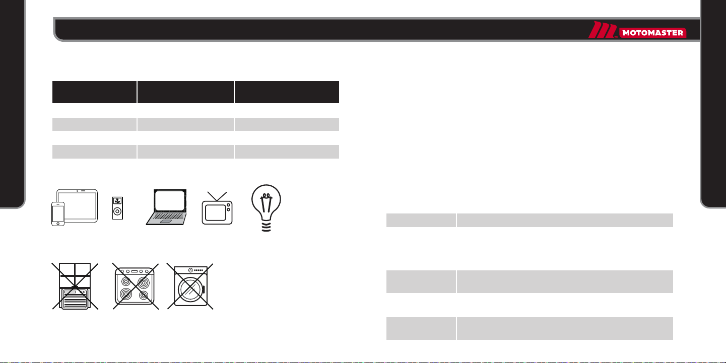
Portable music
MP3 player
Digital camera
Smartphone/Tablet
Laptop computer
13" television
10 W
10 W
10 W
20–30 W
60 W
100 W
Handheld gaming device
27" television
Food processor
Small appliance
Power tool
130 W
280 W
350 W
450 W
600 W
12 model no. 011-1901-4 | contact us: 1-877-466-8191 13
OPERATION
OPERATION