Motomaster Eliminator 11-1913-6 User manual

32
ACCESSORIES
Recommended accessories for use with your tool are available from your
local dealer. If you need assistance regarding accessories, please contact
manufacturer at 1-877-571-2391.
WARNING
The use of any accessory not recommended for use with
this appliance could be hazardous.
SPECIFICATIONS
Boost Ampere 12 V DC, 700 A instantaneous,
On: 5 seconds, 350 A O: 1 minute
Peak Amperage 1400 A
Battery Type Maintenance-free, sealed lead acid,
12 V DC, 21 aH
Area Light 1 long-life white LED
USB Port 3.1 A max., 5 V DC
Compressor Maximum
Pressure
120 PSI
12 V DC Adaptor 12 V DC
011-1913-6
®
MD
®
SPECIFICATIONS
ACCESSORIES
J7C09ME_11-1913_EN_082418.indd 32-1 8/24/2018 11:15:43 AM
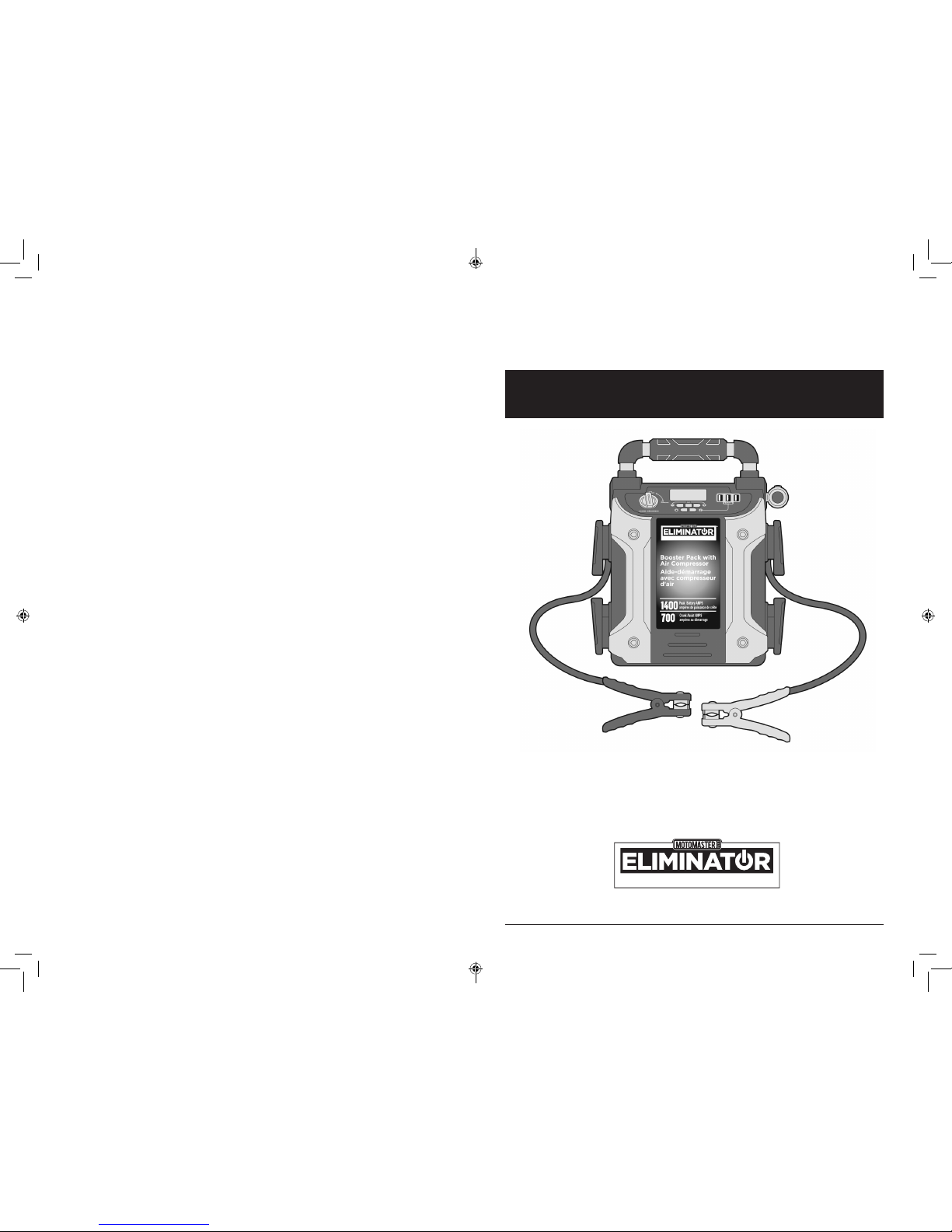
Owner’s Manual
MODEL 1119136
Booster Pack
with Air Compressor
MD
®
J7C09ME_11-1913_EN_082418.indd 2-3 8/24/2018 11:15:43 AM
INTRODUCTION ............................................................................................ 3
SAFETY INFORMATION ............................................................................... 4
General Safety Warnings and Instructions ..................................... 4
FIRST AID .......................................................................................................... 9
PREPARING FOR USE .................................................................................... 10
Controls & Features ................................................................................. 12
Charging with an AC Source ................................................................ 14
Charging with a DC Source................................................................... 14
COMMON ACTIONS AND UNIT RESPONSES ....................................... 15
JUMP-STARTING YOUR VEHICLE............................................................... 17
Negative Grounded Battery.................................................................. 17
Positive Grounded Battery .................................................................... 19
CHARGING A USB DEVICE........................................................................... 22
EMERGENCY AREA LIGHT ........................................................................... 24
USING THE COMPRESSOR........................................................................... 25
TROUBLESHOOTING..................................................................................... 29
MAINTENANCE AND CARE........................................................................ 30
LIMITED WARRANTY..................................................................................... 31
ACCESSORIES .................................................................................................. 32
SPECIFICATIONS............................................................................................. 32
SAVE THESE INSTRUCTIONS.
This manual contains important safety and operating instructions.
Read all instructions and follow them with use of this product.
Questions? Call Customer Service at 1-877-571-2391 for model Model 11-1913-6.
2
TABLE OF CONTENTS
TABLE OF CONTENTS 3
INTRODUCTION
The Booster Pack with Air Compressor is a compact, durable, portable
jump-start system for vehicles that have a standard 12 V battery system.
This self-contained, rechargeable system will start most vehicles without
the need for a host vehicle or a 12 V DC power supply. The built-in 12 V DC
compressor is the ultimate compressor for all vehicle tires, trailer tires and
recreational inatables.
The purpose of this Owner’s Manual is to provide explanations and
procedures on operating, maintaining and troubleshooting the product
to enable you to fully utilize the functions and features it provides, safely
and eectively.
Important
• This unit is delivered in a partially charged state – you must fully
charge it upon purchase and before using it for the rst time.
Initial AC charge should be for 40 hours.
• This unit was designed for HOUSEHOLD USE ONLY.
This Class B digital apparatus complies with Canadian ICES-003. CAN
ICES-3(B)/NMB-3(B).
INTRODUCTION
J7C09ME_11-1913_EN_082418.indd 2-3 8/24/2018 11:15:43 AM
4
SAFETY INFORMATION
The following conventions are used in this guide:
WARNING
Warnings identify conditions that could result in damage to the product or
to other equipment.
CAUTION
Cautions identify conditions or practices that could result in damage to the
product or to other equipment.
Important
These notes describe an important action item or an item that you must
pay attention to.
NOTE
These notes describe additional information which may add to your
understanding of how to use the product.
GENERAL SAFETY WARNINGS AND INSTRUCTIONS
WARNING
General instructions pertaining to a risk of re, electric shock,
burst hazard, or injury to persons or property
• Avoid dangerous environments. Do not use appliances in damp or wet
locations. Do not use appliances in the rain.
• Keep children away. All visitors should be kept at a distance from
work area.
• Dress properly. Do not wear loose clothing or jewellery. They can be
caught in moving parts. Rubber gloves and substantial, non-skid footwear
are recommended when working outdoors. Wear protective hair covering
to contain long hair.
• Use safety glasses and other safety equipment. Use safety goggles
or safety glasses with side shields, complying with applicable safety
standards. Safety glasses or the like are available at extra cost from your
local dealer.
• Store idle appliance indoors. When not in use, appliances should be
stored indoors in a dry, high, or locked-up place – out of reach of children.
SAFETY INFORMATION 5
SAFETY INFORMATION
• Do not abuse cord. Never carry appliance by cord or yank it to
disconnect from receptacle. Keep cord from heat, oil, and sharp edges.
• Disconnect appliances. Disconnect the appliance from the power supply
when not in use, before servicing, and when changing accessories.
• Ground Fault Circuit Interrupter (GFCI) protection should be provided
on the circuits or outlets to be used. Receptacles with built in GFCI
protection are available and may be used for this measure of safety.
• Use of accessories and attachments. The use of any accessory or
attachment not recommended for use with this appliance could be
hazardous. Refer to the accessory section of this manual for further details.
• Stay alert. Watch what you are doing. Use common sense. Do not operate
appliance when you are tired.
• Check for damaged parts. A part that is damaged should be properly
repaired or replaced by an authorized service centre before further use
unless otherwise indicated elsewhere in this instruction manual. Have
defective switches replaced by authorized service centre. Do not use tool if
switch does not turn it on and o.
• Do not operate this appliance near ammable liquids or in gaseous or
explosive atmospheres. Motors in these tools often spark and the sparks
might ignite fumes.
• Do not expose to extreme heat or ames.
• Never immerse the unit in water or any other liquid, or use when wet.
• NEVER ATTEMPT TO USE THE AC AND DC CHARGING METHODS AT
THE SAME TIME.
• NEVER connect this unit to a positive grounded vehicle using the 12 V DC
Charging Adaptor.
• The 12 V DC Charging Adaptor must only be connected to batteries with
a nominal output voltage of 12 volts. The unit will not operate from a 6 V
battery and will sustain permanent damage if connected to a 24 V battery.
Specic Safety Instructions for Jump Starters
WARNING
Specic instructions pertaining to a risk of burst hazard or
explosive gases
• DO NOT use the unit for charging dry-cell batteries that are commonly
used with home appliances. These batteries may burst and cause injury
to persons and damage property. Use the unit for charging/boosting a
lead-acid battery only. It is not intended to supply power to a low-voltage
electrical system other than in a starter-motor application.
SAFETY INFORMATION (cont’d)
J7C09ME_11-1913_EN_082418.indd 4-5 8/24/2018 11:15:43 AM

7
SAFETY INFORMATION
• When using this unit close to the vehicle’s battery and engine, stand the
unit on a at, stable surface, and be sure to keep all clamps, cords, clothing
and body parts away from moving vehicle parts.
• Never allow red and black clamps to touch each other or another common
metal conductor — this could cause damage to the unit and/or create a
sparking/explosion hazard.
• For negative-grounded systems, connect the positive (red) clamp to the
positive ungrounded battery post and the negative (black) clamp to the
vehicle chassis or engine block away from the battery. Do not connect the
clamp to the carburetor, fuel lines or sheet-metal body parts. Connect to a
heavy gauge metal part of the frame or engine block.
• For positive-grounded systems, connect the negative (black) clamp to
the negative ungrounded battery post and the positive (red) clamp to the
vehicle chassis or engine block away from the battery. Do not connect the
clamp to the carburetor, fuel lines or sheet-metal body parts. Connect to a
heavy gauge metal part of the frame or engine block.
• If the clamps are connected incorrectly with regard to polarity, the backlit
LCD screen will display the Battery Status Icon, Battery Voltage Indicator,
and the Clamp Icons. The Alarm Icon, the“+”and ”–” signs and the Reverse
Polarity Icons will ash and the unit will sound a continuous alarm until the
clamps are disconnected. Disconnect the clamps and reconnect to battery
with correct polarity.
• Always disconnect the negative (black) jumper cable rst, followed by the
positive (red) jumper cable, except for positive grounded systems.
• Do not expose battery to re or intense heat since it may explode. Before
disposing of the battery, protect exposed terminals with heavy-duty
electrical tape to prevent shorting (shorting can result in injury or re).
• Place this unit as far away from the battery as cables permit.
• Never allow battery acid to come in contact with this unit.
• Do not operate this unit in a closed area or restrict ventilation in any way.
• This system is designed to be used only on vehicles with a 12 V DC battery
system. Do not connect to a 6 V or 24 V battery system.
• This system is not designed to be used as a replacement for a vehicular
battery. Do not attempt to operate a vehicle that does not have a battery
installed.
• Excessive engine cranking can damage a vehicle’s starter motor. If
the engine fails to start after the recommended number of attempts,
discontinue jump-start procedures and look for other problems that may
need to be corrected.
• Do not use this jump starter on a watercraft. It is not qualied for marine
applications.
• Although this unit contains a non-spillable battery, it is recommended that
unit be kept upright during storage, use and recharging. To avoid possible
6
SAFETY INFORMATION
• Use of an attachment not supplied, recommended or sold by
manufacturer specically for use with this unit may result in a risk of
electrical shock and injury to persons.
• Working in the vicinity of a lead acid battery is dangerous. Batteries
generate explosive gases during normal battery operation. For this reason,
it is of the utmost importance that each time before using the jump-starter
you read this manual and follow instructions exactly.
• To reduce the risk of battery explosion, follow these instructions and
those published by the battery manufacturer and manufacturer of
any equipment you intend to use in the vicinity of the battery. Review
cautionary markings on these products and on the engine.
• This equipment employs parts (switches, relays, etc.) that produce arcs or
sparks. Therefore, if used in a garage or enclosed area, the unit MUST be
placed not less than 18 inches (45.5 cm) above the oor.
• This unit is not for use by children and should only be operated
by adults.
CAUTION
To reduce the risk of injury or property damage
• NEVER ATTEMPT TO JUMP-START OR CHARGE A FROZEN BATTERY.
• Vehicles that have on-board computerized systems may be damaged if
vehicle battery is jump-started. Before jump-starting, read the vehicle’s
owner’s manual to conrm that external-starting assistance is suitable.
• Never smoke or allow a spark or ame in vicinity of vehicle battery, engine
or power station.
• Stay clear of fan blades, belts, pulleys, and other parts that can cause injury
to persons.
• Remove personal metal items such as rings, bracelets, necklaces and
watches when working with a lead acid battery. A lead acid battery can
produce a short circuit current high enough to weld a ring, or similar metal
object, to skin, causing a severe burn.
• Do not wear vinyl clothing when jump-starting a vehicle. Friction can
cause dangerous static-electrical sparks.
• Be extra careful to avoid dropping a metal tool onto the battery. It might
spark or short-circuit the battery or another electrical part and could cause
an explosion.
• Jump-start procedures should only be performed in a safe, dry, well-
ventilated area.
• Always store battery clamps when not in use. Never touch battery clamps
together. This can cause dangerous sparks, power arcing and/or explosion.
SAFETY INFORMATION (cont’d) SAFETY INFORMATION (cont’d)
J7C09ME_11-1913_EN_082418.indd 6-7 8/24/2018 11:15:43 AM

8 9
SAFETY INFORMATION
FIRST AID
CAUTION
To reduce the risk of injury
When working with lead acid batteries, always make sure immediate
assistance is available in case of accident or emergency.
Always have protective eyewear when using this product: contact with
battery acid may cause blindness and/or severe burns. Be aware of rst aid
procedures in case of accidental contact with battery acid.
Have plenty of fresh water and soap nearby in case battery acid contacts
skin.
• Skin: If battery acid comes in contact with skin, rinse immediately with
water, then wash thoroughly with soap and water. If redness, pain, or
irritation occurs, seek immediate medical attention.
• Eyes: If battery acid comes in contact with eyes, ush eyes immediately, for
a minimum of 15 minutes and seek immediate medical attention.
• LCD liquid crystal display: If liquid crystal comes in contact with your
skin: Wash area o completely with plenty of water. Remove contaminated
clothing. If liquid crystal gets into your eye: Flush the aected eye with
clean water and then seek medical attention. If liquid crystal is swallowed:
Flush your mouth thoroughly with water. Drink large quantities of water
and induce vomiting. Then seek medical attention.
damage that may shorten the unit’s working life, protect it from direct
sunlight, direct heat and/or moisture.
• All ON/OFF switches should be in the OFF position when the unit is
charging or not in use. Make sure all switches are in the OFF position
before connecting to a power source or load.
Specic Safety Instructions for the USB Ports
CAUTION
To reduce the risk of property damage
• Do not insert foreign objects into the unit’s USB outlets.
• Do not attach USB hubs or more than one personal electronic device to
each USB Port.
• Do not use this unit to operate appliances that require more than 3.1A (5V)
to operate from each of the USB Ports.
• Some household USB-powered electronics will not operate with this unit.
Specic Safety Instructions for Compressors
WARNING
Specic instructions regarding the risk of bursting
• Bursting articles can cause serious injury.
• Carefully follow instructions on articles to be inated.
• Never exceed the recommended pressure listed in instructions on articles
to be inated. If no pressure is given, contact article manufacturer before
inating.
• Monitor the pressure at all times on the LCD screen.
CAUTION
To reduce the risk of injury or property damage
• Never leave the compressor unattended while in use.
• Do not operate compressor continuously for longer than approximately
10 minutes, depending on ambient temperatures, as it may overheat. This
could damage the compressor. Follow the instructions in the“Portable
Compressor” section.
SAFETY INFORMATION (cont’d) FIRST AID
J7C09ME_11-1913_EN_082418.indd 8-9 8/24/2018 11:15:43 AM

11
PREPARING FOR USE
WARNING
SHOCK HAZARD
• Outdoor use extension cords. When appliance is used outdoors, only use
extension cords intended for outdoor use.
• Extension cords. Make sure your extension cord is in good condition. When
using an extension cord, be sure to use one heavy enough to carry the
current your product will draw. An undersized cord will cause a drop in
line voltage resulting in loss of power and overheating. The following table
shows the correct size to use depending on cord length and nameplate
ampere rating. If in doubt, use the next heavier gauge. The smaller the
gauge number, the heavier the cord.
Length 0-25'
(0-7.6 m)
26'-50'
(7.9-15.2 m)
51'-100'
(15.5-30.4 m)
101'-150'
(30.7-45.7 m)
American
Wire Gauge
(AWG)
18 16 16 14
• If an extension cord is used, make sure that:
–the pins of extension cord are the same number, size and shape
as those in the charger;
–the extension cord is properly wired and in good electrical
condition;
–the wire size is large enough for the AC rating of the charger as
indicated in the table above.
• DO NOT operate unit with damaged cord or plug; or if the unit has
received a sharp blow, been dropped, or otherwise damaged in any way.
Do not disassemble the unit; take it to a qualied service technician when
service or repair is required. Incorrect reassembly may result in a risk of
electric shock or re, and will void warranty.
• Use of an attachment not supplied, recommended or sold by
manufacturer specically for use with this unit may result in a risk of
electric shock and injury to persons.
• NEVER submerge this unit in water; DO NOT expose it to rain, snow or use
when wet.
• To reduce risk of electric shock, disconnect the unit from any power source
before attempting maintenance or cleaning. Turning o controls without
disconnecting will not reduce this risk.
10
PREPARING FOR USE
Lead acid batteries require routine maintenance to ensure a full charge and
long battery life. All batteries lose energy from self-discharge over time and
more rapidly at higher temperatures. Therefore, batteries need periodic
charging to replace energy lost through self-discharge. When the unit is
not in frequent use, manufacturer recommends the battery be recharged at
least every 30 days.
NOTE: Recharging battery after each use will prolong battery life;
frequent heavy discharges between recharges and/or overcharging will
reduce battery life. The battery can be recharged using the built-in 120 V AC
charger.
NOTE: Make sure all other unit functions are turned o during
recharging, as this can slow the recharging process.
Important
This unit is delivered in a partially charged state. Fully charge unit
with a household extension cord (not supplied) for a full 40 hours
before using for the rst time. You cannot overcharge the unit using
the AC charging method.
• To recharge this unit, use only the built-in AC charger.
• All On/O switches should be in the O position when the unit is
charging or not in use. Make sure all switches are in the O position before
connection to a power source or load.
PREPARING FOR USE PREPARING FOR USE (cont’d)
J7C09ME_11-1913_EN_082418.indd 10-11 8/24/2018 11:15:44 AM
PREPARING FOR USE
PREPARING FOR USE
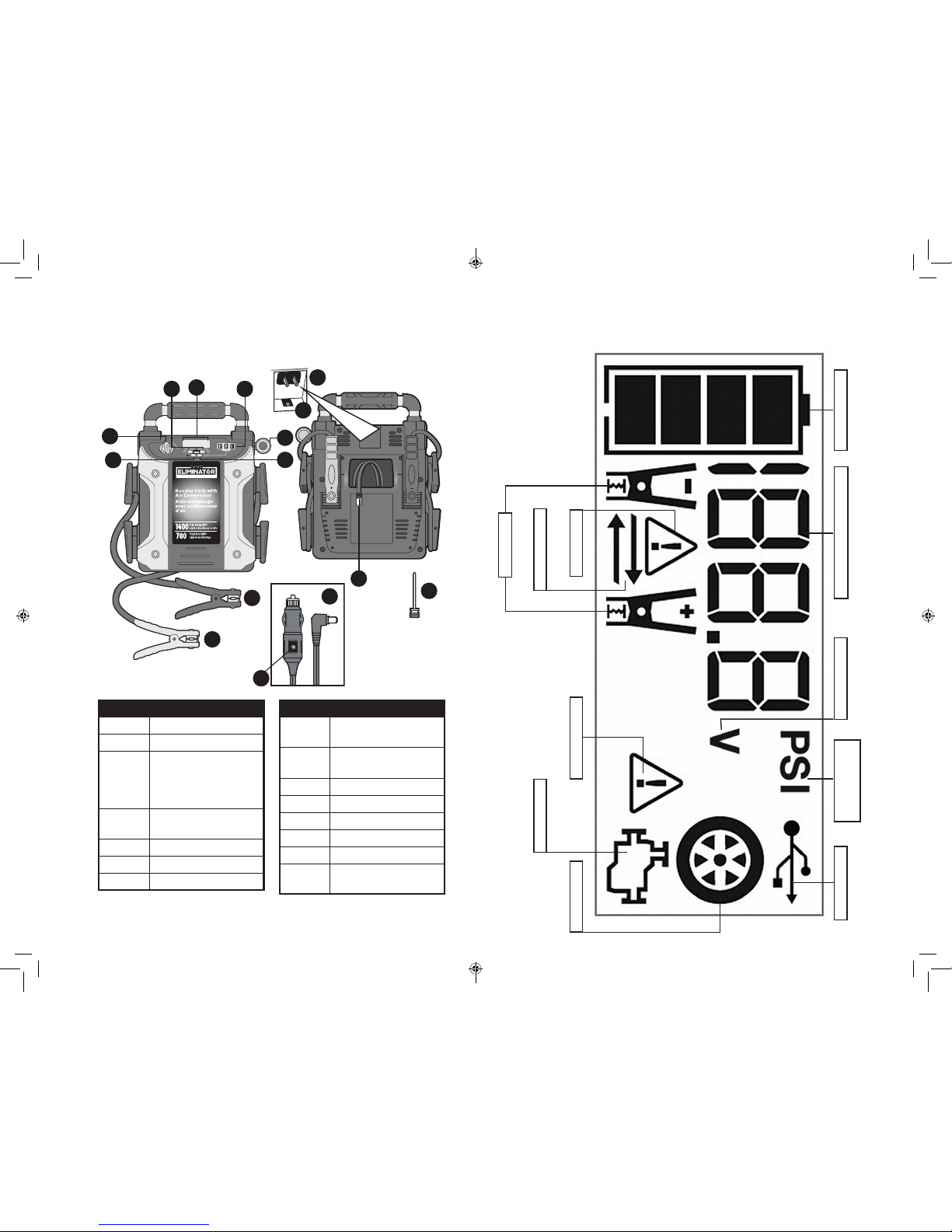
Controls and Features
MD
®
JUMPER/ DÉMARREUR
ON
MARCHE
OFF
ARRÊT
3.1AUSB
AIR
MD
®
1
2
34
6
13
12 11
10
8
7
5
9
14
15
Feature Description
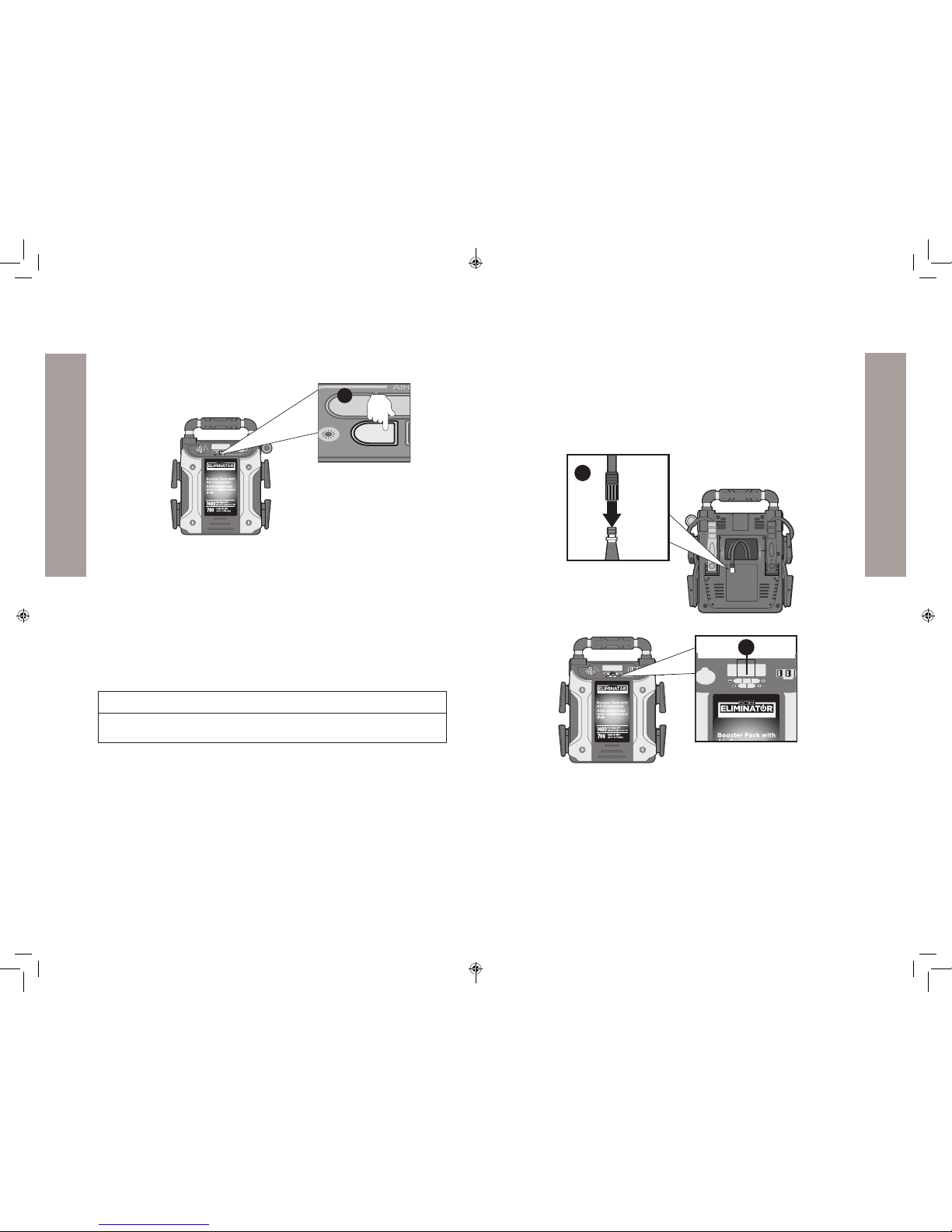
1 Area Light Power Button
2Jump-Starter Power Switch
3Compressor Controls:
Decrease Pressure Control (–),
Power Button, and Increase
Pressure Control (+)
4Backlit LCD Screen (see details
on the next page)
5USB Ports (3)
6Pivoting LED Emergency Light
7USB Power Button
Feature Description
8Built-in 120 Volt AC Charger
(under protective cover)
912 V DC Charging Port (under
protective cover)
10 Air Hose and Sure Fit® Nozzle
11 Needle Adaptor
12 Positive (+) Red Clamp
13 Negative (–) Black Clamp
14 12 V DC Charging Adaptor
15 12 V DC Charging Adaptor LED
Indicator
Battery Status Icon Digital Display (varies by function)
Compressor Pressure
Indicator USB IconVoltage Indicator
Alarm Icon
Reverse Polarity Icons
Fault Icon
Jump Starter Icon
Compressor Icon
Clamp Icons
PREPARING FOR USE (cont’d) PREPARING FOR USE (cont’d) 1312
J7C09ME_11-1913_EN_082418.indd 12-13 8/24/2018 11:15:44 AM

14
PREPARING FOR USE
15
COMMON ACTIONS AND UNIT RESPONSES
Important
• The DC recharging method will NOT recharge the unit as eectively as
recharging from 120 volt AC. Manufacturer suggests that you only use the
12 Volt DC Charging Adaptor if the unit needs to be charged immediately
and no 120 volt power source is available.
• When using a vehicle’s 12 V DC accessory outlet as a power source, be
aware that some vehicles require the ignition be turned on to power the
accessory outlet.
• The LCD screen will not activate when using the 12 volt DC charging
method.
The following actions turn the unit on and activate
the LCD screen:
Press the Area Light
Power Button. (Refer to
the "Emergency Area Light"
section.)
A beep will sound and the Area Light will turn on.The backlight will
turn on for 10 seconds only. The LCD screen will continue to display the
Battery Status Icon and Battery Voltage Indicator. The unit remains on
until the Area Light Power Button is pressed again to turn it o.
Press the USB Power
Button. (Refer to the
"Charging a USB Device"
section.)
A beep will sound and the USB Ports will turn on.The backlight will turn on for
10 seconds only. The LCD screen will display the Battery Status Icon, Battery
Voltage Indicator, and the USB Icon; indicating the three USB Ports are active.
The unit remains on until the USB Power Button is pressed again to turn it o.
Press the Compressor
Power Button. (Refer to
the "Using the Compressor"
section.)
A beep will sound and the backlit LCD screen will display the Battery Status
Icon, "XXX" PSI and the Compressor Icon. If no further actions are taken after
1 minute, the unit will display the Battery Status Icon and Battery Voltage
Indicator for 10 seconds before automatically turning o.
Whenever the clamps
are properly connected
to a battery (refer to
the "Jump-Starting Your
Vehicle" section) ...
... a beep will sound and the backlit LCD screen will display the Battery Status
Icon, Battery Voltage Indicator, the Clamp Icons, and the“+”and ”–”signs.
The Jump Starter Icon will ash.The unit remains on until the clamps are
disconnected from the battery.
If the Jump Starter
Switch has been turned
to the ON position and
the clamps are not
connected to a battery
(refer to the "Jump-Starting
Your Vehicle" section) ...
... a two-second warning will sound every 10 seconds.The backlit LCD screen
will display the Battery Status Icon, BatteryVoltage Indicator, the Clamp Icons,
and the“+”and ”–”signs.The Alarm Icon and the Jump Starter Icon will ash.
The unit remains on until the Jump Starter Power Switch is switched o and
then displays the battery status icon and the voltage of digital display for 10
seconds before automatic shut down.
Charging with an AC Source
Pull open the AC adaptor cover located on the back of the unit.
Connect an extension cord to the unit. (Extension cord not included.)
Plug the other end of the cord into a standard 120 V AC wall outlet.
When the unit is properly connected to an AC power source, the LCD
screen will display the following:
The bars on the Battery Status Icon represent the charge level of the
unit’s internal battery. The bars on the Battery Status Icon will change
from empty to solid (bottom to top) repeatedly to indicate the unit is
charging. The backlight will turn on for 10 seconds only.
Charge for approximately 40 hours or until the Battery Status Icon
shows 4 solid bars.
When charging is complete, unplug the AC extension cord from the AC
outlet and then disconnect it from the unit.
NOTE: The unit cannot be overcharged using this method.
Charging with a DC Source
Lift the protective cover of the Built-in 120 V AC Charger located on the
back of the unit. Make sure the AC extension cord is disconnected from
the 120 V AC Charger.
Insert the barrel tip of the 12 V DC Charging Adaptor into the 12 V DC
Charging Port on the back of the unit.
Insert the grooved tip of the 12 V DC Charging Adaptor into the
vehicle’s 12 V DC accessory outlet or other functioning 12 V DC power
source. The 12V DC Charging Adapter LED Indicator will light to
indicate the unit is properly plugged into the 12V DC power source and
is in charging.
Charge the unit until the Battery Status Icon shows 4 solid bars when
either the Area Light, USB or Compressor Power Button is pressed (with
the adapter unplugged from the unit).
When charging is complete, remove the DC Charging Adaptor from the
unit and the 12 V DC power source when not in use and store in a safe
place.
PREPARING FOR USE (cont’d) COMMON ACTIONS AND UNIT RESPONSES
J7C09ME_11-1913_EN_082418.indd 14-15 8/24/2018 11:15:44 AM
16 17
COMMON ACTIONS AND UNIT RESPONSES
JUMPSTARTING YOUR VEHICLE
Negative Grounded Battery
++–
+
+–
MD
®
JUMPER/DÉMARREUR
ON
MARCHE
OFF
ARRÊT
3.1AUSB
AIR
MD
®
3
4
The following actions turn the unit on and activate
the LCD screen:
If the clamp connections
to the battery’s positive
and negative terminals
are reversed (refer to
the "Jump-Starting Your
Vehicle" section) ...
... the backlit LCD screen will display the Battery Status Icon, Battery Voltage
Indicator, and the Clamp Icons. The Alarm Icon, the“+”and ”–”signs and the
Reverse Polarity Icons will ash and the unit will sound a warning continuously
until the clamps are disconnected from the battery.
If the red and black
clamps touch each other
(refer to the “Jump-Starting
Your Vehicle” section) ...
... the backlit LCD screen will display the Battery Status Icon and Battery
Voltage Indicator. The Clamp Icons,“+”and ”–”signs and the Alarm Icon
will ash. The unit will sound a two-second warning every ten seconds
continuously until the clamps are separated.
When the unit is
charging or recharging
using the built-in 120
Volt AC Charger (refer to
the "Preparing For Use"
section) ...
… a beep will sound and the backlight will turn on for 10 seconds only.The
LCD screen will continue to display the Battery Status Icon and Battery Voltage
Indicator. The bars on the Battery Status Icon will change from empty to solid
(bottom to top) repeatedly.
Viewing Battery Status
The Battery Status Icon and Battery Voltage Indicator indicate the battery
charge level as follows:
• If the battery charge level is at full capacity, four solid bars will display.
• If the battery is partially charged, two or three solid bars will display.
• If the battery is nearly empty, one solid bar will display. The unit should be
charged at this time.
• If the battery is completely empty, four blank bars will display. The unit
MUST be charged at this time or the unit’s built-in low voltage protection
will activate. The empty Battery Status Icon will ash for a short period
of time before automatic shut down. The unit will not operate until the
battery is recharged.
COMMON ACTIONS AND UNIT RESPONSES (cont’d) JUMPSTARTING YOUR VEHICLE
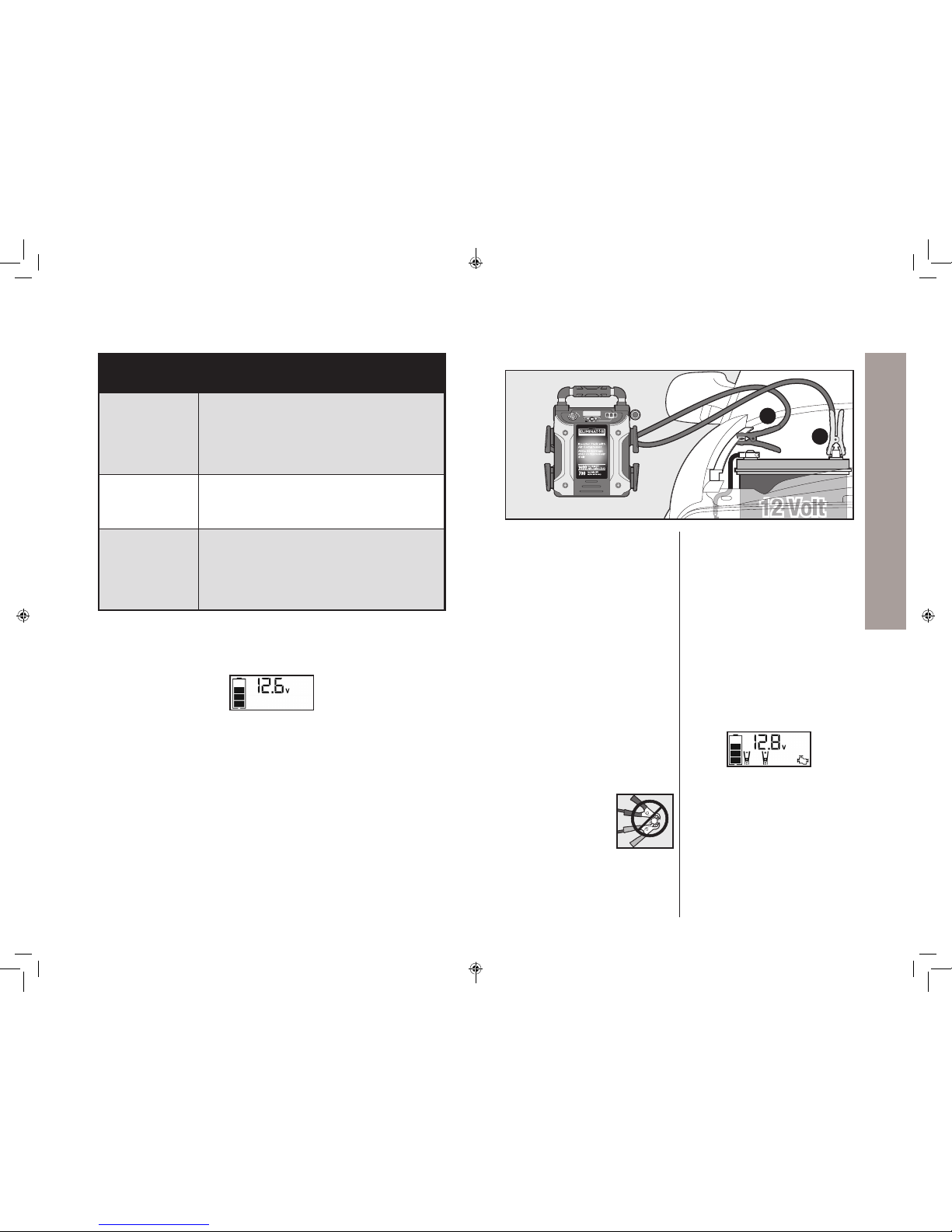
Turn o vehicle ignition and all
accessories (radio, A/C, lights,
connected cell phone chargers,
etc.), put vehicle in“park” and
set emergency brake.
Make sure the Jump-Starter
Power Switch is turned to OFF.
IMPORTANT – To reduce the risk of
a spark near battery:
• Stay clear of fan blades, pulleys,
and other parts that can cause
injury.
• Check polarity of battery posts.
A positive (POS, P, +) battery post
usually has a larger diameter than
a negative (NEG, N, –) battery
post.
• Remove jumper clamps from
clamp tabs.
NEVER allow the DC
output clamps to touch
each other. This may
cause a spark.
Connect the positive (red)
clamp from battery booster to a
positive (POS, P, +) ungrounded
post of the battery.
Connect the negative (black)
clamp from the battery booster
to vehicle chassis (must be a
heavy gauge metal part
of the frame) or engine
block away from the battery.
DO NOT connect the clamp to
carburetor, fuel lines, or sheet
metal body parts.
When the clamps are
connected properly, the backlit
LCD screen will display the
following to indicate the unit is
ready to jump-start:
The Battery Status icon, Battery
Voltage Indicator, Clamp Icons
and the “+” and”–” signs light
solid. The jump starter icon will
ash to indicate the clamps are
properly connected.
Turn the Jump-Starter Power
Switch on.
J7C09ME_11-1913_EN_082418.indd 16-17 8/24/2018 11:15:45 AM

19
JUMPSTARTING YOUR VEHICLE
Positive Grounded Battery
++–
+
+–
MD
®
JUMPER/DÉMARREUR
ON
MARCHE
OFF
ARRÊT
3.1AUSB
AIR
3
4
18
JUMPSTARTING YOUR VEHICLE
WARNING
A SPARK NEAR A BATTERY MAY CAUSE A BATTERY EXPLOSION.
Important
Make sure the Compressor Power Button has been turned OFF before
attempting to use the unit as a Jump-Starter.
JUMPSTARTING YOUR VEHICLE (cont’d) JUMPSTARTING YOUR VEHICLE (cont’d)
Turn o vehicle ignition and all
accessories (radio, A/C, lights,
connected cell phone chargers,
etc.), put vehicle in“park” and
set emergency brake.
Make sure the Jump-Starter
Power Switch is turned to OFF.
IMPORTANT – To reduce the risk of
a spark near battery:
• Stay clear of fan blades, pulleys,
and other parts that can cause
injury.
• Check polarity of battery posts.
A positive (POS, P, +) battery post
usually has a larger diameter than
a negative (NEG, N, –) battery
post.
• Remove jumper clamps from
clamp tabs.
NEVER allow the DC
output clamps to touch
each other. This may
cause a spark.
Connect the negative (black)
clamp from the battery
booster to the negative (NEG,
N, -) ungrounded post of the
battery.
Connect the positive (red)
clamp from battery booster to
the vehicle chassis (must be
a heavy gauge metal part
of the frame) or engine block
away from the battery.
DO NOT connect the clamp
to carburetor, fuel lines or
sheet metal body parts.
When the clamps are
connected properly, the backlit
LCD screen will display the
following to indicate the unit is
ready to jump-start:
The Battery Status icon, Battery
Voltage Indicator, Clamp Icons
and the “+” and”–” signs light
solid. The jump starter icon will
ash to indicate the clamps are
properly connected.
Turn the Jump-Starter Power
Switch on.
.
Turn on ignition switch and
crank the engine in 5-6 second
bursts until engine starts. The
backlit LCD screen will display
the following:
The Battery Status Icon, the
Battery Voltage Indicator, Jump
Starter Icon, Clamp Icons and
the “+” and”–” signs light solid
to indicate the unit is jump-
starting.
Turn the Jump-Starter Power
Switch back to the OFF
position. Disconnect the
negative (–) clamp rst, then
disconnect the positive (+)
clamp.
Important
Always turn the unit o when
not in use. Recharge this unit
fully after each use.
J7C09ME_11-1913_EN_082418.indd 18-19 8/24/2018 11:15:45 AM
21
WARNING
To reduce the risk of injury or property damage
• Follow all safety instructions found in the “Specic Safety Instructions
for Jump Starters”section of this instruction manual.
• Never touch red and black clamps together. This can cause dangerous
sparks, power arcing, and/or explosion.
• If the clamps are connected incorrectly with regard to polarity, the unit
will sound a continuous alarm until the clamps are disconnected. The
backlit LCD Screen will display the Battery Status Icon, the Battery Voltage
Indicator and the Clamp Icons. The“+” and”–” signs above the Clamp Icons,
the Arrow Icons and the Alarm Icon will ash. The backlit LCD screen will
display the following:
CAUTION
To reduce the risk of injury or property damage
• The unit will suer permanent damage if the Jump Starter Power Switch
is turned on while the clamps connected with reverse polarity. Disconnect
the clamps and reconnect to battery with correct polarity.
• If the Jump Starter Power Switch is turned on and the unit detects that the
clamps are not connected to a battery, a two-second warning will sound
every 10 seconds. The LCD screen will display the Battery Status Icon, the
Battery Voltage Indicator, and the Clamp Icons with the“+” and”–” signs.
The Alarm Icon and the Jump Starter Icon will ash. The backlit LCD screen
will display the following :
Turn o the Jump Starter Power Switch; connect the clamps to the battery,
making sure the clamps are connected with correct polarity; then turn the
Jump Starter Power Switch back on.
• Vehicles that have on-board computerized systems may be damaged if
vehicle battery is jump-started. Before jump-starting this type of vehicle,
read the vehicle manual to conrm that external-starting assistance is
advised.
• Excessive engine cranking can damage the vehicle‘s starter motor. If
the engine fails to start after the recommended number of attempts,
20
WARNING
A SPARK NEAR A BATTERY MAY CAUSE A BATTERY EXPLOSION.
Important
Make sure the Compressor Power Button has been turned OFF before
attempting to use the unit as a Jump-Starter.
Turn on ignition switch and
crank the engine in 5-6 second
bursts until engine starts. The
backlit LCD screen will display
the following:
The Battery Status Icon, the
Battery Voltage Indicator, Jump
Starter Icon, Clamp Icons and
the “+” and”–” signs light solid
to indicate the unit is jump-
starting.
Turn the Jump-Starter Power
Switch back to the OFF
position. Disconnect the
positive (+) clamp rst, then
disconnect the negative (–)
clamp.
Important
Always turn the unit o when
not in use. Recharge this unit
fully after each use.
JUMPSTARTING YOUR VEHICLE
JUMPSTARTING YOUR VEHICLE (cont’d)
JUMPSTARTING YOUR VEHICLE
JUMPSTARTING YOUR VEHICLE (cont’d)
J7C09ME_11-1913_EN_082418.indd 20-21 8/24/2018 11:15:46 AM
22 23
USB PORTS
–Allow the unit to cool down for several minutes before
attempting to use the USB Ports again.
–If a fault occurs again, make sure that the total draw of the USB
device plugged into the USB Port does not exceed 3.1A (5V).
–If an individual USB device is within specications and the fault
occurs, have the USB device checked for malfunction and do not
continue to use it with these USB Ports.
• This unit’s USB Ports do not support data communication. They only
provide power to external USB-powered devices. The USB Ports provide
3.1 A (5 V) each.
• Some household USB-powered electronics will not operate with this unit.
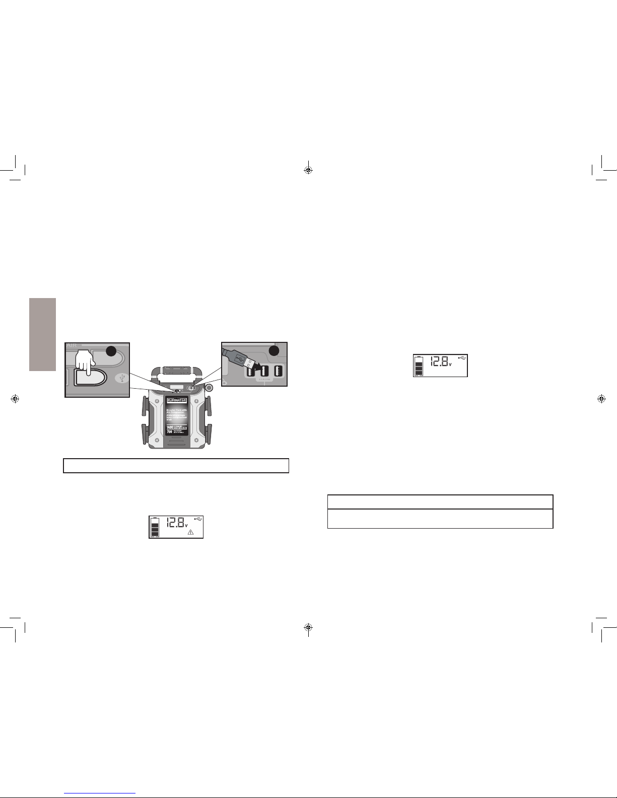
Press the USB Power Button to turn on all of the USB Ports. A beep will
sound. The backlight will turn on for 10 seconds only. The backlit LCD
screen will continuously display the following:
The Battery Status Icon and Battery Voltage Indicator will light solid, as
well as the USB Icon, indicating the USB ports are ready to use.
Plug the USB-powered device into the USB power port(s) and operate
normally.
Press the USB Power Button again to turn o the USB Ports.
Periodically check the unit’s battery status on the backlit LCD screen. Four
solid bars in the battery icon indicates a full battery. When the battery
level is nearly empty with only one solid bar or completely empty with 4
empty bars, the unit must be recharged at this time or the unit’s built-in low
voltage protection will activate. The empty Battery Status Icon will ash for
a short period of time before automatic shut down.
Important
Make sure the USB Ports are turned o when the unit is being recharged
or stored.
discontinue jump-start procedure and look for other problems that need
to be corrected.
• If vehicle fails to start, turn o the ignition, turn o the Jump-Starter Power
Switch, disconnect the jump-start system’s leads and contact a qualied
technician to investigate why the engine did not start.
CHARGING A USB DEVICE
This product’s USB power output is designed to power or charge small to
medium sized devices (e.g. smartphones, MP3 players, etc.). The three USB
Ports provide 3.1A (5V) each.
MD
®
JUMPER/DÉMARREUR
ON
MARCHE
OFF
ARRÊT
3.1AUSB
AIR
3.1A USB
AIR
AIR
12
Important Notes
• When the USB Ports are in use, the unit will monitor for the following
USB fault conditions on all the USB Ports: low battery voltage fault,
overload and short circuit. In any of these cases, the backlit LCD screen will
continuously display the following:
The Fault Icon will ash. The USB Ports will automatically shut down.
Should this occur:
–Disconnect the USB-powered device and press the USB Power
Button again to turn o the USB Ports immediately.
–Make sure the unit does not need to be recharged.
JUMPSTARTING YOUR VEHICLE (cont’d) USB PORTS
USB PORTS
J7C09ME_11-1913_EN_082418.indd 22-23 8/24/2018 11:15:46 AM
24 25
EMERGENCY AREA LIGHT
USING THE COMPRESSOR
The built-in 12 volt DC compressor is the ultimate compressor for all
vehicle tires, trailer tires and recreational inatables. A needle adaptor is
supplied that screws onto the end of the Sure Fit® nozzle at the free end
of the compressor hose. The compressor hose with tire tting is stored in
the compressor hose storage compartment. The Compressor Power Button
and Increase (+) and Decrease (–) Compressor Pressure Control Buttons are
located on the control panel on the front of the unit.
MD
®
JUMPER/DÉMARREUR
ON
MARCHE
OFF
ARRÊT
3.1AUSB
AIR
MD
®
1
MD
®
JUMPER/ DÉMARREUR
ON
MARCHE
OFF
ARRÊT
3.1AUSB
AIR
2
BEFORE PROCEEDING, check the unit’s battery status on the LCD screen.
Four solid bars in the battery icon indicates a full battery. When the battery
level is nearly empty with only one solid bar, the unit MUST be recharged
before use or the unit’s built-in low voltage protection will activate. The
empty Battery Status Icon will ash for a short period of time before
automatic shut down.
The compressor is capable of inating up to 120 pounds per square inch
(PSI) pressure. The compressor can operate long enough to ll up to 3
average sized tires before the battery must be recharged. Return hose to
the storage compartment after use.
The Emergency Area Light is controlled by the Area Light Power Button on
front of the unit.
MD
®
JUMPER/DÉMARREUR
ON
MARCHE
OFF
ARRÊT
3.1AUSB
AIR
MD
®
MD
®
ON
MARCHE
3.1A USB
AIR
1
When the Area Light Power Button is pressed to turn it on, a beep will
sound. The backlit LCD screen will turn on for 10 seconds only and will
then continuously display the Battery Status Icon and the Battery Voltage
Indicator.
Periodically check the unit’s battery status on the backlit LCD screen. Four
solid bars in the battery icon indicates a full battery. When the battery level
is nearly empty with only one solid bar or completely empty with four
empty bars, the unit must be recharged at this time or the unit’s built-in low
voltage protection will activate. The empty Battery Status Icon will ash for
a short period of time before automatic shut down.
Important
Make sure the Emergency Area Light is turned o when the unit is being
recharged or stored.
EMERGENCY AREA LIGHT USING THE COMPRESSOR
J7C09ME_11-1913_EN_082418.indd 24-25 8/24/2018 11:15:47 AM
27
USING THE COMPRESSOR
Inating Tires or Products With Valve Stems
Screw the Sure Fit® nozzle onto the valve stem. Do not overtighten.
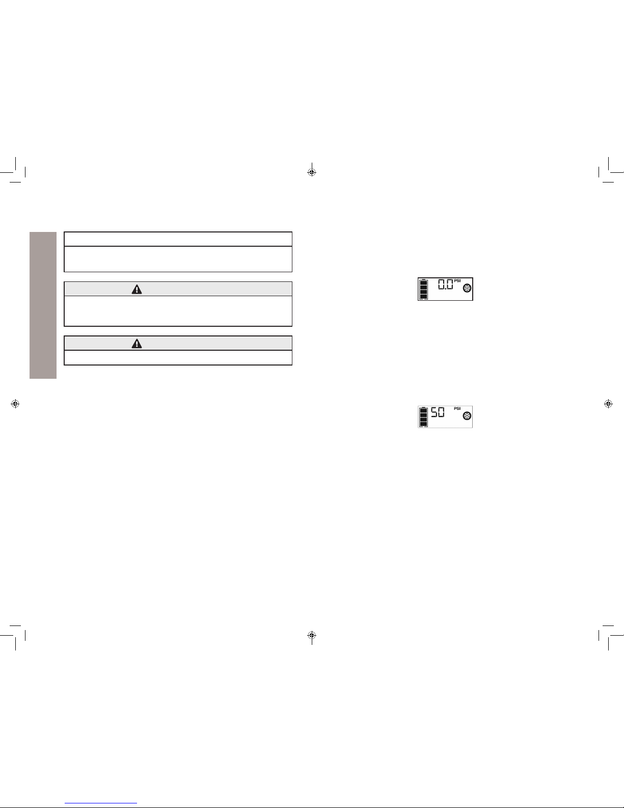
Press the Compressor Power Button. A beep will sound and the backlit
LCD screen will display the following:
The Compressor Icon will light and the digital display will alternately
show the ashing pre-set PSI value (that was last set by the compressor
pressure control buttons) and the current pressure of the item being
inated (which will light solid).
Press the“+” and “–” Pressure Control Buttons to set the desired
pressure from a range pre-set values (between 1 and 120), which will
display on the backlit LCD screen. The unit will sound a beep with
each press of the buttons (holding the button speeds up the upward
or downward value selection). Once the desired pressure has been
entered, release the button and the ashing digital display will show
the new selected pressure, as follows:
The new selected value is now stored in the unit’s memory until it is
manually reset.
Press the Compressor Power Button once more to begin inating.
The Compressor Icon will ash and the digital display will only show
the current pressure value (which will light solid) to indicate the
compressor is activated. Monitor the pressure on the LCD screen.
IMPORTANT NOTE: To interrupt during ination, press the Compressor
Power Button again.
When desired pre-set pressure is reached, the compressor will
automatically stop.
Press the Compressor Power Button again to turn o the unit.
Unscrew and remove the Sure Fit® nozzle from the valve stem.
Allow the unit to cool, then recharge before storing away.
Store the compressor hose and Sure Fit® nozzle in storage
compartment.
26
USING THE COMPRESSOR
Important
Make sure the Jump-Starter Power Switch has been turned OFF before
attempting to use the unit as a Compressor.
WARNING
To reduce the risk of serious injury or property damage,
follow all safety instructions found in the“Specic Safety
Instructions for Compressors”section of this instruction manual.
CAUTION
To reduce the risk of injury or property damage
When the compressor is operated at a low PSI, the unit may start in low and
gradually rev up. When the compressor is operated at higher PSIs, the unit
may operate normally for several minutes, then rev down for a few minutes
before returning to normal operation.
This feature protects the unit from overheating during normal use. In any
event, do not operate compressor continuously for longer than 10 minutes,
as it may overheat. This could damage the compressor.
If the compressor must be operated for longer periods: every 10 minutes
press the Compressor Power Button to turn the compressor o, then restart
after a cooling down period of approximately 30 minutes.
USING THE COMPRESSOR (cont’d) USING THE COMPRESSOR (cont’d)
J7C09ME_11-1913_EN_082418.indd 26-27 8/24/2018 11:15:47 AM
29
TROUBLESHOOTING
Condition Solution
Unit will not
charge
Make sure all of the unit’s functions are turned o.
Make sure a suitable gauge extension cord is properly connected to both the
unit and a functioning AC outlet.
Unit fails to
jump-start
Make sure the unit is not being operated in the Compressor mode.
Make sure unit’s Jump-Starter Power Switch is in the ON position.
Make sure a proper polarity cable connection has been established.
Check that unit has a full charge. Recharge unit if necessary.
USB power port
will not power
appliance
Make sure the USB charging port power button has been pressed.
If a fault condition exists in any of the USB Ports, the Fault Icon on the LCD
screen will ash. Refer to the Important Notes in the“Charging a USB Device”
section to remedy any faults.
Some USB-powered household electronics will not operate with this USB
charging/power port. Check the manual of the corresponding electronic device
to conrm that it can be used with this type of USB charging/power port.
Make sure that the total draw the USB device plugged into the USB Port does
not exceed 3.1A (5V).
Check that unit has a full charge. Recharge unit if necessary.
LED area light
does not come on
Make sure the LED area light power buttonhas been pressed.
Check that unit has a full charge. Recharge the unit if necessary.
Built-in
compressor will
not inflate
Make sure the unit is not being operated in the Jump-Starter mode.
Make sure the compressor power button has been pressed to turn the
compressor on.
Make sure the Sure Fit® nozzle connector is securely screwed on to the valve
stem when attempting to inate tires; or that the needle adaptor is securely
screwed into the Sure Fit® nozzle connector and is inserted properly into the
item to be inated on all other inatables.
The compressor may be overheated. Press the compressor power button to turn the
compressor o. Restart after a cooling down period of approximately 30 minutes.
Check that unit has a full charge. Recharge unit if necessary.
28
USING THE COMPRESSOR
Inating Other Inatables Without Valve Stems
1
Ination of other items requires use of the needle adaptor. Screw the
needle adaptor into the Sure Fit® nozzle. Do not overtighten.
Insert the needle adaptor into item to be inated.
Follow steps 2 through 4 of the “Inating Tires or Products With Valve
Stems” section.
IMPORTANT NOTE: Small items such as volleyballs, footballs, etc.
inate very rapidly. Keep this in mind when setting pressure. Take extra
care not to over-inate.
When the desired pressure is reached, the compressor will
automatically stop. Press the Compressor Power Button again to turn
o the unit.
Disconnect the adaptor from the inated item.
Unscrew and remove the needle adaptor from the Sure Fit® nozzle.
Allow the unit to cool, then recharge before storing away.
Store the compressor hose, Sure Fit® nozzle and needle adaptor in the
storage compartment when not in use.
USING THE COMPRESSOR (cont’d) TROUBLESHOOTING
J7C09ME_11-1913_EN_082418.indd 28-29 8/24/2018 11:15:47 AM

31
MotoMaster® MAKES THIS LIMITED WARRANTY TO THE ORIGINAL
RETAIL PURCHASER OF THIS PRODUCT. THIS LIMITED WARRANTY IS NOT
TRANSFERABLE OR ASSIGNABLE.
MotoMaster® warrants this battery booster for 1 year from the date of
purchase at retail against defective material or workmanship that may
occur under normal use and care. If your unit is not free from defective
material or workmanship, the Manufacturer’s obligation under this warranty
is solely to repair or replace your product with a new or reconditioned unit
at the option of the Manufacturer. It is the obligation of the purchaser to
forward the unit, along with proof of purchase and mailing charges prepaid
to the Manufacturer or its authorized representatives in order for repair or
replacement to occur.
The Manufacturer does not provide any warranty for any accessories
used with this product that are not manufactured by MotoMaster® and
approved for use with this product. This Limited Warranty is void if the
product is misused, subjected to careless handling, repaired, or modied
by anyone other than the Manufacturer or if this unit is resold through an
unauthorized retailer.
The Manufacturer makes no other warranties, including, but not limited
to, express, implied or statutory warranties, including without limitation,
any implied warranty of merchantability or implied warranty of tness for
a particular purpose. Further, the Manufacturer shall not be liable for any
incidental, special or consequential damage claims incurred by purchasers,
users or others associated with this product, including, but not limited to,
lost prots or revenues, anticipated sales, business opportunities, goodwill,
business interruption and any other injury or damage. Any and all such
warranties, other than the limited warranty included herein, are hereby
expressly disclaimed and excluded. Some provinces do not allow the
exclusion or limitation of incidental or consequential damages or length of
implied warranty, so the above limitations or exclusions may not apply to
you. This warranty gives you specic legal rights and it is possible you may
have other rights which vary from this warranty.
THIS LIMITED WARRANTY IS THE ONLY EXPRESS LIMITED WARRANTY
AND THE MANUFACTURER NEITHER ASSUMES NOR AUTHORIZES
ANYONE TO ASSUME OR MAKE ANY OTHER OBLIGATION TOWARDS THE
PRODUCT OTHER THAN THIS WARRANTY.
DO NOT RETURN THIS PRODUCT TO THE STORE!
Whether you need technical advice, repair, or genuine factory
replacement parts, call Customer Service for Assistance: 1-877-571-2391
30
MAINTENANCE AND CARE
All batteries lose energy from self-discharge over time and more rapidly at
higher temperatures. When the unit is not in use, we recommend that the
battery be charged at least every 30 days.
Never submerge the unit in water. If the unit gets dirty, gently clean the
outer surfaces of the unit with a soft cloth moistened with a mild solution of
water and detergent.
Except for the fuse in the 12 V DC Charging Adaptor, there are no
user-replaceable parts. Periodically inspect the condition of adaptors,
connectors, and wires. Contact manufacturer to replace any components
that have become worn or broken.
Battery Replacement/Disposal
The battery should last the service life of the unit. Contact manufacturer for
any information you may need.
Contains a maintenance-free, sealed, non-spillable, lead acid battery,
which must be disposed of properly. Recycling is required, contact your
local authority for information. Failure to comply with local, provincial, and
federal regulations can result in nes or imprisonment. Contact your local
waste management authority to dispose of this product.
WARNING
• Do not dispose of the battery in re as this may result in an explosion.
• Before disposing of the battery, protect exposed terminals with
heavy-duty electrical tape to prevent shorting (shorting can result in
injury or re).
• Do not expose battery to re or intense heat as it may explode.
12 volt DC Adaptor plug fuse replacement
The fuse in the plug end of the 12 V DC Adaptor protects the adaptor’s
charging circuit. If the built-in 120 V AC Charger operates, but the DC
charging adaptor does not, then this fuse may be opened (blown). To
replace the fuse:
• Unscrew the end cap of the DC plug (counterclockwise).
• Remove spring center contact and fuse.
• Check fuse with a continuity checker.
• If blown, locate a replacement 2 amp fuse.
• Replace the fuse, spring, contact and end cap.
• Screw end cap clockwise until it is nger tight – DO NOT OVER-TIGHTEN.
• Test for proper operation of the 12 V DC charging adaptor.
MAINTENANCE AND CARE
LIMITED WARRANTY
LIMITED WARRANTY
J7C09ME_11-1913_EN_082418.indd 30-31 8/24/2018 11:15:47 AM
Table of contents
Other Motomaster Remote Starter manuals


