Motor City Wash Works CROSS-OVER WRAPCHYD03 Series User manual

© Motor City Wash Works, Inc. 48285 Frank, Wixom Michigan 48393 U.S.A. Phone: 248.313.0272 ▪ Fax: 248. 313.0271
8MANLWRPCROVR01 09-16-20 www.motorcitywashworks.com 1
CROSS-OVER™ INSTALLATION MANUAL
Part # WRAPCHYD[ . . . . . ]03
WRAPCELE[ . . . . . ]03
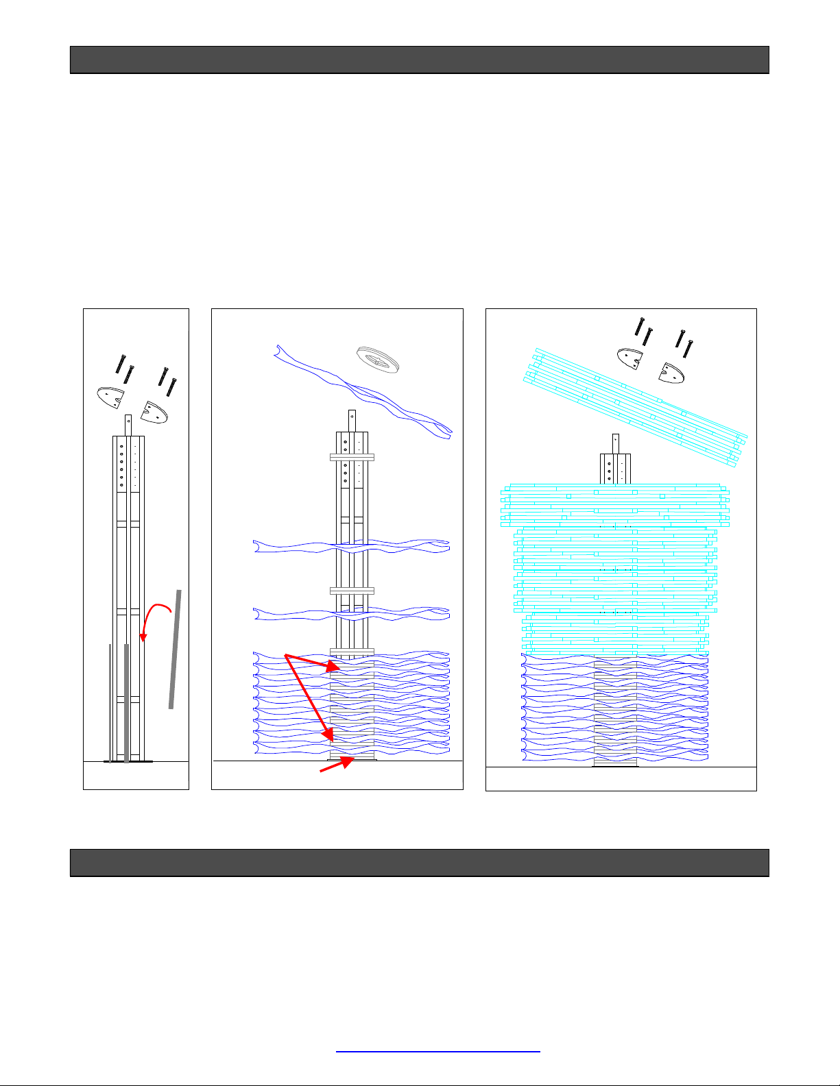
FOR COTTON CLOTH™, STAR FOAM or C-CHANNEL FOAM BRUSHES
TABLE OF CONTENTS
Equipment Utilities Page: 1
Equipment Specifications Page: 1
Suggested Tools and Installation Materials Page: 2
Installation Instructions Page: 2
Electrical Installation Page: 12
Pneumatic Installation Page: 17
Optional Retract Air Panel Installation Page: 18
Optional Mirror Bump Air Panel Installation Page: 20
Foamer Installation Page: 22
Water Feed Installation Page: 23
Hydraulic Installation Page: 24
Start-Up Procedures Page: 25
Operation Page: 28
License Plate Adjustment Page: 33
Maintenance Page: 40
Troubleshooting………………………………………………………………………………………………………..Page: 43
Exploded Views………………………………………………………………………………………………………..Page: 47
Warranty………………………………………………………………………………………………………………..Page: 61
Equipment Utilities
Equipment Specifications and Features
Convenient 115VAC Single Phase Supply Minimizes Installation Cost
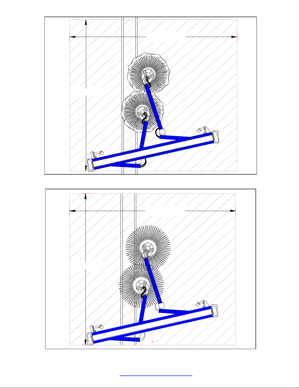
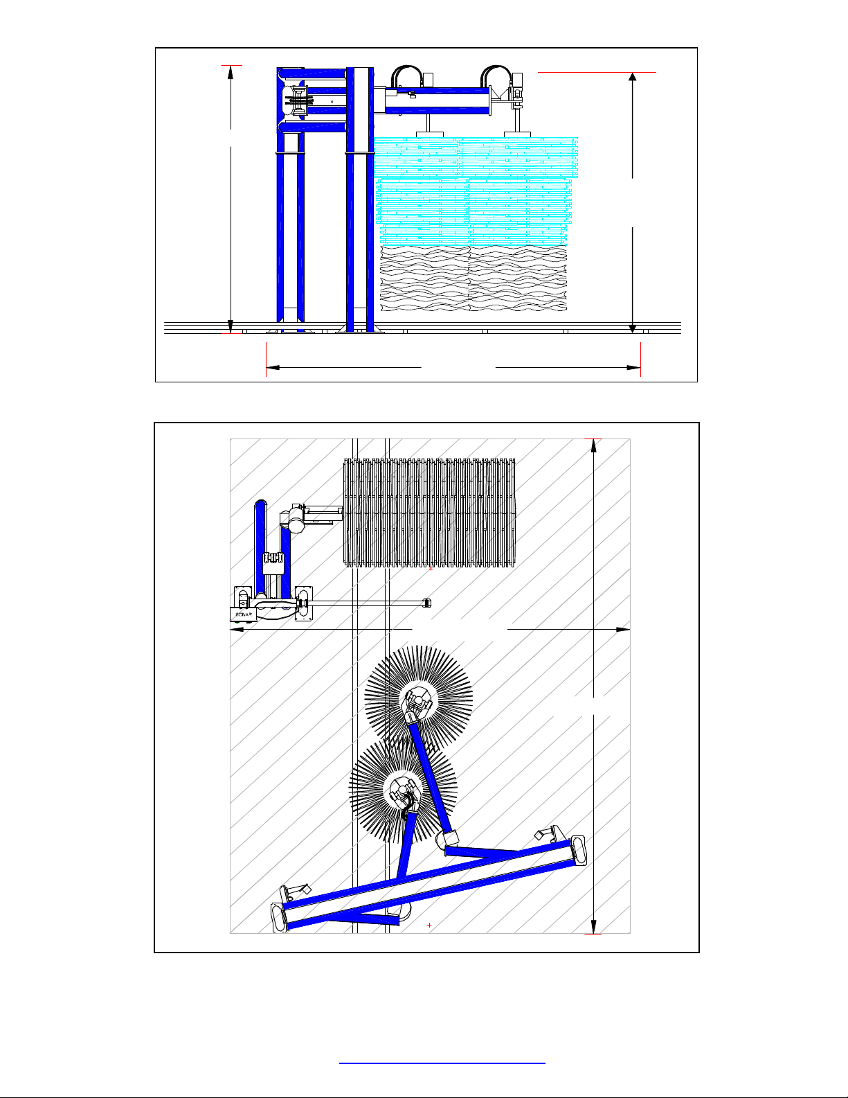
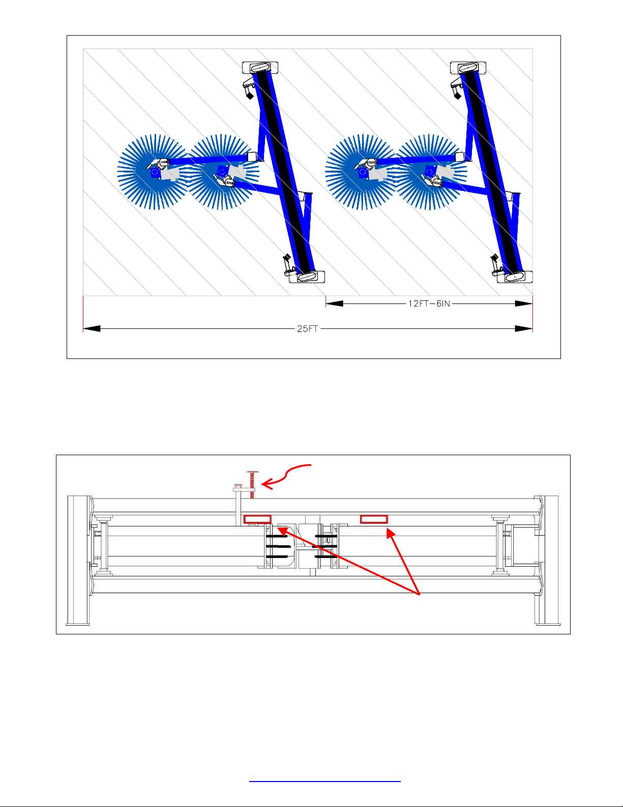
Compact Design: Utilizes only 14’-0” of Tunnel Space
Only 10’-00” Overall Height
Vehicle Clearance of More than 91”
Supplied Standard with MCWW Foam Streamers™ for Added Lubrication and Cleaning
Great Cleaning up to 180 CPH
Aluminum Structure with Color Skinz™ Snap-On UHMW Colored Covers… Great Appeal!
Electric or Hydraulic Drive Available
Choice of Cleaning Media between Cotton Cloth™, C-Channel and Star Foam
HYDRAULIC DRIVE
WRAPCHYD[ . . . . . ]03
ELECTRIC DRIVE
WRAPCELE[ . . . . . ]03
ELECTRICAL 120 VAC, 1 PH, 12 W VALVE UL® CERTIFIED
POWER: 120 VAC, 1 PH, 12 W VALVE UL® CERTIFIED
MOTORS: 3 HP (2 X 1.5 HP)
13.2-6 AMP @ 208-460 VAC, 3 PH
UL® RECOGNIZED, CSA CERTIFIED, CE MARK, IEC IP 55
HYDRAULIC 6 GPM @ 1000 PSI N/A
PNEUMATICS
2 SCFM @ 100 PSI
(INCLUDING OPTIONAL RETRACT PANEL)
2 SCFM @ 100 PSI
(INCLUDING OPTIONAL RETRACT PANEL)
WATER RECLAIMED OR FRESH:
4 GPM @ 40 PSI
RECLAIMED OR FRESH:
4 GPM @ 40 PSI

© Motor City Wash Works, Inc. 48285 Frank, Wixom Michigan 48393 U.S.A. Phone: 248.313.0272 ▪ Fax: 248. 313.0271
8MANLWRPCROVR01 09-16-20 www.motorcitywashworks.com 2
Suggested Installation Tools and Materials
Hammer Drill with 5/8” Drill bit (8) Wedge Anchor Bolts 5/8” x 6”
Sledge Hammer Set of Standard Ratchet and Sockets
Set of Standard Combo Wrenches Torpedo Level and Chalk Line
Measuring Tape Safety Goggles
Standard Screw Drivers Reusable Hydraulic Fittings
3/8” OD Polyflow Tubing 1/2" Hydraulic Hose
2000 LBS Fork Lift Truck 1000 LBS Proof L-Clamp
Notes and safety Symbols
Where necessary, important points will be highlighted in this manual, using the following symbols:
NOTE: PROVIDES FURTHER INFORMATION!
WARNING! DANGEROUS SITUATION WHICH MAY CAUSE
EQUIPMENT DAMAGE, PERSONAL INJURIES OR FATALITIES!
Always follow all notes, warnings, and instructions. Failure to do so may have serious
consequences on the overall performance of the equipment and/or the safety of the
people working on the equipment!
Installation Instructions for Cross-Over™ Wrap Around
Open all boxes and crates, and verify that you have all the required components and your installation
materials.
Locate where the wrap around will be installed and verify that the area is sufficiently large for your MCWW
CROSS-OVER™ WORKING ENVELOPE and DIMENSIONS (see Picture #1 though #5).
STOP! PRECAUTION TO AVOID EQUIPMENT
MALFUNCTION OR ERROR!

© Motor City Wash Works, Inc. 48285 Frank, Wixom Michigan 48393 U.S.A. Phone: 248.313.0272 ▪ Fax: 248. 313.0271
8MANLWRPCROVR01 09-16-20 www.motorcitywashworks.com 3
Pic #1 Cross-Over™ with Cotton Cloth™ Overall Envelope
Pic #2 Cross-Over™ with Foam Overall Envelope
14' [168"]
15'-5" [185"]
14' [168"]
15'-5" [185"]

© Motor City Wash Works, Inc. 48285 Frank, Wixom Michigan 48393 U.S.A. Phone: 248.313.0272 ▪ Fax: 248. 313.0271
8MANLWRPCROVR01 09-16-20 www.motorcitywashworks.com 4
Pic #3 Cross-Over™ with Cotton Cloth™ Overall Dimensions
Pic #4 Cross-Over™ and Accelerator™ Top Wheel Overall Envelope
14' [168"]
10' [120"]
15'-5" [185"]
19' [228"]
9’-9”
(117”)

© Motor City Wash Works, Inc. 48285 Frank, Wixom Michigan 48393 U.S.A. Phone: 248.313.0272 ▪ Fax: 248. 313.0271
8MANLWRPCROVR01 09-16-20 www.motorcitywashworks.com 5
Pic #5 Dual Cross Over™ Operating Envelope
Remove the WRAP AROUND HUB ASSEMBLIES from the boxed and the TWO LEGS from the main
pallet. Bring to your working area. Using the fork lift, insert the forks on each side of the head assembly
center beam UNDER THE TOP CROSS BEAM (as shown in Picture #6). Remove some of the top covers
and secure one of the forks with a LARGE L or C-CLAMP (see below).
Pic #6 C-Clamp Locked on Fork Lift
Bring the head to the installation area. Raise the head assembly and SECURE THE TWO LEGS TO THE
HEAD FRAME.
Position the BACK OF THE DRIVER’S SIDE LEG 45” AWAY FROM THE INSIDE EDGE OF THE
INSIDE GUIDE RAIL (See Picture #7).
LIFTING POINTS
L or C-CLAMP

© Motor City Wash Works, Inc. 48285 Frank, Wixom Michigan 48393 U.S.A. Phone: 248.313.0272 ▪ Fax: 248. 313.0271
8MANLWRPCROVR01 09-16-20 www.motorcitywashworks.com 6
Pic #7 Distance From Leg to Conveyor Guide Rail
Snap a line on the entrance side of the base plate PERPENDICULAR to the conveyor direction (as shown
in Picture #8). Position the PASSENGER’S SIDE LEG BASE PLATE 29” FROM THE LINE.
Pic #8 Snap a Line From D-S Leg Base Plate
Using FOUR 5/8”X6” WEDGE ANCHOR BOLTS secure the DRIVER’S SIDE LEG to the floor. Detach
the CLAMP FROM THE FORK. Drop the forks slightly down to allow the passenger’s side leg to sit firmly
on the floor and leave the fork lift in place as a safety precaution. LEVEL THE DRIVER’S SIDE LEG
as well as THE HEAD ASSEMBLY. Finally, LEVEL THE PASSENGER’S SIDE LEG and secure to the
floor.
29"
CAR DIRECTION
NOTE:
THE LEG GUSSET MUST BE
ORIENTED
INWARD
29”

© Motor City Wash Works, Inc. 48285 Frank, Wixom Michigan 48393 U.S.A. Phone: 248.313.0272 ▪ Fax: 248. 313.0271
8MANLWRPCROVR01 09-16-20 www.motorcitywashworks.com 7
Pic #9 Level Equipment
Remove the shipping straps from both arms. Locate the boxes containing the COLOR SKINZ™ covers
and install on each leg, arm, and frame cross beams.
Pic #9-A Color Skinz™ Pic #9-B Color Skinz™
Secure the DRIVER’S SIDE CYLINDER AND SHOCK TO THE SECONDARY ARM (as shown in picture
#10).
Remove the PASSENGER’S SIDE PRIMARY ARM POSITIVE STOP ASSEMBLY, FLIP AROUND AND
SECURE TO THE CROSS BEAM (as shown in Picture #11).
NOTE: FOR LINE SPEED BELOW 70CPH, INSTALL
THE SHOCK AND THE CLEVIS ON THE EXIT SIDE OF
THE MOUNT (SEE PICTURE #10)
SELECT THE
PROPER COLOR
SKINZ™ COVER.
SNAP ONE SIDE OF
THE LIP, SLIDE
THE COVER
AROUND THE LEG
AND FINALLY
SNAP THE
SECOND LIP PAST
THE EXTRUSION
EDGE (see Picture
#9-B)

© Motor City Wash Works, Inc. 48285 Frank, Wixom Michigan 48393 U.S.A. Phone: 248.313.0272 ▪ Fax: 248. 313.0271
8MANLWRPCROVR01 09-16-20 www.motorcitywashworks.com 8
Pic #10 D-S Cylinder and Shock Pic #11 Passenger Side Positive Stop
Star Foam Loading Instructions:
Bring the two HUB ASSEMBLIES to your working area and remove the two compression plates from the
top of the hub (see Picture #13).
Open the washing material boxes and load in ONE 10” X 48” OD-1/4” BUN followed by TWO 8” X 48”
OD-1/4” BUNS and another 10” X 48” OD-1/8” BUN onto the hub assembly (see Picture below). Next,
load TWO 10” X 54” OD-1/8” BUNS, ONE 10” X 60” OD-1/4” BUN, and finally, ONE 8” X 60” OD-1/4”
BUN. Reinstall the two compression plates and mount the hub to the main shaft.
Pic #12 Star Foam Hub Pic #13 Star Foam Hub Assembly
10” X 48”OD
-
1/4”
10” X 48”OD
-
1/8”
10” X 54”OD
-
1/8”
10” X 54”OD
-
1/8”
10” X 60”OD
-
1/4”
8” X 60”OD
-
1/4”
8” X 48”OD
-
1/4”
8” X 48”OD
-
1/4”
COMPRESSION
PLATES
MOVE SHOCK ON
MOUNT EXIT SIDE

© Motor City Wash Works, Inc. 48285 Frank, Wixom Michigan 48393 U.S.A. Phone: 248.313.0272 ▪ Fax: 248. 313.0271
8MANLWRPCROVR01 09-16-20 www.motorcitywashworks.com 9
Cotton Cloth™ Loading Instructions:
Bring the two HUB ASSEMBLIES to your working area and remove the two compression plates from the
top of the hub. Slide 4 PVC STRIPS into each channel (see Picture #14) and temporarily hold them in
place with a small piece of masking tape.
Open the washing material boxes and start loading the hub with THREE FOAM SPACERS, followed by
ONE COTTON CLOTH™ RING, and then TWO FOAM SPACERS. Continue until you’ve installed a total
of 12 CLOTH RINGS (See Picture #15 below). Finish with THREE FOAM SPACERS.
Next, load ONE 10” X 48” OD-1/8” BUN, TWO 10” X 54” OD-1/8” BUNS, ONE 10” X 60” OD-1/4” and
finally ONE 8” X 60” OD-1/4” BUN. Reinstall the two compression plates and mount the hub to the main
shaft.
Pic #14 Star Foam Hub Pic #15 Star Foam Hub Assembly Pic #16 Star Foam Hub Assembly
C Channel Foam Loading Installation:
Mount the two HUB ASSEMBLIES on each arm as shown in Picture #17 below. You may set the bottom
of the hub BETWEEN 8” to 10” OFF THE FLOOR.
To CHANGE THE HEIGHT OF THE HUBS, remove one core from the hub assembly and loosen the
CLAMPS holding the cores in place (as shown in Picture #18 and 19). Raise or lower the entire core
assembly. Re-tighten the clamps in the new position. Re-install the core piece.
10” X 48”OD
-
1/8”
12 PCS @ 44” OD
8” X 60”OD
-
1/4”
10” X 60”OD
-
1/4”
10” X 54”OD
-
1/8”
10” X 54”OD
-
1/8”
(4) FOAM SPACERS
(2) FOAM SPACERS

© Motor City Wash Works, Inc. 48285 Frank, Wixom Michigan 48393 U.S.A. Phone: 248.313.0272 ▪ Fax: 248. 313.0271
8MANLWRPCROVR01 09-16-20 www.motorcitywashworks.com 10
Pic #17 Hub Height
Open the washing material boxes and load the foam into the bottom hub as shown in Picture #20.
Pic #20 Bottom Hub Fill
STOP!
DO NOT SET THE TOP OF THE BOTTOM HUB
HIGHER THAN 36” OFF THE FLOOR.
Pic #18: Remove Core
Pic #19: Open Core
10”X18”-0”AC
3/8” SLASH
1/8” THICK
8”X18”-0”AC
3/8” SLASH
1/8” THICK
8”X18”-0”AC
3/8” SLASH
1/8” THICK

© Motor City Wash Works, Inc. 48285 Frank, Wixom Michigan 48393 U.S.A. Phone: 248.313.0272 ▪ Fax: 248. 313.0271
8MANLWRPCROVR01 09-16-20 www.motorcitywashworks.com 11
Repeat the same process for the top hubs on both wheels.
Pic #21 Top Hub Fill
3/8" SLASH
10" X 23"
1/8" THICK
10" X 25"
1/8" THICK
3/8" SLASH
10" X 27-2" AC
1/8" THICK
3/8" SLASH
1/4" THICK
3/8" SLASH
8" X 29-1"
1/4" THICK
3/8" SLASH 16 PCS
16 PCS
16 PCS
16 PCS
16 PCS
10" X 28-1" AC
Pic #22 Top Hub Fill
Pic #23 Top Hub Fill

© Motor City Wash Works, Inc. 48285 Frank, Wixom Michigan 48393 U.S.A. Phone: 248.313.0272 ▪ Fax: 248. 313.0271
8MANLWRPCROVR01 09-16-20 www.motorcitywashworks.com 12
Electrical Installation:
Your MCWW CROSS-OVER™ WRAP AROUND requires a circuit connection of 120 VAC-15 AMPS
protected with a GROUND FAULT DETECTION SYSTEM to power the air valves operating the
SECONDARY ARM CYLINDERS.
THE CROSS OVER REQUIRES A SEPARATE
15AMPS, 120VAC, 1PH
ELECTRICAL CIRCUIT.
IN ORDER TO AVOID EQUIPMENT MALFUNCTION,
DO NOT CONNECT ANY OTHER ELECTRICAL DEVICE
ON THE SAME CIRCUIT FEEDING YOUR CROSS-OVER™.
WARNING!
THE MATERIAL REQUIRED FOR CONNECTING
THE CROSS-OVER™ IS THE
CUSTOMER’S RESPONSIBILITY!
ALL WORK HAS TO COMPLY WITH
LOCAL AND NATIONAL CODES!
You may power your CROSS-OVER™ WRAP AROUND on either the driver’s side or the passenger’s
side CONNECTION BOXES (as shown in picture #24 below).
Pic #24 Electrical Box
120
VAC
(NEUTRAL)
N
8 DCALWRPPNL0003

© Motor City Wash Works, Inc. 48285 Frank, Wixom Michigan 48393 U.S.A. Phone: 248.313.0272 ▪ Fax: 248. 313.0271
8MANLWRPCROVR01 09-16-20 www.motorcitywashworks.com 13
Pic #25 Electrical Schematic
If you have purchased the ELECTRIC DRIVE CROSS-OVER™, connect each 1.5 HP MOTOR to a
separate starter unit. Each motor has to be protected with an OVERLOAD RELAY SET AT THE MOTOR
RATED FULL LOAD CURRENT FOR THE PROPER VOLTAGE.
NOTE: NEITHER OF THE MOTOR ELECTRICAL CABLES ARE
CONNECTED TO THE MOTOR LEADS WHEN
SHIPPED FROM THE MCWW FACTORY.
OPEN THE MOTOR CONNECTION BOXES AND CONNECT THEM
TO THE MOTOR LEADS, FOLLOWING THE APPROPRIATE
CONNECTION DIAGRAM BELOW OR
ON THE MOTOR PLATE (PICTURE #26) FOR PROPER VOLTAGE.
Pic #26 Motor Connection

© Motor City Wash Works, Inc. 48285 Frank, Wixom Michigan 48393 U.S.A. Phone: 248.313.0272 ▪ Fax: 248. 313.0271
8MANLWRPCROVR01 09-16-20 www.motorcitywashworks.com 14
WARNING!
EACH MOTOR HAS TO BE PROTECTED WITH AN
OVERLOAD RELAY SET AT THE MOTOR RATED
FULL LOAD CURRENT FOR THE PROPER VOLTAGE:
6.6 AMPS @ 208 VAC - 3PH
6.0 AMPS @ 230 VAC – 3PH
3.0 AMPS @ 460 VAC – 3PH
WARNING!
EACH MOTOR STARTER AUXILIARY CONTACT HAS TO BE
CONNECTED IN SERIES WITH THE OPTIONAL AIR RETRACT PANEL (SEE
PICTURE #22), OR IF YOUR CROSS-OVER™ IS NOT EQUIPPED WITH THE
RETRACT AIR PANEL, CONNECT THE OVERLOAD CONTACTS WITH THE
EMERGENCY STOP CIRCUIT (SEE PICTURE #28).
Pic #27 Starter with Air Panel

© Motor City Wash Works, Inc. 48285 Frank, Wixom Michigan 48393 U.S.A. Phone: 248.313.0272 ▪ Fax: 248. 313.0271
8MANLWRPCROVR01 09-16-20 www.motorcitywashworks.com 15
Pic #28 Starters without Air Panel
If you have purchased the ELECTRIC DRIVE CROSS-OVER™ with the MCWW OVERDRIVE®
INVERTER BOX, connect each motor to terminal #2 and terminal #3. Connect the box to a supply of
120-208 VAC/3PH/30 AMPS CIRCUIT ONLY! (See picture #29)
Connect the RUN SIGNAL INPUT (terminal #6) to one function of your car wash controller.
Connect the retract air panel to one function of your car wash controller and through TERMINALS 4, 5.
WARNING!
THE D/S AND P/S AIR VALVE INTERLOCK CONTACT
HAS TO BE CONNECTED IN SERIES WITH THE OPTIONAL AIR
RETRACT PANEL (SEE PICTURE #29).
IF YOUR CROSSOVER® WRAP IS EQUIPPED WITH A DIFFERENT VFD,
VERIFY THAT RETRACT AIR PANEL IS CONNECTED IN SERIES WITH THE
VFD’S FAULT CONTACTS. IN THE EVENT OF A FAULT FROM THE VFD,
THE WRAP HAS TO BE RETRACTED TO AVOID POSSIBLE DAMAGES TO
THE CAR OR THE EQUIPMENT.

© Motor City Wash Works, Inc. 48285 Frank, Wixom Michigan 48393 U.S.A. Phone: 248.313.0272 ▪ Fax: 248. 313.0271
8MANLWRPCROVR01 09-16-20 www.motorcitywashworks.com 16
Pic #29 Inverter Panel

© Motor City Wash Works, Inc. 48285 Frank, Wixom Michigan 48393 U.S.A. Phone: 248.313.0272 ▪ Fax: 248. 313.0271
8MANLWRPCROVR01 09-16-20 www.motorcitywashworks.com 17
Pneumatic Installation:
Your MCWW CROSS-OVER™ WRAP AROUND requires an air supply capable of 2 SCFM @ 100 PSI.
WARNING!
IT IS IMPERATIVE TO SUPPLY THE CROSS-OVER™ PNEUMATIC
SYSTEM WITH CLEAN, DRY, COMPRESSED AIR.
ANY AMOUNT OF MOISTURE, VAPORIZED OIL, OR ANY
OTHER IMPURITIES WITHIN THE MAIN AIR SUPPLY MAY
AFFECT THE PERFORMANCE OF THE EQUIPMENT
AND LEAD TO PREMATURE WEAR OR MAJOR DAMAGE
TO THE CROSS-OVER™ DELIVERY SYSTEM OR ITS COMPONENTS.
Bring a 3/8” OD polyflow tubing air line from the main compressed air supply to the MIDDLE OF THE
TOP CROSS BEAM and connect it to the existing 3/8” push-on fitting (see Picture # 30).
Pic #30 Utilities Location
5 GPM @ 40 PSI (min)
3/4" NPT FEMALE
3/8" OD PUSN-ON FITTING
2 SCFM @ 100 PSI
AIR SUPPLY
WATER SUPPLYHYDRAULIC SUPPLY
(2) 1/2" JIC FEMALE
6 GPM @ 1000 PSI (min)
1/2" OD FOR SOLUTION
3/8" OD FOR AIR
STREAMERS SUPPLY

© Motor City Wash Works, Inc. 48285 Frank, Wixom Michigan 48393 U.S.A. Phone: 248.313.0272 ▪ Fax: 248. 313.0271
8MANLWRPCROVR01 09-16-20 www.motorcitywashworks.com 18
Pic #31 Pneumatic Schematic
Optional Retract Air Panel Installation:
Bring a 3/8” OD polyflow tubing air line from the main compressed air line to the RETRACT AIR PANEL.
Pull another 3/8” OD AIR LINE from the air panel to a tee above your MCWW CROSS-OVER™ and
connect to the ROD END FITTINGS FOR BOTH SECONDARY CYLINDERS (see Picture #32 and 33
below).
Connect the air panel SOLENOID VALVE to ONE 120 VAC OUTPUT FUNCTION from the car wash
controller and through the STARTER PANEL or the INVERTER PANEL (see picture #27 AND 29).

© Motor City Wash Works, Inc. 48285 Frank, Wixom Michigan 48393 U.S.A. Phone: 248.313.0272 ▪ Fax: 248. 313.0271
8MANLWRPCROVR01 09-16-20 www.motorcitywashworks.com 19
Pic #32 Retract Air Panel
Pic #33 Secondary Cylinder
MAIN AIR INLET
3/8" BLACK AIR LINE
CONNECT 3/8” AIR LINE
TO RETRACT AIR PANEL

© Motor City Wash Works, Inc. 48285 Frank, Wixom Michigan 48393 U.S.A. Phone: 248.313.0272 ▪ Fax: 248. 313.0271
8MANLWRPCROVR01 09-16-20 www.motorcitywashworks.com 20
Optional Mirror Bump Air Panel Installation:
Bring a 3/8” OD polyflow tubing air line from the main compressed air line to the AIR PANEL. Pull one
ORANGE 3/8” OD from the PASSENGER’S SIDE REGULATOR to the PASSENGER’S SIDE PRIMARY
CYLINDER and connect to the ROD END OF THE CYLINDER (see Picture #34 below).
Pull one PURPLE 3/8” OD AIR LINE from the DRIVER’S SIDE REGULATOR to the DRIVER’S SIDE
PRIMARY CYLINDER and connect to the ROD END OF THE CYLINDER (see Picture #34 below).
Pic #34 Bump Air Panel
Connect the DRIVER’S SIDE SOLENOID VALVE to one OUTPUT FROM THE CAR WASH
CONTROLLER and program the output to TURN ON 12” BEFORE THE FRONT OF THE CAR AND
STAY ON UNTIL THE DRIVER’S SIDE WHEEL HAS PASSED BEYOND THE MIRROR AREA (OR
ABOUT 9’ LONG).
Pic #35 Bump Air Panel 12” Before Front of Car
PASSENGER
3/8" PURPLE AIR LINE
3/8" ORANGE AIR LINE
MAIN AIR INLET
SIDE
DRIVER
SIDE
PASSENGER
SIDE
DRIVER
SIDE
This manual suits for next models
1
Table of contents
Other Motor City Wash Works DC Drive manuals
Popular DC Drive manuals by other brands

PS Automation
PS Automation PSF-Q Short operating instructions

Electro-Voice
Electro-Voice ID60D-8 Specifications

ABB
ABB ACS355 series Quick installation and start-up guide

Parker
Parker Compax3H C3H1xxV4 Series installation manual

Lenze
Lenze L-force 9400 Mounting instructions

Control Techniques
Control Techniques Emerson Focus 1 user guide

MAIMAN ELECTRONICS
MAIMAN ELECTRONICS SF6100 user manual

Leroy-Somer
Leroy-Somer GEARLESS Z2 Installation and Maintenance

YASKAWA
YASKAWA GA50U Series Installation & Primary Operation

Cumark
Cumark ES Series user manual

Festo
Festo SLG Series operating instructions

Danfoss
Danfoss VLT 8000 AQUA series operating instructions