© Motor City Wash Works, Inc. 48285 Frank, Wixom Michigan 48393 U.S.A. Phone: 248.313.0272 ▪ Fax: 248. 313.0271
REVISION 2.3 10-07-20 www.motorcitywashworks.com 1
MOTOR CITY ROCKERZ INSTALLATION MANUAL
Part # ROCKRHYD[ . . . . . . . ]
ROCKRELE[ . . . . . . . ]
(ALL COLORS)
TABLE OF CONTENTS
Equipment Specifications Page: 1
Equipment Features Page: 1
Suggested Tools and Installation Materials Page: 1
Installation Instructions Page: 2
Electrical Installations Page: 7
Hydraulic Installations Page: 8
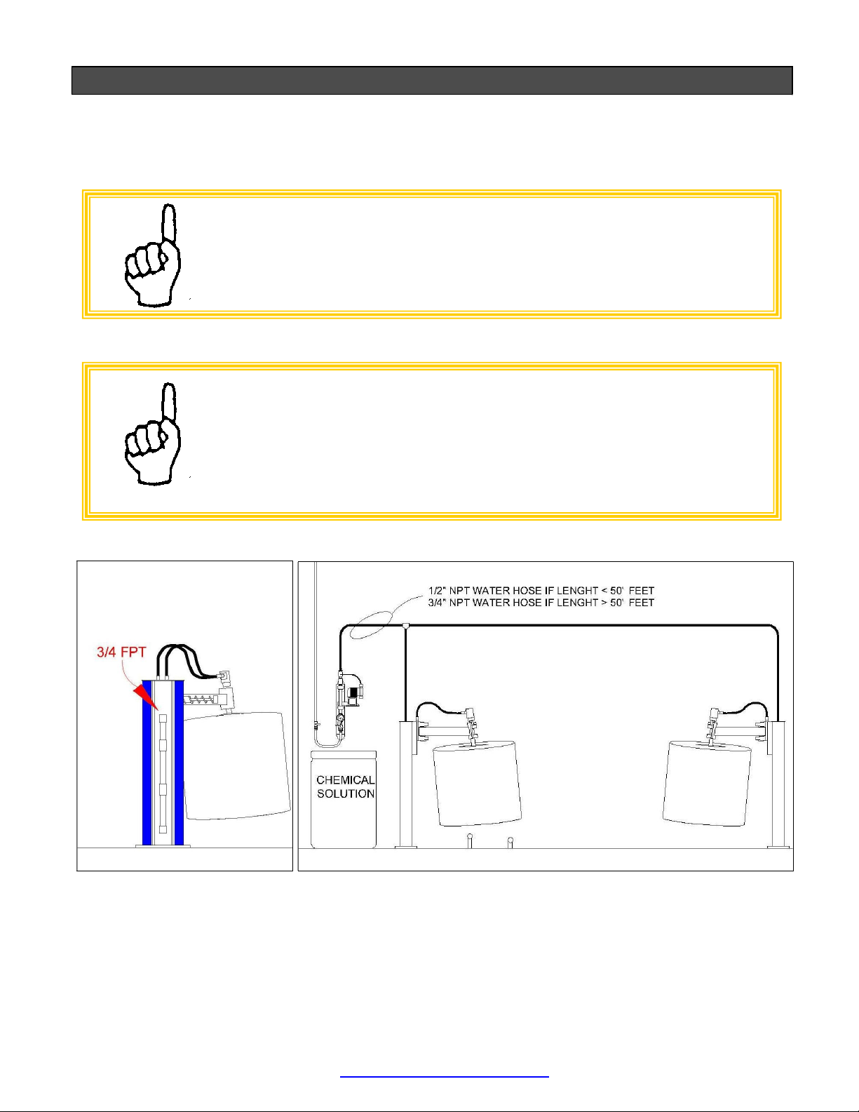
Plumbing Installations Page: 9
Start-Up Procedures Page: 10
Maintenance Page: 10
Troubleshooting………………………………………………………………………………………………………..Page: 13
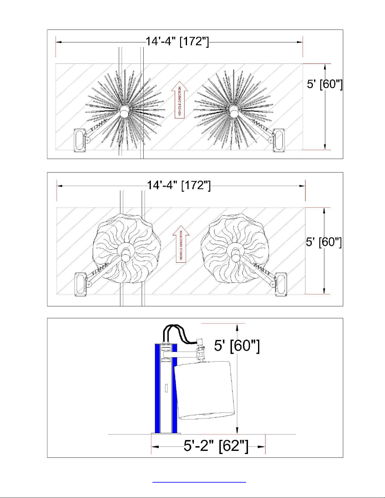
Equipment Specifications
Equipment Features
Color Skinz™ Snap On Structure Wrap
Bulk head utility connection fittings
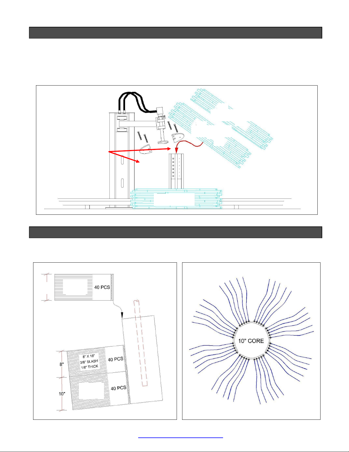
Available in either C-Channel Foam or Cotton Cloth™ wash material
Suggested Installation Tools and Materials
Hammer Drill with 5/8” Drill Bit (8) Wedge Anchor Bolts 5/8” x 6”
Sledge Hammer Safety Goggles
Set of Standard Combo Wrenches Torpedo Level
Measuring Tape Safety Goggles
HYDRAULIC DRIVE
ROCKRHYD[…….]
ELECTRIC DRIVE
ROCKRELE[…….]
ELECTRICAL N/A
MOTORS: 2 HP (2 X 1.0 HP)
9.2-4.2 AMP @ 208-460 VAC, 3 PH
UL® RECOGNIZED, CSA CERTIFIED, CE MARK, IEC IP 55
HYDRAULIC 3 GPM @ 1000 PSI N/A
PNEUMATICS
N/A N/A
WATER RECLAIMED OR FRESH:
2 GPM @ 40 PSI
RECLAIMED OR FRESH:
2 GPM @ 40 PSI