Motori Minarelli am6 User manual

1
INDICE GENERALE
PAG.
PREMESSA ....................................................... 1
NORME GENERALI Dl LAVORO ...................... 2
ISTRUZIONI PER LO SMONTAGGIO
E IL MONTAGGIO.............................................. 2
MANUTENZIONE .............................................. 14
RIMONTAGGIO MOTORE................................. 19
PREMESSA
Questo manuale fornisce le informazioni principali
per le procedure di normale intervento.
Le informazioni e le illustrazioni che compongono
questo manuale, sono aggiornate al momento della
divulgazione del manuale stesso.
MOTORI MINARELLI si riserva il diritto di apportare
modifiche in qualunque momento, senza obbligo di
preavviso.
Questa pubblicazione è indirizzata ai tecnici del set-
tore, per cui molte nozioni sono state volutamente
omesse poiché da noi giudicate superflue.
GENERAL INDEX
PAG.
FOREWORD...................................................... 1
GENERAL RULES FOR WORK ........................ 2
DISASSEMBLY AND ASSEMBLY
INSTRUCTIONS ................................................ 2
MAINTENANCE ................................................. 14
ENGINE REASSEMBLY .................................... 19
FOREWORD
This manual contains all the main information on
normal maintenance procedures.
The information and illustrations in this manual are
up to date at the moment of publishing.
MOTORI MINARELLI reserve the right to make
modifications at any time, without prior notice.
This publication is intended for specialized
technicians, so many items have been purposely
omitted as we consider them superfluous.
Edizione Aprile ’98

2
NORME GENERALI DI LAVORO
ATTENZIONE: Per qualsiasi tipo di opera-
zione è vietato l’uso di fiamma viva.
–Utilizzare esclusivamente RICAMBI ORIGINALI
MOTORI MINARELLI
– Impiegare, dove previsto, gli attrezzi speciali.
–Montare sempre guarnizioni nuove e paraolio
nuovi.
–Nel serraggio di viti e dadi, iniziare con quelli di
diametromaggiore oppurequelli interni,proceden-
do in diagonale con passaggi successivi.
–Pulire accuratamente i componenti smontati, con
benzina.
– Lubrificare le parti (ovviamente quando è possibi-
le) prima di rimontarle.
–Controllare che ogni componente sia stato mon-
tato in modo corretto.
–Senonespressamente descrittoilriassemblaggio
dei gruppi segue in senso inverso le operazioni di
smontaggio.
ISTRUZIONI PER LO SMONTAGGIO
E IL MONTAGGIO
Per eseguire le operazioni di smontaggio del motore
si consiglia di rivolgersi preferibilmente ad officine
specializzate,in ognicasoosservarescrupolosamen-
te le istruzioni riportate di seguito evitando di utiliz-
zareattrezziinadatti, che potrebberoalterarele con-
dizioni ottimali di efficienza dei componenti del mo-
tore.
Se la riparazione non potesse essere eseguita con il
motore montato sul telaio è consigliabile utilizzare
un supporto motore adeguato (kit supporto motore)
e la relativa staffa onde evitare di bloccare il motore
in una morsa con conseguenti danneggiamenti al
carter.
GENERAL RULES FOR WORK
CAUTION: For all kinds of operations it is
absolutely forbidden to use a naked flame.
–Useonly ORIGINALMOTORIMINARELLISPARE
PARTS.
– Were necessary, use the tools specially.
–Always fit new gaskets and new oil seals.
–When tightening screws and nuts, always begin
with the ones with the biggest diameter or the
insideones, proceedingdiagonallywith eachstep.
–Clean the dismantled components carefully with
petrol.
–Before putting the parts back in position, lubrifica-
te them (when possible of course).
–Checkthateach component has beenassembled
in correct way.
–Unless specified to the contrary, group are
reasembled in the inverse order in wich they were
disassembled .
DISASSEMBLY AND ASSEMBLY
INSTRUCTIONS
To perform assemblyanddisassemblyoperations on
the engine it is advisable to go to specialized
workshops, in all cases it is important to observe the
following instructions, avoiding the use of unsultable
toolswhichmay damagetheoptimum function ofthe
engine components.
Ifthe repairworkcannotbeperformedwiththe engine
on the chassis we advise the use a suitable engine
(engine support kit) support trestle thus avoiding to
clamp the engine and the relative bracket in a vice
which may cause damages to the oil sump.

3
MAINTENANCE KIT
1) Crankshaft (left) extractor
2) Tool for crankshaft (left) assembly
3) Lockingwrenchforbossclutchandhousingclutch
4) Plug for assembly of shift shaft seal
5) Plug for assembly of water pump seal
6) Plug for assembly of clutch lever seal
7) Plug for assembly of crankshaft (right)
8) Plug forassemblyof crankshaft(left) and driven
shaft.
9) Envelope for introducing driven shaft seal
10) Envelope for introducing shift shaft seal
11) Extractor for magneto flywheel
12) Wrench for shift cam
13) Wrench for clutch adjustment
14) Compass locking wrench for magneto flywheel
15) Engine support
16) AM 6 engine support bracket.
TABELLA LUBRIFICANTI
LUBRIFICANTI PER MOTO 2 TEMPI LUBRICANTS FOTTWO-STROKE ENGINES
1) Olio sintetico per miscelazione 1) Synthetic oil for separate injection
2) Olio sintetico per miscela 2) Synthetic pre-mix oil
3) Olio cambio SAE 10W30 tipo SE 3) Engine gearbox oil SAE 10W30 type SE
LUBRIFICANTI PER USO GENERICO LUBRICANTS FOR GENERAL USE
4) Grasso per cinematismi 4) Grease for moving parts
KIT DI MANUTENZIONE
1) Estrattore per imbiellaggio (lato volano)
2) Attrezzo per montaggio imbiellaggio (lato vola-
no)
3) Chiave di fermo tamburino frizione e campana
4) Tampone per montaggio anello di tenuta albero
selettore
5) Tampone per montaggio anello di tenuta pom-
pa acqua
6) Tampone per montaggio anello di tenuta leva
frizione
7) Tampone per montaggio anello di tenuta
imbiellaggio (lato frizione)
8) Tampone per montaggio anello di tenuta
imbiellaggio (lato volano) e secondario cambio
9) Busta per introduzione anello di tenuta albero
secondario cambio
10) Busta per introduzione anello di tenuta albero
selettore
11) Estrattore per volano magnete
12) Chiave per albero desmodromico
13) Chiave per registro frizione
14) Chiave a compasso di fermo volano magnete
15) Supporto motore
16) Staffa supporto motore AM 6.

4

5

6
SMONTAGGIO MOTORE
Dopo aver smontato la candela, la leva messa in
moto (solo per versione con avviamento a pedale)
ed il carburatore procedere come segue:
1) TOGLIERE l’olio dal motore rimuovendo l’appo-
sita vite di scarico.
2) SVITARE le viti di fissaggio del coperchio volano
(lato sinistro) e rimuoverlo.
Rimuovere quindi il motorino d’avviamento, (se
presente) togliendo le due viti sul carter e la vite
sulla fascetta di sostegno.
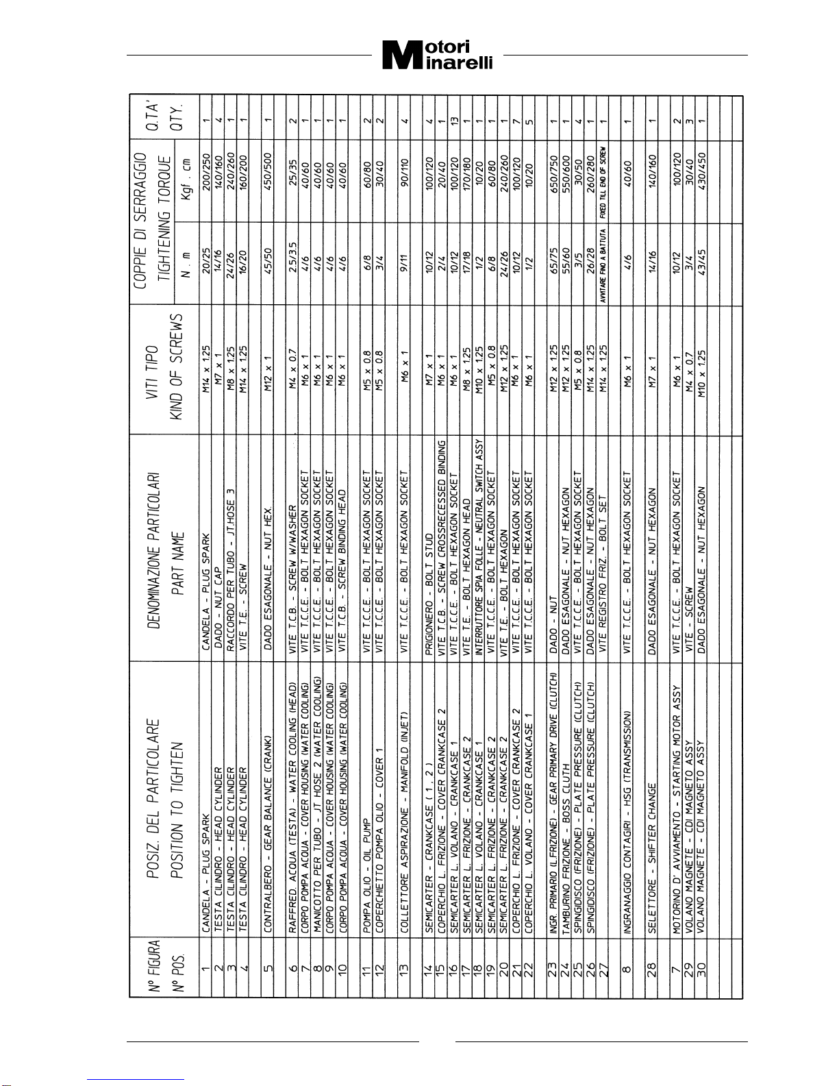
3) TOGLIERE il pignone catena rimuovendo l’anel-
lo seeger (1 - Fig. 1) usando una pinza per anelli
poi sfilare il pignone manualmente e togliere l’al-
tro anello seeger posto sotto il pignone.
4) RIMUOVERE la vite arresto scorrevole messa in
moto (Fig. 2) (solo per versione con avviamento
a pedale).
DISASSEMBLY OF THE ENGINE
After having removed the spark-plugs, starting lever
(only for kickstarter) and the carburetor proceed as
follows:
1) DRAIN the engine oil by removing the relevant
drain bolt.
2) UNSCREW cover crankcase (left) screws and
remove it.
Then remove the starting motor (if present),
removing the two screws on the crankcase and
the screw on the support strap.
3) REMOVE thesprocket driveremovingthe seeger
ring (1 - Fig. 1) using ring pliers then slip off the
sprocket drive by hand remove the other seeger
ring placed under the sprocket drive.
4) REMOVE the starting slide stop screw (Fig. 2)
(only for pedal start version).
5) TOGLIERE le viti di fissaggio del coperchietto in
plastica pompa olio.
Staccare i tubi olio dalla pompa e tapparli, quindi
sfilare il cavo comando gas dalla leva fissata alla
pompa. (Queste operazioni vanno eseguite solo
seè necessariorimuovereilmotoredal telaiodella
moto).
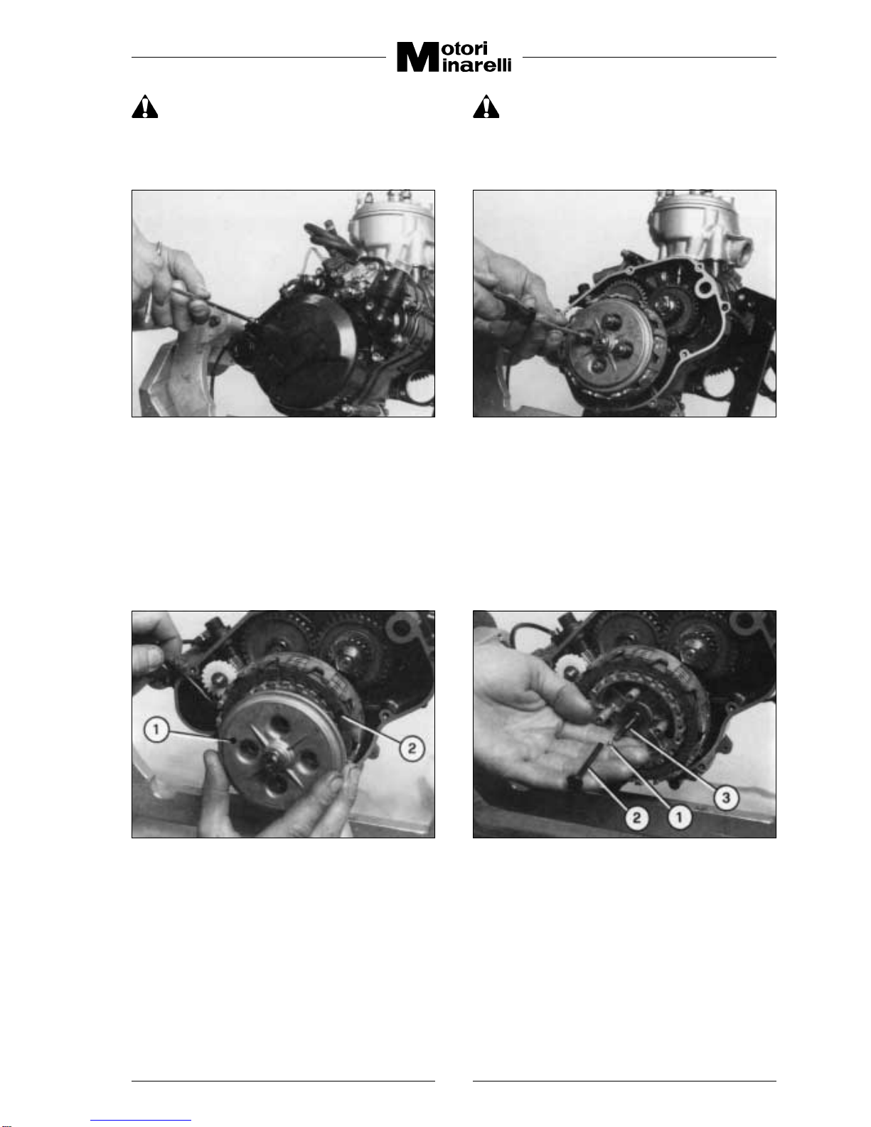
6) TOGLIERE le viti di fissaggio del coperchio fri-
zione (Fig. 3 - lato destro), quindi rimuovere il co-
perchio e relativa guarnizione.
Lo smontaggio della pompa acqua va eseguito
solose é necessariaqualche manutenzione (vedi
punto 10 nel capitolo manutenzione).
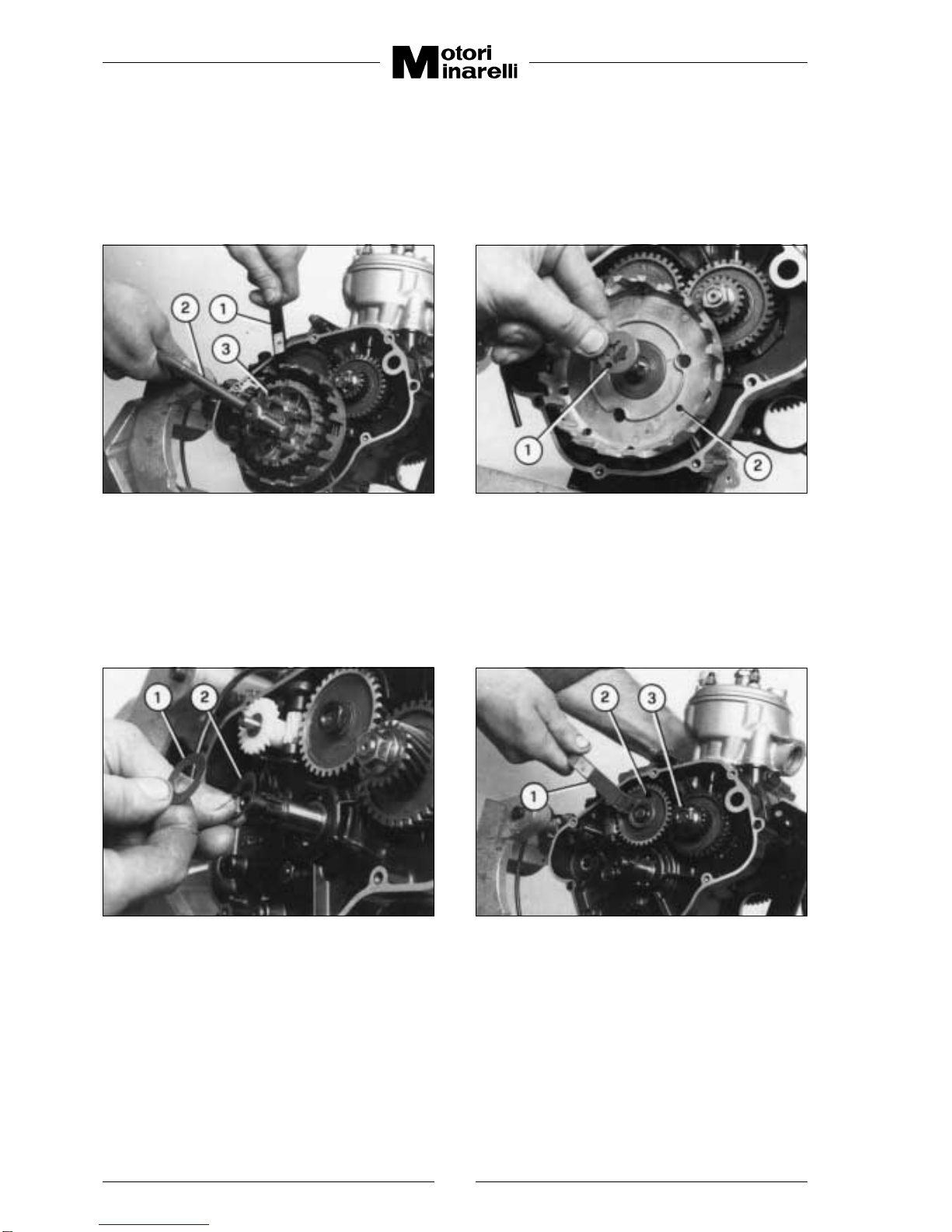
7) SFILARE dalla sua sede il gruppo messa in moto
(solo per versione con avviamento a pedale) fa-
cendo attenzione alla eventuale rondella di
rasamento che all’atto del rimontaggio dovrà es-
sere montata nella stessa posizione.
5) REMOVE the cover oil pump screws.
Disconnect the oil tubes from the pump and plug
them,thenslip the throttlecableoff the leverfixed
intothepump. (These operationsmust be carried
out only if the engine has to be removed from the
chassis of the motor-bike).
6) REMOVE the clutch cover screws (Fig. 3 - right
side), then remove the cover and its gasket.
The water pump must be disassembled only if
maintenance work is to be carried out (see point
10 in the maintenance chapter).
7) REMOVE kickstarterassy outofits housing(only
for kick starter version), being careful not to lose
the shim washer, if fitted, which must be put back
in the same position on reassembly.
Fig. 1 Fig. 2

7
ATTENZIONE: Nello smontaggio di questo
gruppo controllare bene il posizionamento
dei pezzi per rimontarlo successivamente
in modo corretto.
ATTENTION: When disassembling this
group, carefully check the position of the
pieces so as to reassemble them correctly
afterwards.
Fig. 3 Fig. 4
8) UNSCREW the screws that compress the clutch
springs (Fig. 4), then remove the pressure plate
(1-Fig. 5) and the all series of the clutch plates
(2-Fig. 5): remove the push rod the ball and the
clutch rod (1-2-3-Fig. 6) which are housed in the
central hole of the main shaft.
8) SVITARE le viti che comprimono le molle frizione
(Fig. 4), quindi sfilare il piattello frizione (1-Fig. 5)
etuttala serie dei dischi(2-Fig. 5); togliere inoltre
lo spingidisco,la sfera,I’asta frizione (1-2-3-Fig. 6)
che sono alloggiate nel foro centrale dell’albero
primario cambio.
9) STRAIGHTEN the tab of the tongued washer
under the nut that holds the clutch drum
(3-Fig.7).Then, using the special locking wrench
(1-Fig. 7) and a a 17 mm “T” wrench (2-Fig. 7),
completelyunscrewthehexagonnutofthe clutch
boss and remove it.
9) RADRIZZARE la linguetta della rondella di arre-
sto sotto il dado che fissa il tamburino frizione
(3-Fig. 7). Poi usando l’apposita chiave di fermo
(1-Fig.7)ed una chiave a “T”da17 mm (2-Fig. 7)
svitarecompletamente ildadodifissaggiodel tam-
burino frizione togliendolo.
Fig. 5 Fig. 6

8
10) SFILARE nell’ordine il tamburino frizione
(3-Fig. 7), il distanziale (1-Fig. 8) - I’ingranaggio
frizione (2-Fig. 8) - la rondella rasamento
(1-Fig. 9) - la rondella conica (2-Fig. 9) facendo
attenzione al senso in cui è posizionata per ri-
montarla successivamente in modo corretto.
Fig. 9 Fig. 10
10) REMOVE the following pieces in this order:
clutch boss (3-Fig. 7) - collar (1-Fig. 8) - driven
gear(2-Fig.8) -washer(1-Fig.9)- conicalspring
washer(2-Fig.9),payingattention tothedirection
inwhich theyare assembledso asto reassemble
them correctly afterwards.
11) USANDO l’apposita chiave di fermo volano ma-
gnete (1-Fig. 11) bloccare il volano, e con la
chiave (1-Fig. 10) allentare il dado di fissaggio
dell’ingranaggio sul contralbero.
12) RIMUOVERE l’ingranaggio sul contralbero
(2-Fig. 10) e la chiavetta.
13) SVITARE il dado (3-Fig. 10) con una chiave da
19 mm (1-Fig. 12), mantenendo sempre fermo
ilvolanocon l’appositachiave;sfilare quindi nel-
l’ordineilpignone motore, I’ingranaggiocondut-
tore contralbero, la chiavetta, la boccola distan-
ziale e l’anello or.
11) USING the magneto flywheel locking wrench
(1-Fig. 11), lock the flywheel and slacken the
retainingnutof thegearon thecountershaftwith
the wrench (1-Fig. 10).
12) REMOVE the gear on the countershaft
(2-Fig. 10) and the key.
13) UNSCREW the nut (3-Fig. 10) with 19 mm
wrench (1-Fig. 12), always holding the flywheel
still with the special wrench:then remove, in this
order, theprimarydrivegear,drivegear,thekey,
the spacer bushing and the o-ring.
Fig. 7 Fig. 8

9
14) BLOCCANDO il rotore del volano magnete con
l’apposita chiave di fermo (1-Fig. 14) svitare il
dado di fissaggio rotore con una chiave da
15 mm.
Fig.11 Fig. 12
14) BLOCKING the rotor of the magneto flywheel
with the special locking wrench (1-Fig. 14),
unscrew the rotor retaining nut with a 15 mm
wrench.
15) REMOVE the rotor of the magneto flywheel by
meansof theappropriatepuller (1-Fig.13) which
must be screwed to the threaded seating (for
the tool) on the rotor and holding it of the
appropriate wrench turn the central with a 17
mm. wrench (Fig. 13).
16) BEFORE pulling the stator make two
corrisponding reference marks, one on the
crankcase and the other on the stator plate thus
ensuring correctpositioning when reassembling
(Fig. 15).
15) RIMUOVEREil rotoredelvolano magneteusan-
do l’apposito estrattore (1-Fig. 13) che dovrà
essere avvitato nella sede filettata del rotore,
quindi tenendo fermo lo stesso con una chiave
adeguata,agiresulla vite centraleconuna chia-
ve da 17 mm (Fig. 13).
16) PRIMAdirimuovere lo statore,faredue segni di
riferimento corrispondenti, uno sulla sede nel
semicarter e l’altro sulla piastra statore per con-
sentirne l’esatto posizionamento all’atto del
rimontaggio (Fig. 15).
Fig. 13 Fig. 14

10
17) TOGLIERE levitidifissaggiodella piastrastatore
(1-Fig. 16) e rimuoverla, quindi togliere la
chiavetta (2-Fig. 16).
Fig. 15 Fig. 16
Fig. 17 Fig. 18
17) REMOVE the stator plate fastening screws
(1-Fig. 16) and remove the stator plate, then
remove the woodruff key (2-Fig.16).
18) SMONTARE la parte termica:
a) rimuovere la vite di scarico acqua posta sul
coperchio della pompa (Fig. 17) ed attende-
re che tutto il liquido refrigerante sia uscito.
(Tale operazione va eseguita solamente se
il motore non viene rimosso dal telaio della
moto; se il motore è già stato rimosso l’ope-
razione dovrebbe essere già stata eseguita
prima della rimozione).
b) svitare i 4 dadi di fissaggio testa e togliere le
relative rondelle, sfilare la testa, l’anello di
tenutatesta, ilcilindro,laguarnizionedi base
cilindro e i 4 anelli di tenuta sui prigionieri.
18) DISASSEMBLING the thermal part:
a) remove the outflow screw fitted on the
pump-cover(Fig.17)andletthecooling liquid
drain-outcompletely.(This operationmustbe
carried out only if the engine is not removed
from the chassis of the motor-bike; if the
engine has already been removed, the
operation should have been carried out
before removal).
b) unscrewthe4 cylinderheadholding nutsand
relevant washers, remove the head, o-ring
the cylinder, the gasket (cylinder) and the 4
o-ring on the studs bolt.

11
ATTENZIONE: Prima di rimuovere gli anel-
li di fermo dello spinotto chiudere con uno
straccio pulito l’imbocco del carter onde
evitare di far cadere gli anelli di fermo al-
l’interno del motore.
19) TOGLIERE quindi i 2 anelli di fermo (Fig. 18),
sfilare lo spinotto e, qualora si intenda utilizzare
uno spinotto a 2 diametri, battere leggermente
avendocuradi supportarecontemporaneamen-
te dalla parte opposta il pistone in modo da evi-
taredannialla biella.Togliereilcollettore diaspi-
razione e il pacco lamellare (Fig. 19).
20) TOGLIERE le 13 viti di unione dei due
semicarters (Fig. 20).
Fig. 19 Fig. 20
Fig. 21 Fig. 22
ATTENTION: Before removing the circlips,
seal the oil sump opening with a clean rag
thus avoiding that the removed circlips into
the engine.
19) THEN removed the 2 circlips (Fig. 18), remove
the piston pin, commonly found and if a 2
diameter pin is used, knock it gently taking care
to apply a counterpressure on the opposite side
of the piston to avoid damaging the connecting
rod. Remove the suction manifold and the reed
valve (Fig. 19).
20) REMOVE the 13 screws joining the two
crankcases (Fig. 20).
21) SEPARARE i 2 semicarters dopoaver applicato
l’appositoestrattore(1-Fig.21) al semicarterdal
lato del volano battendo con un martello di le-
gno, cuoio o plastica alternativamente sull’albe-
ro selettore e sull’albero cambio, permettendo
così il distacco graduale e parallelo dei due
semicarters (2-3-Fig. 21).
21) SEPARATE the 2 crankcases after applying the
special extractor (1-Fig. 21) on the crankcase
(left), tapping with a wooden, leather or plastic
hammer alternately on the shift shaft and on the
drive axle thus allowing gradual and parallel
removal of the two crankcases (2-3-Fig. 21).

12
22) ANNOTARSI lo spessore e la posizione di mon-
taggio di tutte le rondelle di rasamento che si
trovanoinfilatenei rispettivi alberi(Fig. 22), con-
trollando attentamente che non siano rimaste
rondelle sul carter appena tolto.
23) SFILARE l’albero del selettore e la relativa ron-
della di rasamento inferiore (Fig. 23).
Fig. 23 Fig. 24
Fig. 25 Fig. 26
22) NOTE the thickness of the shim washers which
are fitted to their relevant shafts (Fig. 22),
checking carefully that no washers are left on
the crankcase that has just been taken off.
23) REMOVE the shift shaft and its relevant lower
shim washer (Fig.23).
24) SFILAREl’albero secondario(Fig. 24)unitamen-
teall’alberodesmodromico (Fig. 25), alleforcel-
le sposta-marce (Fig. 26) e le relative rondelle
di rasamento inferiori sollevando leggermente
l’albero primario.
24) REMOVE thedrivenshaft(Fig.24)together with
the shift cam (Fig. 25), the shift forks (Fig. 26)
and then the lower washers slightly lifting the
main shaft.
25) SFILAREl’albero primario battendocon un mar-
tello di legno, cuoio o plastica facendo attenzio-
ne a non rovinare il tratto filettato.
26) TOGLIERE il contralbero equilibratore (Fig.27),
sfilare quindi l’imbiellaggio dal semicarter lato
frizione battendo con un martello di plastica o
gomma (Fig. 28) facendo attenzione a non rovi-
nare il tratto filettato.
25) REMOVE the main shaft by hammering with a
wooden, leather or plastic hammer taking care
not to damage the thread.
26) REMOVE the countershaft (Fig. 27), then take
of the crankshaft of the crankcase, tapping with
a plastic or rubber hammer (Fig. 28) and being
careful not to spoil the threaded part.

13
27) L’OPERAZIONEdi smontaggio dei cuscinettiva
eseguita solo se è necessaria la loro sostituzio-
ne, altrimenti è consigliabile non sfilarli mai dal-
la loro sede.
Fig. 27 Fig. 28
Fig. 29 Fig. 30
27) THE BEARING DlSASSEMBLY operation must
be performed only if it is necessary to replace
them, otherwise it is advisable not to remove
them from their seatings.
28) INCASE theoilpump mustbe replacedproceed
as follows (Fig. 30):
28) QUALORA si richiedesse la sostituzione della
pompa olio procedere come segue (Fig. 30):
a) Detatch the oil-feeding pipe (1) and seal it,
hus avoiding oil leaks.
b) Detatch the oil-delivery pipe from the
carburetor (2).
c) Detatch the control cable fitted to the pump
lever (3).
d) Remove the pump screws (4) and remove
the pump.
e) Fit the new pump in the seating and replace
the o-ring).
f) Insertthe deliverypipe tothe pump(2),check
that there are no air bubbles and insert it to
the carburetor.
a) Staccare il tubo di alimentazione olio pompa
(1) e tapparlo per evitare la fuoriuscita del-
l’olio stesso.
b) Staccare il tubo di mandata olio dalla pompa
al carburatore (2).
c) Staccare il cavo di comando fissato alla leva
della pompa stessa (3).
d) Rimuovere le viti di fissaggio pompa (4) e
sfilarla.
e) Rimontare la nuova pompa nella sua sede,
sostituendo l’anello di tenuta.
f) Infilare il tubo di mandata olio (2) sulla pom-
pa, verificare l’assenza di bolle d’aria e infi-
larlo sul carburatore.

14
g) Infilare il tubo di alimentazione olio (1) sulla
pompa.
h) Togliere la vite di spurgo posta sulla pompa
(5), attendere che fuoriescano olio e bolle
d’aria eventuali, fino a che uscirà solo olio; si
potrà così considerare che lo spurgo è avve-
nuto. A questo punto riavvitare la vite.
i) Rimontareil cavo comando(3) sullalevadel-
la pompa verificando che la posizione di ri-
poso della manopola gas sul manubrio corri-
sponda alla posizione di riposo della leva
stessa, altrimenti agire sul registro.
MANUTENZIONE
AVVERTENZE GENERALI
Ogni qualvolta ci si appresta a rimontare total-
mente o parzialmente il motore è sempre neces-
saria un’accurata pulizia dei pezzi, lavandoli con
benzina, soffiandoli con aria compressa e assi-
curandosi che siano ben oliati e in condizioni
perfette.
E consigliabile sostituire sempre le guarnizioni
con altre nuove in quanto le vecchie difficilmen-
te potranno evitare perdite. Si consiglia inoltre
disostituire semprei paraoliodel motorein quan-
to a seguito dello smontaggio potrebbero esser-
si rovinati e quindi aspirare aria od olio con ri-
percussioni negative sul funzionamento del mo-
tore. Utilizzare quindi gli appositi tamponi per
eseguire un corretto montaggio dei paraolio.
A Paraolio albero secondario cambio:
- Tampone montaggioparaolioalberoseconda-
rio cambio.
-Busta per introduzione paraolio albero secon-
dario cambio.
B) Paraolio imbiellaggio:
- Tampone montaggioparaolioimbiellaggio lato
frizione.
- Tampone montaggioparaolioimbiellaggio lato
volano.
C) Paraolio leva frizione:
- Tampone montaggio paraolio leva frizione.
D) Paraolio albero selettore:
- Tampone montaggioparaolioalbero selettore.
-Busta per introduzione paraolio albero
selettore.
E) Paraolio pompa acqua:
- Tampone montaggio paraolio pompa acqua.
Controllare accuratamente l’integrità dei
pezzi e predisporre tutti i vari gruppi di in-
granaggi in modo da poter eseguire cor-
rettamente il montaggio.
g) Insert the oil-feeding pipe (1) to the pump.
h) Remove the bleeder screw to be found on
the pump (5) wait until eventual air bubbles
mixed with oil drain out when only oil comes
out the bleeding is complete. Tighten the
screws.
i) Reassemblethe controlcable (3)to thepump
lever checking that when the throttle cable
that is fitted to the handlebar is in the idle
position it corrisponds to the rest position to
lever itself, otherwise adjust it by means of
the adjustment screw.
MAINTENANCE
GENERAL WARNING
Every time the engine is to be reassembled
(totally or partially) it is necessary to thoroughly
clean the parts by washing them with petrol,
drying them with compressed air and making
sure that the yare well oiled and in perfect
condition.
It is always advisable to replace the gaskets
because the old ones will cause a loss of
pressure. We suggest you always replace the
crankshaft oil seals because during disassembly
operations they may be damaged thus letting in
air or oil and hampering engine performance.
So always use the special plugs to ensure correct
assembly of the oil seal.
A) Driven shaft oil seal:
- Driven shaft oil seal assembly plug.
-Envelope for introducing gearbox driven shaft
seal.
B) Crankshaft oil seal:
- Crankshaft (right) oil seal assembly plug.
- Crankshaft (left) oil seal assembly plug.
C) Clutch lever oil seal:
-Clutch lever oil seal assembly plug.
D) Shift shaft oil seal:
-Shift shaft oil seal assembly plug.
-Envelope for introducing shift shaft oil seal
assembly plug.
E) Water pump oil seal:
- Water pump oil seal assembly plug.
Check carefully that the pieces are whole
and arrange all the various groups of gears
in such a way that assembly may be carried
out correctly.

15
PREPARAZIONI PREVENTIVE
1) LAVARE i due semicarters e i cuscinetti con ben-
zina e soffiarli con aria compressa, verificando
che la rotazione dei cuscinetti sia scorrevole e
senza rumorosità.
ATTENZIONE:Se fosse necessaria la so-
stituzione di un cuscinetto bisognerà ri-
scaldare la sede prima della installazio-
ne del nuovo cuscinetto. (Fig. 29).
2) VERIFICAREl’integrità dell’imbiellaggioe control-
lare che non vi siano imperfezioni, specie nelle
posizioni di alloggio dei cuscinetti e controllare
che il montaggio sul lato del volano avvenga con
interferenza.Controllare conuncomparatore l’ec-
centricità dei due semialberi dell’inbiellaggio. Il
valore massimo di eccentricità non deve essere
superiore a 0,04 mm. In caso contrario eseguire
la centratura. Controllare inoltre la perpen-
dicolarità della biella.
3) VERIFICARE l’integrità del cambio e montare le
rondelle di rasamento al giusto posto.
Nel caso di sostituzione assicurarsi che esso sia
montato nelle stesse condizioni di lavoro del pre-
cedentee conun giocoassiale inferiorea0,1mm.
Perottenereciò rilevareladistanza deirasamenti
sul carter e sui pezzi e compensare la differenza
conrondelle di spessoramentomontandole come
indicato (Fig. 31).
4) RILEVARE la distanza del rasamento dell’albero
desmodronicosiasul carterchesul pezzo ecom-
pensare la differenza con rondella di
spessoramento disposta come indicato (Fig. 32).
Il gioco assiale deve essere inferiore a 0,1 mm.
Fig. 31 Fig. 32
PREVENTIVE CARE
1) WASH the two crankcases and the bearings with
petrol and blow them with compressed air, check
that the bearings run freely and noiselessly.
ATTENTION: If it should be necessary to
replace a bearing, the housing must be
heated before installing the new bearing
(Fig. 29).
2) CHECK the cranckshaft integrity and check
that there are no faults particularly near the
bearing seatings and check that the fitting on
the flywheel side is perfect (no negative
allowance). Using a comparator, check the
eccentricity of the crankshaft assy. The
maximum eccentricity value must not exceed
0,04 mm.Otherwise centering must be carried
out. Check also that the con-rod is
perpendicular.
3) VERlFYtheintegrityofthe transmissionassyand
fit the shim washer to its appropriate seating.
In case of replacement make sure that the newly
fitted part is placed as the old one and that the
end float does not exceed 0.1 mm.
To obtain thedescribedresultverifythedistances
of the shim washers of the crankcase and on the
parts and if necessary compensate with shim
washers fitting them as shown in figure (Fig.31)
4) VERIFY the distance of the shim washers of the
shift-cam both on the crankcase and on the part,
if necessary compensate the difference using a
shim washer as shown (Fig. 32).
The end float must be less than 0,1 mm.
fi
fi

16
5) VERIFICAREla distanzadei rasamentidell’albero
selettore sia sul carter che sul pezzo e compen-
sare la differenza con rondelle di spessoramento
montandole come indicato (Fig. 33). Il gioco as-
siale deve essere inferiore a 0,1 mm.
6) CONTROLLARE che il gruppo frizione sia effi-
ciente. Per fare ciò verificare la buona condizio-
ne dei dischi in ferro, che le tacche di traino sui
dischi in sughero non siano eccessivamente de-
formate e che il loro rivestimento non presenti
bruciature. Controllare le scanalature del tambu-
rino frizione che non siano eccessivamente in-
taccate come pure le asole della campana frizio-
ne.Verificare anche che la lunghezza delle molle
frizione non sia inferiore al valore minimo di
mm 29,5 (Fig. 34) nel qual caso sostituirle.
Fig. 33 Fig. 34
5) VERIFY the distance of the shim washers of the
shift shaft both on the crankcase and on the part,
if necessary compensate the difference using
space washers as shown in the figure (Fig. 33).
The end float must be less than 0.1 mm.
6) CHECK that the clutch assy is efficient, to do so
verify if the clutch plate are in good conditions,
that the drawing notches on the friction plate are
not excessively deformed and that their coating
is not burnt.
Check that the grooves on the clutch boss have
not been too deeply marked; similarly check the
slots on the clutch housing.
Also check that the clutch springs are not shorter
than the allowable minimum 29,5 mm (Fig. 34), if
they are shorter replace them.
7) CAREFULLY clean the carbon crust from the
piston top by means of a common scraper taking
care not to damaged the piston itself.
Verify that it is well coupled to the lubricated
piston-pinwhich mustpresentanoptimumsurface
and that can be fitted by manual pressure but it
must not yield under its own weight.
8) CHECK that the piston rings do not have faults of
any type and that the clearance between the two
ends is within the values shown in the chart.
7) PULIRE accuratamente il cielo del pistone dalle
incrostazioni carboniose usando un comune
raschietto facendo attenzione a non danneggia-
re il pistone stesso.
Verificare che il mantello non presenti rigature o
tracce di grippatura.Verificare inoltre il buon ac-
coppiamento con lo spinotto lubrificato, il quale,
oltre all’integrità della sua superficie, deve esse-
re montabile con la semplice pressione della
mano, ma non deve cadere sotto l’azione del suo
stesso peso.
8) CONTROLLARE che i segmenti non presentino
anomalie di alcun genere e che la distanza tra le
estremitàsiacompresa nei valoriindicati nella ta-
bella seguente.
SEGMENTO DISTANZA
Nuovo 0,15 ÷0,30 mm
Usato fino a 1,0 mm
RINGS DISTANCE
New 0,15 ÷0,30 mm
Used to a 1,0 mm

17
Ilcontrollo deve esserefatto conunospessimetro
introducendo il segmento nel cilindro e facendo
attenzione a disporlo orizzontalmente (Fig. 35).
9) CONTROLLAREchela canna delcilindrosia pri-
va di tracce di grippaggio o di usura e non vi sia-
no rigature di alcun genere. Controllare con un
alesametro il diametro del cilindro in due direzio-
ni a 90°tra loro (una parallela e l’altra perpendi-
colare all’asse dello spinotto) (Fig. 36). Il limite di
ovalizzazione è di 0,03 mm., oltre il quale sostitu-
ire il cilindro.
Fig. 37
Fig. 35 Fig. 36
The checks must be carried out using a feeler
gauge making sure to position it horizontaly
(Fig. 35)
9) CHECK that the cylinder water jacket does not
haveseizing notches orincreasing-rate wearand
that there are no scorings of any kind .By means
of a bore measuring device check the cylinder
boreintwodirectionsat 90°from eachother(one
parallel to the piston pin axis the other
perpendicular to it) (Fig. 36). The maximum
ovalization allowable is 0.03 mm over wich it is
necessary to replace the cylinder.
Ripetere le misure in più punti nel tratto di canna
compreso tra il piano superiore del cilindro e la
luce di scarico (Fig. 37).
Repeat the measurements on other parts of the
cylinderwaterjacketbetweenthetop plane ofthe
cylinder and the exhaust port (Fig. 37).
Verificarequindi il diametrodel pistone econfron-
tarlo con il diametro del cilindro (Fig. 36). Then check the diameter of the piston and check
it against the diameter of the cylinder (Fig. 36).
POSIZIONARE IL FORO
DEL TERMOSTATO
COME FIGURATO

18
Il gioco massimo consentito è di 0,10 mm, oltre
tale limite si consiglia la sostituzione del pisto-
ne, vedi tabella seguente.
Fig. 38
The maximum end float is 0,10 mm, over this
limit we suggest replacing the piston.
10) POMPA ACQUA
a) Appoggiare su un piano il semicarter della
frizione (lato destro).
b) Montare il paraolio nel senso corretto come
indicato (Fig. 38).
c) Montare poi la girante, la guarnizione, i grani
e il coperchio pompa acqua.
10) WATER PUMP
a) Placethe crankcase(right)on aplanesurface
b) Fit the oil seals as shown in (Fig.38).
c) Fit the impeller shaft, the gasket, the dowels
pin and the water pump cover.
TABELLA DI ACCOPPIAMENTO
COUPLING CHART
TIPO MOTORE GIOCO MIN/MAX TOLL. PISTONE TOLL. CILINDRO SELEZIONE
ENGINE TYPE CLEARANCE MIN/MAX PISTON TOLL. CYLINDER TOLL. CHOICE
AM 50 (ACQUA) 0.049 000000 –0,063 –0,057 –0,007 –0,002 Y
cod pistone 62.0412.0 –0,056 –0,050 –0,001 +0,006 Z
(CILINDRO IN GHISA) 000000 –0,049 –0,043 +0,007 +0,012 V
(CAST IRON CYLINDER) 000000 0.062

19
RIMONTAGGIO MOTORE
1) APPOGGIARE su un piano il semicarter della fri-
zione (lato destro), quindi sistemare la molla e la
sfera segnamarce nell’apposita sede, mettendo-
vi un po’ di grasso, onde evitarne la fuoriuscita.
2) INFILARElarondella dirasamento(spessore 0,6
mm) sull’albero secondario avendo cura di met-
tere un po’ di grasso per farla rimanere aderente
all’ingranaggio della 1ª velocità, montare quindi
la forcella nello scorrevole della 1ª velocità e poi
prenderel’alberoprimario accostarlo alseconda-
rio e abbassare tutto il gruppo contemporanea-
mente (Fig. 39). Montare poi l’albero desmodro-
nico (Fig. 40) e successivamente la forcella nello
scorrevole della 2ª e 3ª velocità con il relativo
perno di guida (Fig. 41).
Fig. 41 Fig. 42
Fig. 39 Fig. 40
ENGINE REASSEMBLY
1) PLACE the crankcase (right) on a plane surface,
then fit the spring and the gear selection poppet
ball in their seatings, cover them with grease so
that they don’t slip out.
2) SLIP the shim washer (0,6 mm thick) into the
driven shaft, being careful to apply a little
grease to make it adhere to the 1st wheel gear,
then fit the fork in the 1st wheel gear; take the
main shaft, bring it next to the driven shaft and
lower the whole group at the same time (Fig.
39).
Next fit the shift cam (Fig.40) and then the fork
in the 2nd and 3rd wheelgear with the respective
guide pin (Fig. 41).

20
3) VERIFICARE il buon funzionamento del cambio
procedendo come segue: tenendo premuto l’al-
bero desmodromico e usando l’apposita chiave
(1-Fig.42), verificaremanualmente cheogniscor-
revole del cambio nella sua posizione di innesto,
sia della marcia inferiore che di quella superiore,
abbia un gioco assiale di 0,1 ÷0,2 mm. Qualora
tale condizione non fosse rispettata verificare se:
a) La variazione del gioco assiale di ogni scorre-
vole risulta costante verso le marce inferiori o
superiori in questo caso modificare lo spes-
sore della rondella sotto l’albero desmo-
dromicoecompensarelavariazione conquella
superiore per mantenere invariata la distanza
dei rasamenti.
b) La variazione del gioco assiale è diversa per
ogni scorrevole, la causa è dovuta ad un’im-
precisasquadratura dellaforcella,quindi prov-
vedere.
c) Montare le rondelle di spessoramento supe-
riori preventivamente stabilite.
4) MONTAREilgruppo selettore (Fig.43)con laron-
della inferiore (spessore di 0,6 mm) e infilare i
beccucci della molla di richiamo nel relativo pon-
te di ancoraggio e verificare che:
a) Tenendo premutoa fondosial’albero selettore
che l’albero desmodromico, i beccucci della
forcella di comando debbono sfiorare il piano
superiore della camme. In caso contrario mo-
dificarelo spessoredellarondella inferiorecon
uno più appropriato e compensare la varia-
zione con quella superiore per mantenere in-
variata la distanza dei rasamenti.
b) Posizionandol’alberodesmodromico in 2ªve-
locità,si dovrà verificarel’equidistanza dei rulli
della camme dai beccucci della forcella. In
caso contrario agire sui terminali della molla
eseguendo leggere deformazioni fino a con-
dizione ottenuta.
Fig. 43 Fig. 44
3) VERIFY that the gears function perfectly as
follows:depressing the shift cam by means of the
appropriate wrench (1-Fig. 42), manually check
thateach freesliding partof thegear inits inserted
gear position, of both the lowest and highest
gears, must have an end float of 0,1 ÷0,2 m.
If its conditions are different verify if:
a) The variation of the end float of each sliding
part is constant from the lowest to the highest
gear, in this case adjust the shim washer
beneath the shift cam and compensate the
variation with the upper shim washer thus
keeping the shim washer’s distance
unchanged.
b) The variation of the end float is different for
each sliding part, the cause is a bad framing
of the gearshift forks therefore repair.
c) Fit the previously set shim washers.
4) INSERT the shift-shaft (Fig. 43) with the lower
washers (0,6 mm thick) and insert the return
spring hooksin therelevant anchoring bridgethen
check that:
a) Depressing the shift-shaft and shift cam
together the hooks of the gearshift fork
must lightly touch the cam. If they do not,
change the shim washer with a more suitable
one and compensate the variation with the
uppershim washersoastokeeptheir distance
unchanged.
b) Setting the camshaft in second speed, verify
that the cam rollers are equidistant from the
gearshift fork hooks. If not, slightly deform the
spring ends until the required condition is
obtained.
Table of contents