manuals.online logo
Brands
  1. Home
  2. •
  3. Brands
  4. •
  5. Motorline professional
  6. •
  7. Security Sensor
  8. •
  9. Motorline professional M1601 Use and care manual

Motorline professional M1601 Use and care manual

Other Motorline professional Security Sensor manuals

Motorline professional MD150 Operation and installation manual

Motorline professional

Motorline professional MD150 Operation and installation manual

Motorline professional MR30 Use and care manual

Motorline professional

Motorline professional MR30 Use and care manual

Motorline professional MR27 Instruction Manual

Motorline professional

Motorline professional MR27 Instruction Manual

Popular Security Sensor manuals by other brands

Honeywell Home PROSiXCOCN Installation and setup guide

Honeywell Home

Honeywell Home PROSiXCOCN Installation and setup guide

Duevi SIRPZ-RB-868 Operation

Duevi

Duevi SIRPZ-RB-868 Operation

RKI 65-2483RK Operator's manual

RKI

RKI 65-2483RK Operator's manual

Nortech PD160 Enhanced Series user manual

Nortech

Nortech PD160 Enhanced Series user manual

Omron K8AC-H2 manual

Omron

Omron K8AC-H2 manual

Agilent Technologies G8610 Series Quick reference card

Agilent Technologies

Agilent Technologies G8610 Series Quick reference card

Shinko SE2EA-1-0-0 instruction manual

Shinko

Shinko SE2EA-1-0-0 instruction manual

Det-Tronics X Series instructions

Det-Tronics

Det-Tronics X Series instructions

ACR Electronics COBHAM RCL-300A Product support manual

ACR Electronics

ACR Electronics COBHAM RCL-300A Product support manual

TOOLCRAFT 1712612 operating instructions

TOOLCRAFT

TOOLCRAFT 1712612 operating instructions

Elkron IM600 Installation, programming and functions manual

Elkron

Elkron IM600 Installation, programming and functions manual

Bosch WEU PDO 6 Original instructions

Bosch

Bosch WEU PDO 6 Original instructions

THORLABS PDA10JT user guide

THORLABS

THORLABS PDA10JT user guide

Waeco UV-DETECT operating manual

Waeco

Waeco UV-DETECT operating manual

Intermatic IOS-DSIMF manual

Intermatic

Intermatic IOS-DSIMF manual

Siemens AZL66 Series manual

Siemens

Siemens AZL66 Series manual

BTI Profiline Multi Finder operating instructions

BTI

BTI Profiline Multi Finder operating instructions

Challenger SL01 instruction manual

Challenger

Challenger SL01 instruction manual

manuals.online logo
manuals.online logoBrands
  • About & Mission
  • Contact us
  • Privacy Policy
  • Terms and Conditions

Copyright 2025 Manuals.Online. All Rights Reserved.

7
6
2
8
3
5
4
1
V2.0
REV. 06/2016
EN
1LED 5JST cable input
2Detetor's cable connector (control board) 6Suport place
3Suport place 7Sensitivity Reg. Potentiometer
4JST connector 8Detector
TECHNICAL SPECIFICATIONS CHARACTERISTICS BOARD
• Technology 12~24V AC/DC (-/+10%)
• Transmission frequency Relay
• Transmission power 65mA
• Transmission Density 130mA
• Maximum installation height 3500mm
• Installation angles vertical: 0 to 90 | lateral: -30 to 30
• Detection zone (Mounting Height: 2.2m) 6m (W) x 3m (D)
• Detection type Movement
• Minimum speed 5cm/s
• Power Supply 12V to 24V AC/DC +30% /-10%
• Frequency 50 to 60Hz
• Consumption <2W (VA)
• Pause time 1.0sec
• Working temperature -25C to C
• Protection degree IP54
• Standards R&TTE 1999/5/EC; EMC89/336/EEC
• Material ABS
• Colour Black
• Dimensions 120 x 80 x 50 mm
• Weight 0.265kg
• Cable length 2500mm
RELAY OUTPUT
• Contact maximum voltage 42V AC - 60V DC
• Contact maximum current 1A (resistive)
• Maximum power 30W (DC) / 60VA (AC)
M1601 | USER'S AND INSTALLER'S MANUAL
. Fix the radar firmly in order to avoid vibrations.
. Do not cover or block the sensor's field of action.
. Avoid placing moving objects in sensor proximity.
. Avoid fluorescent lamps near the sensor.
. Avoid touching the electronic components.
. Turn the potentiometer slowly and without forcing.
• SPECIAL CARE DURING INSTALLATION
RADAR INSTALLATION
-  
01.5
1.5
3
4.5
1.5
3
4.5
3 31.5
01.5
1.5
3
4.5
3 31.5
01.54.5 3 31.5 4.5
01.5
1.5
3
4.5
1.5
3
4.5
3 31.5
01.5
1.5
3
4.5
3 31.5
01.54.5 3 31.5 4.5
0º
45º
30º
15º
Padieira
15º 30º 45º
MAXMIN
01.5
1.5
3
4.5
1.5
3
4.5
3 31.5
01.5
1.5
3
4.5
3 31.5
01.54.5 3 31.5 4.5
12-24V
AC/DC
COM
NO
EN
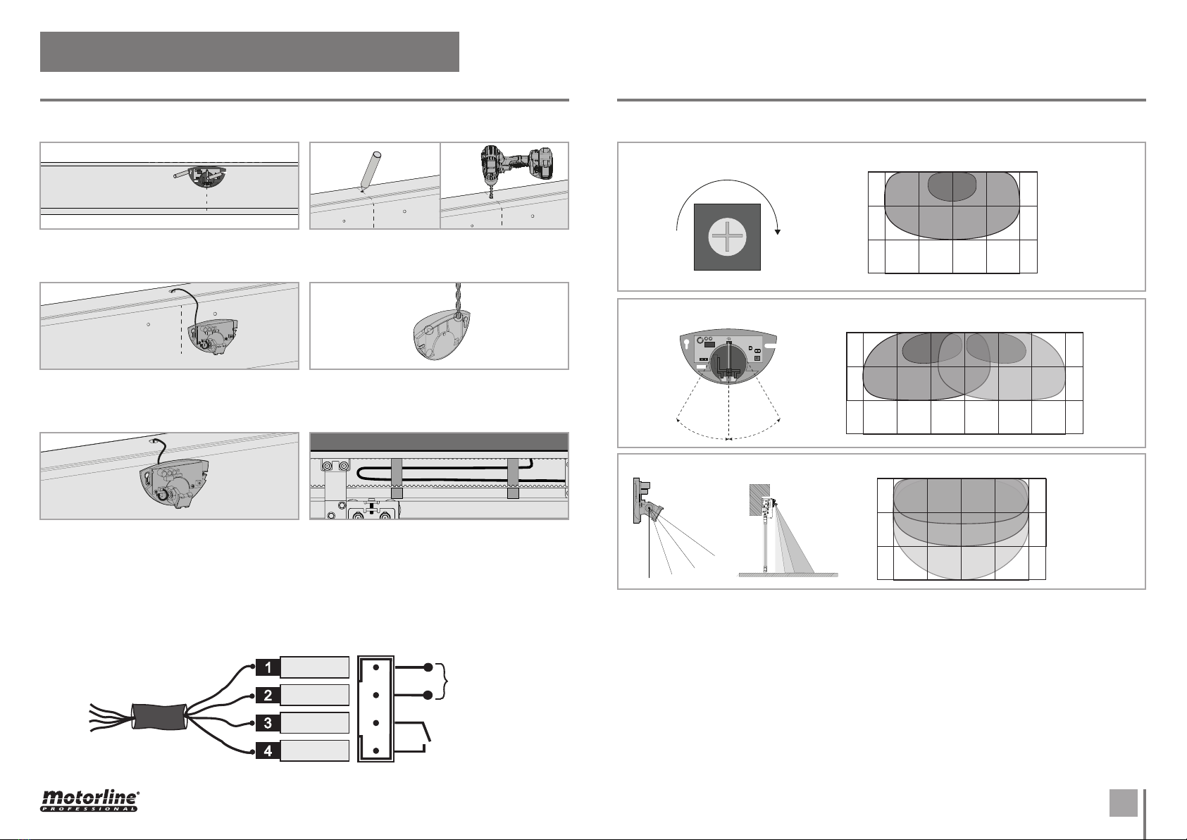
RADAR INSTALLATION ADJUSTMENTS
Alignment between
radar and safe.
. Place the radar centered with the safe's cover
and aligned by the upper limit. Mark and drill the
holes.
. Make a hole on top of the safe to pass the cable
from the inside to the outside.
. The radar has two cable outputs on the top.
With the radar closed, choose one of them and,
with the help of a drill, open the cable passage.
. Finally, stretch and fix the cable inside the safe
door, so that it does not interfere with the move-
ment of other components such as belt or carts.
. Pass the cable through the hole made, and
connect it in the existing connector inside the
radar and in the connection's board inside the safe
(connections scheme).
. Reopen the radar a fix it on the holes previously
made. Place the frontal cover. The cable should go
through the passage made on top of the radar in
the preceding paragraph ().
• INSTALLATION
• CONNECTION DIAGRAM
BROWN
YELLOW
GREEN
WHITE
Adjusting the sensitivity determines the operation area:
Adjusting the lateral angle determines the position of the operation area:
Adjust the vertical angle determines the depth of the operation area:
Vertical
angle : 
Assembly
height: .m
• SENSITIVITY AND RANGE ADJUSTMENTS
M1601 | USER'S AND INSTALLER'S MANUAL