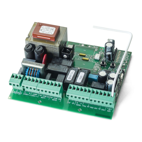
Motorline MC2 User manual

ELECTRONIC CONTROL UNIT MC2
Single-phase electronic control unit for the automation of
swinging gates with incorporated radio receiver.
TECHNICAL DATA:
- Power supply : 230 Vac 50- 0Hz 1 00W max.
- Flashing beacon output : 230 Vac 500 W max.
- Motor outputs : 230 Vac 500 W max.
- Electric lock output : 12 Vdc 15 W max.
- Photoelectric cells power supply: 24 Vac 3 W max.
- Low voltage safety features and commands : 24 Vcc
- Operating temperature : -10 ÷ 55° C
- Radio receiver : 433,92 MHz
- Op. transmitters : 12-18 Bit or Rolling Code
- Max TX stored codes : 150 (CODE or CODE PED)
- Container size : 190x140x70 mm.
- Protection degree : IP 5
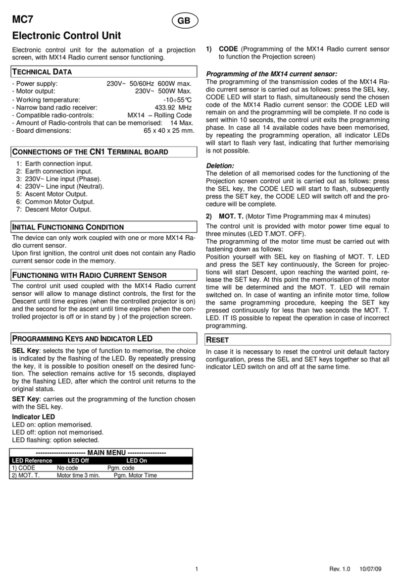
TERMINAL BOARD CONNECTIONS:
CN1:
1 : 230 Vac line input (Phase).
2 : 230 Vac line input (Neutral).
3 : 230 Vac Flashing Beacon output (Neutral).
4 : 230 Vac Flashing Beacon output (Phase).
5 : Motor 1 opening output.
: Motor 1 common output.
7 : Motor 1 closing output.
5 : Motor 2 opening output.
: Motor 2 common output.
7 : Motor 2 closing output.
CN2:
1 : Photoelectric cells control and power supply (24 Vac).
2 : Photoelectric cells control and power supply (GND).
3 : 12 Vdc 15 W (+12V) electric lock output.
4 : 12 Vdc 15 W (GND) electric lock output.
5 : PUL open-close command button input (NA).
: GND common input.
7 : PUL PED pedestrian command button input (NA).
8 : DS1 safety device input (NC).
9 : GND common input.
10 : DS2 safety device input (NC).
11 : Antenna earth input.
12 : Antenna hot pole input.
FUNCTIONAL DATA:
Automatic Operation:
Using both the radio control (CODE LED on) and the low
voltage push-button station (PUL) to control the shutter, the
following operation is obtained:
the first impulse opens the shutter until the end of the motor
time, the second impulse closes it; if an impulse arrives before
the end of the motor time, the control unit in erts motion both
during opening and closing.
Step-by-Step Operation:
Using both the radio control (CODE LED on) and the low
voltage push-button station (PUL) to control the shutter, the
following operation is obtained:
the first impulse opens the shutter until the end of the motor
time, the second impulse closes it; if an impulse arrives before
the end of the motor time, the control unit stops motion both
during opening and closing. An additional command restarts
motion in the opposite direction.
Automatic closing:
The control unit can close the shutter automatically without
sending additional commands.
The selection of this operation mode is described in the Pause
Time programming mode.
Pedestrian Passage :
The control unit can operate Motor 1 only both using the radio
control (CODE LED on) and the push-button station (PED) for
the programmed time (T. MOT. PED. LED).
Safety de ice 1 :
The control unit allows for powering and connecting
photoelectric cells according to EN 12453.
The action is not considered during opening and causes
inverted motion during closing.
The control unit must use photoelectric cells connected to
dedicated inputs; otherwise the control unit is not enabled for
operation.
Safety de ice 2 :
The control unit allows for powering and connecting
photoelectric cells according to EN 12453.
The action momentarily stops the shutter during opening; after
release, the control unit resumes opening. The action causes
inverted motion during closing.
The control unit must use photoelectric cells connected to
dedicated inputs; otherwise the control unit is not enabled for
operation.
Initial Pick-up and Motor Power Adjustment:
The electronic control unit is equipped with initial pick-up and
motor power adjustment functions that are fully managed by
the microprocessor.
The initial pick-up function is used to help the motor during
initial motion by powering the motor with maximum power for 2
seconds, also when the motor power adjustment function is
enabled.
The motor power adjustment function is used to ensure correct
motion and at the same time block the shutter in case of
obstacles without causing harm to individuals or properties.
Deceleration:
The motor deceleration function is used to avoid high-speed
closing of swinging gates at the end of opening and closing.
Deceleration can be programmed at the desired points before
total opening and closing during Motor Time programming.
Flashing Beacon Operation:
The control unit is equipped with output for 230 Vac flashing
beacon. Operation is determined by the motion of the motor
and automatic closing that, if enabled, activates the flashing
beacon also during the pause.
Operation with TIMER:
The control unit allows for connecting a timer instead of the
open-close command button (PUL).
Example: 8:00 a.m. the timer closes the contact and the control
unit commands opening, :00 p.m. the timer opens the contact
and the control unit commands closing. From 8:00 a.m. to :00
p.m. at the end of opening the control unit disables the flashing
beacon, the automatic closing and the radio controls.
PROGRAMMING :
SEL key: it selects the type of function to store, selection is
indicated by flashing LED.
By pressing the key repeatedly, you can select the desired
function. The selection remains active for 10 seconds (flashing
LED); after 10 seconds, the control unit returns to the original
status.
SET key : it programmes the information according to the type
of function selected with the SEL key. IMPORTANT: The
GB

function of the SET key can be replaced with the radio control,
if programmed previously (CODE LED on).
MAIN MENU
The control unit is supplied by the manufacturer with the
possibility of selecting some important functions.
---------------------- MAIN MENU -----------------
LED status LED off LED on
1) AUT / P-P Automatic Step-by-Step
2) CODE No code Code entered
3) CODE PED. No code Code entered
4) INB.CMD.AP Not enabled Enabled
5) T. MOT. 30 sec. motor time Programmed time
) T.MOT.PED. 10 sec. Mot. Ped. Time Programmed time
7) T. PAUSA. Without aut. closing With aut. closing
8) RIT. ANTE Without door delay. Programmed time
1) AUTOMATIC / STEP-BY-STEP:
The control unit is supplied by default with the “Automatic”
operation feature enabled (AUT/P-P LED off). To enable the
“Step-by-Step” operation feature (AUT/P-P LED on) follow this
procedure: with the SEL key go to AUT/P-P LED when flashing
and press the SET key: the AUT/P-P LED turns on. Repeat the
operation to restore the previous configuration.
2) CODE : (Radio control code)
The control unit allows for storing 150 radio controls with
different code of fixed or rolling type.
Programming.
To programme the transmission code follow this procedure:
with the SEL key go to CODE LED when flashing, send the
desired code with the radio control; programming is completed
when the CODE LED remains on permanently. If you have
stored 150 codes and you repeat the programming operation,
all programming LED’s start flashing to indicate that no codes
can be stored.
Deleting the codes.
To delete all transmission codes stored in the memory, do as
follows: press the SEL key, the CODE LED starts flashing, then
press the SET key, the LED CODE turns off and the procedure
is completed.
3) CODE PED:(Code of Pedestrian / Left Door radio control).
The programming and deleting procedure is the same as the
one illustrated above, with reference to the CODE PED. LED.
4) INB. CMD. AP: (command inhibition during opening and
pause time, if entered)
The command inhibition function during opening and pause
time, if entered, is used when automation includes the loop
detector. During opening or pause the control unit does not
detect the commands given by the loop detector at every
passage.
The control unit is supplied by default with the command
inhibition function during opening and pause time not enabled.
To enable the function follow this procedure: with the SEL key
go to INB.CMD.AP LED when flashing, then press the SET key:
the INB.CMD.AP turns on. Repeat the operation to restore the
previous configuration.
5) MOTOR TIME and DECELERATION: (Programming motor
operation time of max. 4 minutes)
The control unit is supplied by the manufacturer with predefined
motor operation time of 30 seconds without deceleration.
To modify the motor operation time, follow this procedure with
the shutter closed: with the SEL key go to T.MOT. LED when
flashing, then press the SET key rapidly, Motor 1 starts the
opening cycle; when the initial point of deceleration is reached
press the SET key again, the motor decelerates until the
desired position is reached, press the SET key to complete the
opening cycle. The T.MOT. LED starts flashing rapidly, now
repeat the programming operation for Motor 2 motor operation
time and deceleration. When the motor operation time is
programmed for opening, the T.MOT. LED starts flashing
rapidly, now repeat the programming operation for closing. To
deactivate the deceleration function, during programming, once
the opening and closing cycle is completed, press the SET key
twice in a sequence.
During programming the radio control key of the control unit
can be used instead of the ET key, if stored previously.
6) T. MOT. PED: (Programming pedestrian operation time of max. 4
minutes)
The control unit is supplied by the manufacturer with predefined
operation time of Motor 1 (Pedestrian) of 10 seconds without
deceleration.
To modify the pedestrian operation time, follow this procedure
with the shutter closed: with the SEL key go to T.MOT.PED.
LED when flashing, then press the SET key rapidly, Motor 1
starts the opening cycle; when the initial point of deceleration is
reached press the SET key again, the motor decelerates until
the desired position is reached, press the SET key to complete
the opening cycle. The T.MOT.PED LED starts flashing rapidly,
now repeat the programming operation for closing. To
deactivate the deceleration function, during programming, once
the opening and closing cycle is completed, press the SET key
twice in a sequence.
During programming the radio control key of the control unit
can be used instead of the ET key, if stored previously.
7) T. PAUSA: (Programming of aut. closing time of max. 4 min.)
The control unit is supplied by the manufacturer without
automatic closing. To enable the automatic closing function
follow this procedure: with the SEL key go to T.PAUSA when
flashing, then press the SET key, wait for the desired interval of
time, then press the SET key again; the automatic closing time
is stored and the T.PAUSA LED is on. To restore the initial
configuration (without automatic closing) go to the T.PAUSA
LED when flashing then press the SET key twice within 2
seconds; the LED goes off and the operation is completed.
During programming the radio control key of the control unit
can be used instead of the ET key, if stored previously.
8) T. RIT. ANTE : (Programming door delay of max. 15 sec.)
The control unit is supplied by the manufacturer without door
delay during opening and closing. To programme the door
delay time, follow this procedure with the shutter closed: with
the SEL key to the RIT.ANTE LED when flashing, press the
SET key, wait for the desired interval of time, then press the
SET key again; the fixed door delay time of 2 seconds during
opening is stored, the door delay time during closing is stored
for the programmed time and the RIT.ANTE LED is on.
To restore the initial configuration (without door delay) go to the
RIT.ANTE LED when flashing then press the SET key twice
within 2 seconds; the LED goes off and the operation is
completed.
EXTENDED MENU
The control unit is supplied by the manufacturer with the
possibility of selecting only the functions of the main menu.
To enable the functions of the extended menu follow this
procedure: hold the SET key pressed for 5 seconds; the
T.PAUSA and RIT.ANTE LED’s start flashing alternatively; the
user has 30 seconds time to select the functions of the
extended menu with the SEL and SET keys, after 30 seconds
the control unit returns to the main menu.
---------------------- EXTENDED MENU -----------------
LED status LED off LED on
A) AUT / P-P remote PGM = OFF remote PGM = ON
B) CODE Photoelectric cells test = ON Photoelectric cells test =
OFF
C) CODE PED. Pressure Maint. = OFF Pressure
Maint. = ON
D) INB.CMD.AP The aries effect = OFF The aries effect = ON
E) T. MOT. Closure Strike = OFF Closure Strike = ON
F) T.MOT.PED. Safety device 2 Stop input

G) T. PAUSA Flashing beacon ON/OFF
H) RIT. ANTE Flashing beacon ON/OFF
A) AUT / P-P (Remote programming of radio control) :
The control unit allows for programming the transmission code
from remote, without using the SEL key.
To programme the transmission code from remote follow this
procedure: send the radio control code continuously for more
than 10 seconds, the control unit enters the programming
mode as illustrated above for the CODE LED in the main menu.
The control unit is supplied by the manufacturer with the
remote programming of the transmission code not enabled; to
enable the function follow this procedure: check that the
extended menu is enabled (T. PAUSA and RIT. ANTE LED’s
flashing alternatively), with the SEL key go to AUT/P-P LED
when flashing and press the SET key: the AUT/P-P LED turns
on and programming is completed. Repeat the operation to
restore the previous configuration.
B) CODE (Photoelectric Cells Test):
The control unit is supplied by the manufacturer with the
photoelectric cells test enabled (in compliance with EN 12453);
to disable the function follow this procedure: check that the
extended menu is enabled (T. PAUSA and RIT. ANTE LED’s
flashing alternatively), with the SEL key go to CODE LED when
flashing and press the SET key: the CODE LED turns on and
programming is completed. The photoelectric cells test is not
performed; also if they are not connected (DS1 and DS2 inputs
must be bridged) the control unit is enabled for operation.
Repeat the operation to restore the previous configuration.
C) CODE PED: (Maintenance of Hydraulic Motor Pressure):
The control unit is supplied by the manufacturer with the
maintenance of hydraulic motor pressure not enabled. To
enable the function follow this procedure: check that the
extended menu is enabled (T. PAUSA and RIT. ANTE LED’s
flashing alternatively), with the SEL key go to CODE PED LED
when flashing and press the SET key: the CODE PED LED
turns on and programming is completed. In this way the control
unit will send a closing command to the motor every 2 hours for
2 seconds. Repeat the operation to restore the previous
configuration.
D) INB. CMD. AP (The aries (ramming) effect ) :
The control unit is supplied by the manufacturer with the aries
(ramming) effect function not enabled. To enable the function
follow this procedure: check that the extended menu is enabled
(T. PAUSA and RIT. ANTE LED’s flashing alternatively), with
the SEL key go to INB. CMD. AP. LED when flashing and press
the SET key: the INB. CMD. AP. LED turns on and
programming is completed. In this way the lock can be
unlocked and the opening operation can be performed
correctly. Before starting opening the control unit will send a
closing command for 2 seconds.
Repeat the operation to restore the previous configuration.
E) T. MOT. (Closure Strike) :
The control unit is supplied by the manufacturer with the
closure strike function not enabled. To enable the function
follow this procedure: check that the extended menu is enabled
(T. PAUSA and RIT. ANTE LED’s flashing alternatively), with
the SEL key go to T. MOT. LED when flashing and press the
SET key: the T. MOT. LED turns on and programming is
complete. If Deceleration during closing is programmed, the
control unit will add 1-sec time at maximum power (after
completing the decelerated closing operation) in order to
overcome the lock, if present. Repeat the operation to restore
the previous configuration.
F) T. MOT. PED. ( Safety de ice 2 / Stop input ):
The control unit is supplied by the manufacturer with the safety
Stop input function disabled. To enable the function follow this
procedure: check that the extended menu is enabled (T.
PAUSA and RIT. ANTE LED’s flashing alternatively), with the
SEL key go to T. MOT. PED. LED when flashing and press the
SET key: the T. MOT. PED. LED turns on and programming is
complete. In this way, the control unit changes the operation of
Safety Device 2 ( CN2 no. 9-10 ) to the safety Stop input
operation, as following: acting on any stage of the operation
stops motion immediately. An additional motion command will
be valid as long as the Stop input is deactivated, and in any
case it will close the gate with 5-second pre-flashing.
RESET :
To reset the default configuration, press the SEL and SET keys
simultaneously, all RED LED’s will turn on and then off.
DIAGNOSTICS:
Photoelectric Cells Test:
The control unit is set for the connection of safety devices
compliant with 5.1.1. section of EN 12453. The operation test
of connected photoelectric cells is performed at each
manoeuvring cycle. In case of no connection and/or no
operation, the control unit will not enable motion and will
visually indicate the test failure with simultaneous flashing of all
LED’s. Once the correct operation of the photoelectric cells has
been restored, the control unit is ready for operation. This
guarantees monitoring against failures in compliance with
Category 2 of EN 954-1.
Commands input test:
The control unit is provided with a LED for each low voltage
command input to monitor the status immediately.
Operation principle: LED on = input closed, LED off = input
open.
FOR THE USER - IMPORTANT
- The device should not be used by children or by individuals
with reduced physical or psychological abilities unless
supervision is provided or instruction given on how to operate
it.
- Do not let children play with the device; keep radio controls
out of their reach.
- CAUTION: Keep this instruction manual in a safe place and
adhere to the important safety instructions contained within it.
Non-adherence to these instructions may lead to property
damage and serious accidents.
- Examine the system frequently to check for any signs of
damage. Do not use the device if it needs to be repaired.
Warning
All operations which require the casing to be opened (such as
wire connection, programming, etc.) must be carried out during
installation, by skilled staff only.
For any other procedure which requires the casing to be
opened again (programming, repairs or site modifications),
please contact the technical assistance service.

FOR THE INSTALLER - IMPORTANT
−Before the gate automation, it is necessary to check the
good condition of the gate and its compliance with EN
12604 with respect to directive on machines.
−The control unit is not equipped with 230 Vac electric
line sectioning device. The installer is responsible for
installing a sectioning device in the system. The
sectioning device must be protected against accidental
closing in compliance with 5.2.9 section of EN 12453.
−Wiring of external electrical components must comply
with EN 60204-1 as amended in section 5.2.7 of EN
12453. The fixing of power supply leads and connection
cables must be secured through the use of cable
clamps supplied on demand.
−When drilling holes in the outer casing for the power
supply and connection wiring, and when fitting the
cable clamps, make sure everything is installed so as to
maintain the IP protection degree features as fully as
possible.
Please also make sure that the cables are fixed in
place securely.
− The rear casing is designed for wall installation (it is
designed to have holes so that it may be installed using
rawl plugs, or so that it can be fixed in place using
screws). Plan and apply all the details necessary for the
IP degree to remain unaltered after installation.
−If present, the push-button station for manual control
must be mounted in such a way that the user is not in a
dangerous position.
−The motor reducer used to move the gate must comply
with section 5.2.7. of EN 12453.
−The D. . Power upply output must be dedicated to
photoelectric cells power supply. It must not be used for
other applications.
−The control unit tests the operation of photoelectric cells
at every manoeuvring cycle to guarantee protection
against failures of anti-crushing devices of Category 2
in compliance with section 5.1.1.6 of EN 12453.
Therefore, if the safety devices are not connected and/
or operated, the control unit is not enabled for
operation.
−For the correct operation of the radio receiver, if two or
more control units are used, we recommend you to
install the devices at least 3 metres away from each
other.
Stateurop hereby declares that the product below:
Electronic Control Unit:
MC2
comply with the requirements of Directives R&TTE
99/5/EC, EMC 2004/108/EC, LVD 2006/95/EC.
Rel. 1.4 of 29-01-08
Other manuals for MC2
2
Table of contents
Other Motorline Control Unit manuals

Motorline
Motorline MC2 Use and care manual

Motorline
Motorline MC1 User manual

Motorline
Motorline MC15SC Instruction Manual

Motorline
Motorline MC10-11 Use and care manual

Motorline
Motorline MC2 User manual

Motorline
Motorline MC75 Use and care manual

Motorline
Motorline MC6 User manual

Motorline
Motorline MC7 User manual

Motorline
Motorline MC11 Use and care manual
Popular Control Unit manuals by other brands

Eaton
Eaton Series NRX installation instructions

EOS
EOS EmoTouch 3 Installation and operation manual

Dynacord
Dynacord EB DPC manual

Agilent Technologies
Agilent Technologies 81650A user guide

UNIPUMP
UNIPUMP TURBI-M3 DUAL-THRESHOLD Installation and operation manual

Siemens
Siemens SINORIX CPY-35 installation instructions