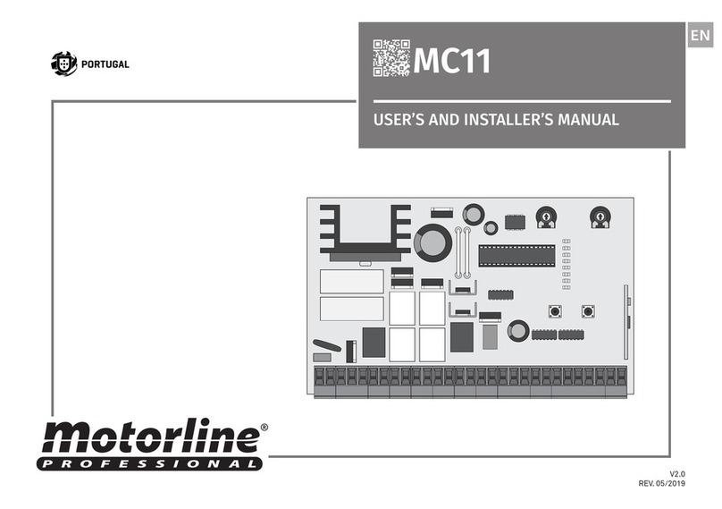
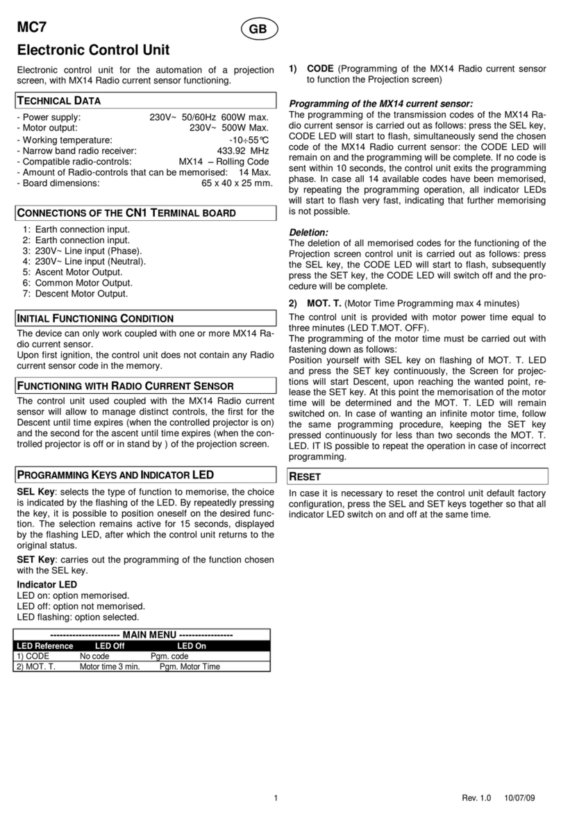
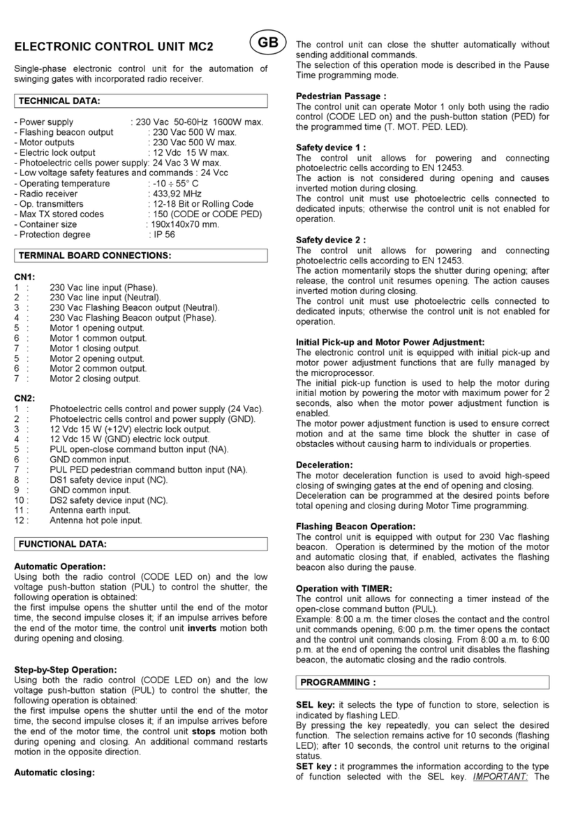
Motorline MC2 Use and care manual

v1.0
REV. 04/2015
MC2
EN
USER / INSTALLER MANUAL
MC2

1A 1B
PTPT
INDEX STANDARDS TO FOLLOW
00. CONTENT 01. SAFETY INSTRUCTIONS
1B
11
11
12
2A
3A
9B
10A
4A
10A
10B
6B
8A
ATTENTION:
• To ensure the safety of people, it is important that you read all the following instruc-
tions.
• Incorrect installation or incorrect use of the product can cause physical injury and
material damage.
• This product was designed and produced strictly for the use indicated in this manual.
Any other use, not expressly indicated here, could compromise the good condition/ope-
ration of the product and/or be a source of danger, and will void the warranty.
• ELECTROCELOS S.A. is not responsible for the improper use of the product, or other
use than that for which it was designed.
• ELECTROCELOS S.A. is not responsible if safety standards were not taken into ac-
count when installing the equipment, or for any deformation that may occur to it.
• ELECTROCELOS S.A. is not responsible for the safety and proper operation when
using components not sold by them.
• Do not make any modifications to the operator components and / or their accessories.
• Before installation unplug the automatism from the source of power.
• The installer must inform the client how to handle the product in case of emergency
and provide this manual to user.
• Keep remote controls away from children, to prevent the automated
system from being activated involuntarily.
• The customer shall not, under any circumstances, attempt to repair or tune the auto-
matism. Must call qualifid technician only.
• Connect the automatism to a 230V plug with ground wire.
• Control board for indoor use.
STANDARDS TO FOLLOW
TECHNICAL SPECIFICATIONS
PROGRAMMING PRE-RECOMENDATIONS
MAIN MENU
EXTENDED MENU 3
PHOTOCELLS TESTING AND REMOTE CONTROLS
INSTRUCTIONS FOR FINAL CONSUMERS
EXTENDED MENU 1
RESET OF CONTROL BOARD
CAPACITATOR SCHEME
INSTRUCTIONS FOR SPECIALIZED INSTALLERS
EXTENDED MENU 2
01. SAFETY INSTRUCTIONS
02. THE CONTROL BOARD
03. CONFIGURATION
04. COMPONENT TEST
05. TROUBLESHOOTING
CONTROL BOARD CONNECTION COMPONENT
06. CONNECTION SCHEME

2A 2B
PTPT
02. THE CONTROL BOARD 02. THE CONTROL BOARD
TECHNICAL SPECIFICATIONS TECHNICAL SPECIFICATIONS
The MC2 is a central electronic single phase with incorporated radio, for automation of
swing gates.
• Power supply 230V AC 50-60Hz
• Lightbulb’s output 230V AC 500W máx.
• Motor’s output 230V AC 50/60 Hz 500W máx.
• Auxiliary accessories output 24VAC 15W máx.
• Safety and remote controls in BT 24V CC
• Working temperature -10˚C to +55˚C
• Protection IP56
• Incorporated Radio Receiver 433,92 Mhz
• OP Transmitters 12-18 bits or Rolling Code
• Maximum memory capacity 150 (CODE or CODE PED)
• CONNECTOR’S DESCRIPTION
• DIMENSIONS THE BOX AND CONTROL BOARD
01 • Earth connection
02 • Earth connection
03 • Earth connection
01 • AC 230V Line Input (PHASE)
02 • AC 230V Line Input (NEUTRAL)
03 • Lightbulb / Courtesy light’s output (not blink) AC230V (NEUTRAL)
04 • Lightbulb / Courtesy light’s output (not blink) AC230V (PHASE)
05 • Motor’s Output 1 opening
06 • Motor’s Output 1 common
07 • Motor’s Output 1 closing
08 • Motor’s Output 2 opening
09 • Motor’s Output 2 common
10 • Motor’s Output 2 closing
01 • Output for power photocells 24V AC
02 • Output for power photocells (earth)
03 • Output for electric lock 12V DC 15W (+12V)
04 • Output for electric lock 12V DC 15W (earth)
05 • Input PUL button the order opening / closing (NA)
06 • Input earth common
07 • Input PUL PED button the order pedestrian (NA)
08 • Input DS1 safety device 1 (NC)
09 • Input common GND
10 • Input DS2 safety device 2 (NC)
11 • Antenna mass input
12 •Antena hot pole input
CN2CN3 CN1
205mm 115mm
140mm
252mm
125mm

3A 3B
PTPT
02. THE CONTROL BOARD 02. THE CONTROL BOARD
PROGRAMMING PRE-RECOMENDATIONS PROGRAMMING PRE-RECOMENDATIONS
• POWER AND SPEED OF MOTORS
The control board has a trimmer VR1 for adjusting the force and speed
of the motors controlled by the microprocessor. The adjustment can be
effected between 50% and 100% the power.
At each start-up movement, the control board applies the maximum
power during 2 seconds, even when it is made regulating force to a value
than not the maximum. FORZA
When you adjust the trimmer VR1 has to remake course programming, as they
could varied the times of maneuvering and deceleration.
+
-
• PROGRAMMING THE CONTROL BOARD - BUTTONS SEL/SET
SEL button: It makes the selection of the function to change. The se-
lection is identified by the flashing of the LED corresponding to the
selected function at that time.
Pressing the SEL button repeatedly will cycle through the various
functions to be programmed. The selection remains active for 10 se-
conds, after these time the control board returns to original status
(no active selection).
SET button: Makes programming the selected function through the
SEL button.
The SET button may be substituted by a remote control from the latter is pro-
grammed.
SETSEL
• OPERATION OF FLASH LAMP
The operation of the output is conditioned by the mo-
vement of the motor and automatic closing. When the
automatic closing is activated, the 230V output is ac-
tivated even during pause time.
3 4
• OPERATION WITH TIMER
Instead of a push button opening / closing (PUL), the
control board can be operated with a TIMER. With a
TIMER connected to the control board it is possible
to program an exact time for that the motor perform
both the opening and closing, in the automatic mode. 5 6
CN3
CN2
Flash lamp:
03 and 04 •This output allows connection of a flash lamp (see page 4B).
Capacitor:
05 and 07 •You must connect the capacitor between the outputs 05 and 07.
08 and 10 • You must connect the capacitor between the outputs 08 and 10.
Electric lock:
03 and 04 • This output allows connection of an electric lock (see pág.9A)
Push button / selector:
05 • Allows connection the push-button / selector to full opening (NA).
06 • Allows connection the push-button / selector to full opening (NA).
Safety circuits:
08 •This circuit allows the connection of all types of safety devices such as
photocells, safety edge, etc.
This device operates only in the gate closing and, when activated change the
direction of the automation.
10 • This circuit allows the connection of all types of safety devices such as
photocells, safety edge, etc.
This device operates in the opening and closing. In closing, change the direction
of the automation. In the opening for the movement and when was released
continues with the opening.
CN2CN3
CN1
123 12345678912345678910 11 12
CN2 CN3
Before proceeding to the control board configuration, note the following points listed
in the table below:
10

4A 4B
PTPT
03. CONFIGURATION 03. CONFIGURATION
The control board allows starting only one motor for the possible passage of peoples.
With this function, pressing the remote control, only the leave of motor 1 will open.
Programming the remote controls to pedestrian mode (LED CODE PED ON) / the remote
controls (LED CODE OFF):
01. Press the SEL button once until the LED CODE PED starts flashing.
02. Press the remote control button that you want to program during 1 second.
If you want delete remote controls, press the SET button for 1 second.
03. LED CODE PED ON indicates that the remote controls is programmed and deleted
LED indicates that the remote controls have been deleted.
• CODE PED | PEDESTRIAN OPERATION
MAIN MENU MAIN MENU
Mode automatic operates (LED AUT / P-P off):
• The first impulse the remote control / puss button activates the opening until the end
of the motor time.
• The second impulse the remote control / puss button activates the closing until the end
of the motor time.
If give an impulse before the end of the motor time,the control board will perform a inver-
sion of movement in opening and closing.
Mode of operation step by step (LED AUT / P-P on):
• The first impulse the remote control / puss button activates the opening until the end
of the motor time.
• The second impulse the remote control / puss button activates the closing until the end
of the motor time.
If give one order before the end of the motor time, the control board will stop the move-
ment in opening and closing.A new order will return the operation,performed in the other
direction to what it was before the stop.
The control unit is supplied by the manufacturer with the activated Automatic mode (LED
AUT / P-P off).
Note: If the T. PAUSE is active (on) and stop the gate during the opening, this will keep
stopped until the end of the pause time, and then make the closing. If you stop during
• AUT/P-P | AUTOMATIC OPERATION / STEP BY STEP
The control board accepts only Dip-Switch remote controls or Rolling Code MOTORLINE,
and has a maximum capacity of 150 remote controls. When trying to program the 151
remote controls, all the programming LEDs will flash simultaneously to indicate that the
memory is full.
To program new remote controls:
01. Press the SEL button as many times as necessary until the LED CODE flashes.
02. Press once the button remote control you want to program for 1 second.
03. The CODE LED lights up permanently, indicating successful programming.
To delete all configured remote controls:
01. Press the SEL button once, and the CODE LED will begin to flash.
02. Press the SET button once! The CODE LED turns off and all remote controls have been
deleted.
If the CODE LED starts fast flashing, means that the control board did not accept the
remote controls programming, because of the following reasons:
• The remote control is already programmed;
• The control board accepts only remote controls with rolling code.
• CODE | PROGRAMMING OF REMOTE CONTROLS
closing, it will stop and will restart only when receive new order.
Select operating mode:
01. Press the SEL button once, and the LED AUT / P-P will start flashing.
02. Press the SET button for 1 second.
03. The LED AUT/PP lit signals that are selecting the mode of operation step by step and
the LED off signals that is selected the automatic mode.
MAIN MENU
LED LED OFF LED aceso
• AUT/P-P LED OFF Step by step
• CODE Automatic Inserted code
• CODE PED. No code Inserted code
• INB. CMD. AP No code Activated
• T. MOT. Deactivated Programmed time
• T. MOT. PED Motor time 30 s. Programmed time
• T. PAUSA. Motor time pedestrian 10 s. With automatic closing
• T. RIT. ANTE Without automatic closing Programmed time
This is the main menu of the control board MC2, which has access to the most impor-
tant functions of its operation.The control board is supplied with the active main menu.

5A 5B
PTPT
03. CONFIGURATION 03. CONFIGURATION
MAIN MENU MAIN MENU
With this function can actuate the slowdown, decreasing the gate's movement speed.
NOTA • To perform this programming is necessary that the motors have limit switch or
mechanical stop.
Instead of using the SET button of the control board, you can use a remote control that
is already programmed.
The control board is supplied by the manufacturer with a working time of motors estab-
lished within 30 seconds, without deceleration.
Program working time of the motor with deceleration (Gate closed):
01. Press the SEL button the times necessary until the LED T.MOT. start to flash.
02. Press the SET button for 1 second, so that the Motor 1 start opening. If the motor
does not accept the opening, invert the cable connections 5 and 7, the CN2 connector
(see page 2B).
03. Press the SET button for 1 second, when the gate is the desired point to start dece-
leration.
04. Press again SET button when you want to establish the opening limit switch. At this
time, LED T. MOT. will quickly flashing and automatically the motor 2 starts opening ma-
neuver.
05. Press the SET button for 1 second, when the gate is in the desired point to start de-
celeration.
06. Press again SET button when you want to establish the opening limit switch.
0 7. The T. MOT. will quickly flashing indicating that programming for closing can be per-
formed and automatically the motor 2 starts the closing maneuver. Repeat the process
to program the closing.
• T. MOT AND DECELERATION | MOTOR TIME PROGRAMMING AND DECELERATION To activate the pedestrian function, the control board allows to be just activated the
operation of motor 1.
NOTE • To perform this programming is necessary that the motors have limit switches
or stoppers.
Instead of using the SET button on the control board, you can use a remote control that
is already programmed.
The control board is supplied by the manufacturer with a pedestrian working time es-
tablished in 10 seconds without deceleration.
Programming pedestrian working time with deceleration (gates closed):
01. Press SEL button as often as necessary until the LED T. MOT. PED. starts flashing.
02. Press the SET button for 1 second, so that the Motor 1 start opening. If the motor
does not accept the opening, invert the cable connections 5 and 7, the CN2 connector
(see page 2B).
03. Press the SET button for 1 second, when the gate is the desired point to start de-
celeration.
04. Press again SET button when you want to establish the opening limit switch. At
this time, LED T. MOT. will quickly flashing and automatically the motor 1 starts closing
maneuver.
05. Press the SET button when the gate is in the desired point to start deceleration.
06. Press again SET button when you want to establish the closing limit switch.
0 7. The LED T. MOT. will light, signaling that the working time is programmed.
• T. MOT. PED | PROGRAMMING PEDESTRIAN WORKING TIME
Program working time of the motor without deceleration (Gate closed):
01. Press the SEL button the times necessary until the LED T.MOT. start to flash.
02. Press the SET button for 1 second, so that the Motor 1 start opening. If the motor
does not accept the opening, invert the cable connections 5 and 7, the CN2 connector
(see page 2B).
03. Press twice the SET button when the gate is in the desired point to finish the opening
course.At this time, LED T. MOT. will quickly flashing and automatically the motor 2 starts
opening maneuver.
04. Press SET button two times when desires to establish the opening limit switch.
05. The T. MOT. will quickly flashing indicating that programming for closing can be per-
formed and automatically the motor 2 starts the closing maneuver. Repeat the process
to program the closing.
With the function activated, the control board rejects all the remote controls signals
during the opening maneuvers and automatic pause time. It’s important that this func-
tion is activated during a magnetic loop installation, because the control board will
ignore the crossings performed during the opening and the pause time.
The control board is supplied by the manufacturer with this function deactivated.
Activate (LED ON) / deactivate (LED OFF) function:
01. Press the SEL button the times necessary until the LED INB CMD AP starts to flash.
02. Press SET button for 1 second to enable / disable the function.
03. The LED INB CMD AP ON indicates that the function is active and the LED OFF indi-
cates that the function is deactivated.
• INB. CMD. AP | TRANSMITTER INHIBITION DURING THE OPENING AND PAUSE TIME

6A 6B
PTPT
03. CONFIGURATION 03. CONFIGURATION
MAIN MENU MAIN MENU
The control board permits an automatic closing after a set waiting time, maximum until
4 minutes.
The control board is supplied by the manufacturer with this function disabled.
NOTE • Instead of using the SET button on the control board, you can use a remote
control that is already programmed.
Activate (LED ON)/deactivate (LED OFF) function:
1. Press SEL button as often as necessary until the LED T. PAUSA starts flashing.
2. Press the SET button for 1 second. From that moment, the waiting time before pres-
sing SET will be equal to the time that the gate stays open.
3. Press the SET button for 1 second, when you reach the time that you want for the
automatic closing.
4. The LED T.PAUSA ON indicates that the function is active and the LED off indicates
that the function is disabled.
• T. PAUSA | PROGRAMMING AUTOMATIC CLOSING
The control board is supplied by the manufacturer with an extended menu 1, which
allows access to more functions of the control board.
To access the options of extended menu 1 follow these instructions:
01. Press continuously the SET button for 5 seconds and the LED T.PAUSA and LED T.
RIT. ANTE will flash alternately.
02. You have 30 seconds to select functions from the extended menu 1 (using the SEL
and SET button), and that after this time the control board returns to main menu.
This function can delay up to 15 seconds the start of the closing motor 1 in relation to
the motor 2.
At the opening, the difference between the motor starting motor 2 to 1 is always 2 se-
conds.
The unit is supplied by the manufacturer with this function disabled.
Programming:
01. Press the SEL button as often as necessary until the LED T. RIT. ANTE starts flashing.
• T. RIT. ANTE | PROGRAMMING DOOR DELAY
EXTENDED MENU 1
LED LED OFF LED ON
• AUT/P.P. PGM distance OFF PGM distance ON
• CODE Photocells test ON Photocells test OFF
• CODE PED. Pressure maintenance OFF Pressure maintenance ON
• INB. CMD. AP Opening push OFF Opening push ON
• T. MOT. Closing push OFF Closing push ON
• T. MOT. PED Safety device 2 Blockade entrance
• T. PAUSA. Alternative intermittence ON/OFF
• T. RIT. ANTE Alternative intermittence ON/OFF
EXTENDED MENU 1
02. Press the SET button for 1 second.From that moment, the waiting time before pres-
sing SET will be equal to the time that the gate stays open.
03. Press the SET button for 1 second, when you reach the time that you want. Therefo-
re, on closing, the delay time will be stipulated by the option while the opening is fixed
in 2 seconds.
04. The LED T. RIT. ANTE will light permanently, indicating the memorization time delay
between motor 1 and motor 2.
Delete programming:
01. Press the SEL button until the LED T. RIT. ANTE will flashing.
02. Press the SET button twice in less than 2 seconds.
03. The LED T. RIT. ANTE will off, signaling the success of the operation.
Programming pedestrian working time without deceleration (gates closed):
01. Press SEL button as often as necessary until the LED T. MOT. PED. starts flashing.
02. Press the SET button for 1 second, so that the Motor 1 start opening. If the motor
does not accept the opening, invert the cable connections 5 and 7, the CN2 connector
(see page 2B).
03. Press twice the SET button, when you want to establish the opening limit switch. At
this time, LED T. MOT. will quickly flashing and automatically the motor 1 starts closing
maneuver.
04. Press twice the SET button when you want to establish the closing limit switch.
05. The LED T. MOT. will light, signaling that the working time is programmed.

7A 7B
PTPT
03. CONFIGURATION 03. CONFIGURATION
EXTENDED MENU 1 EXTENDED MENU 1
The control board is supplied by the manufacturer with the deactivated photocells test.
Activate (LED ON)/deactivate (LED OFF) function:
01. Activate the extended menu 1
02. Press SEL button once and the LED AUT/P-P will begin to flash.
03. Press SET button for 1 second
04. The LED CODE ON indicates that the function is disabled and the LED off indicates
that the function is activated.
NOTE • If you do not have the photocells installed, this test will not work.
• CODE | TEST OF PHOTOCELLS
The pressure function of the motors, makes that with control board send the order of 2
seconds of closing, once every two hours.
The control board is supplied by the manufacturer with functionality to keep pressure
OFF the hydraulic motors.
Activate (LED ON)/deactivate (LED OFF) function:
01. Activate the extended menu 1.
02. Press SEL button as often as necessary until the LED CODE PED will flashing
• CODE PED | MOTORS PRESSURE
With the blocking function activated whenever the photocells (DS2) detected an obsta-
cle,the gate movement will stop and only again be triggered when you press the remote
control button. Before the gate resume movements, the flash lamp will flash during 5
seconds.
The control board is supplied by the manufacturer with blocking disabled.
With the closing push function, the control board case is programmed with decele-
ration, will add 1 second acting at full motor power, so that the gate can overcome
the lock.
The control board is supplied by the manufacturer with the closing push disabled.
Activate (LED ON)/deactivate (LED OFF) function:
01. Activate the extended menu 1.
02. Press SEL button as often as necessary until the LED T. MOT. will flashing
03. Press SET button for 1 second
04. The LED T.MOT. on indicates that the function is activated and the LED off indi-
cates that the function is disabled.
• T. MOT. | CLOSING PUSH
• T. MOT. PED | SAFETY DEVICE 2 / BLOCKING
The function opening push, facilitates the release of the lock when the opening is ac-
tuated, ensuring proper operation.
The control board is supplied by the manufacturer with the opening push disabled.
Activate (LED ON)/deactivate (LED OFF) function:
01. Activate the extended menu 1.
02. Press SEL button as often as necessary until the LED INB. CMD. AP. will flashing
03. Press SET button for 1 second
04. The LED INB. CMD. AP on indicates that the function is activated and the LED off
indicates that the function is disabled.
• INB. CMD. AP. | OPENING PUSH OF
03. Press SET button for 1 second
04. The LED CODE PED on indicates that the function is activated and the LED off indi-
cates that the function is disabled.
The function of programming the remote controls on distance, it allows them to be ad-
ded remote controls to the new control board without having to use the SEL button.The
control board is supplied by the manufacturer with programming remote controls on
distance deactivated.
Activate (LED ON) / deactivate (LED OFF) function:
01. Activate the extended menu 1.
02. Press SEL button once and the LED AUT/P-P will begin to flash.
03. Press for 1 second the SET button.
04. LED AUT/P-P ON indicates that the function is active and the LED off indicates that
the function is disabled.
Programming of remote controls on distance:
01. Press for 10 seconds the button of the remote control a previously memorized.
02. LED CODE will flash.
03. Press for 1 second one button of the remote control that you want to program.
04. The flash lamp will flash confirming the success of the operation.
• AUT/P-P | PROGRAMMING OF THE REMOTE CONTROL ON DISTANCE

8A 8B
PTPT
03. CONFIGURATION 03. CONFIGURATION
EXTENDED MENU 1 EXTENDED MENU 2
The control board is supplied by the manufacturer with an extended menu 2, which
provides access to more functions to the control board.
To access the options menu extended 2 proceed as follows:
01. Enter the extended menu 1 (see page 06.B).
02. Press continuously the SET button for 5 seconds and the LED T.PAUSA and LED
T. RIT. ANTE will flash simultaneously.
03. You have 30 seconds to select functions from the extended menu 2 (using the
SEL and SET button), and after this time the control board returns to the main menu.
EXTENDED MENU 2
LED LED OFF LED ON
• AUT/P.P. Follow Me OFF Follow Me ON
• CODE Pre Flash Lamp OFF Pre Flash Lamp ON
• CODE PED. Flash lamp on pause OFF Flash lamp on pause ON
• INB. CMD. AP Soft start OFF Soft start ON
• T. MOT. Electronic lock PED OFF Electronic lock PED ON
• T. MOT. PED PUL=PUL | PED=PED PUL=AB | PED=FECH
• T. PAUSA. Intermittent ON/OFF simultaneously
• T. RIT. ANTE Intermittent ON/OFF simultaneously
With the programmed pause time, it is possible to trigger "Follow Me" option.
With this option enabled, whenever the photocells detected the passage of a user/
object, the control board triggers the closing maneuver after 5 seconds.
Activate (LED ON) / deactivate (LED OFF) function:
01. Enter the extended menu 2.
02. Press once the SET button and the LED AUT/P-P will flash.
03. Press once SET button to enable / disable the function.
The LED AUT/PP ON signals that the function is activated and the LED OFF signals
that the function is disabled.
• AUT/P-P | FOLLOW ME
With the functioning in pre flash lamp, the output 03 and 04 (CN2) will always be acti-
vated 3 seconds before the automation start a movement. When disabled, the function
returns flash lamp.
The control board is supplied by the manufacturer with the pre flash lamp disabled.
Activate (LED ON)/deactivate (LED OFF) function:
01. Enter the extended menu 2.
02. Press SEL button as often as necessary until the LED CODE will flashing
03. Press once SET button to enable / disable the function.
The LED CODE ON signals that the function is activated and the LED OFF signals that
the function is disabled.
• CODE | PRE FLASH LAMP/LAMP.CORT
With this option enabled, whenever the motor is in pause time at output 230V for flash
lamp will stay on.
The control board is supplied by the manufacturer with the flash lamp paused, disabled.
Activate (LED ON) / deactivate (LED OFF) function:
01. Enter the extended menu 2.
02. Press SEL button as often as necessary until the LED CODE PED will flashing.
03. Press once SET button to enable / disable the function.
The LED CODE PED ON indicates that the function is activated and the LED OFF signals
that the function is disabled.
• CODE PED | OPERATION OF OUTPUT 230V FOR FLASH LAMP DURING THE PAUSE TIME
EXTENDED MENU 2
Activate (LED ON) / deactivate (LED OFF) function:
01. Activate the extended menu 1.
02. Press SEL button as often as necessary until the LED T. MOT. will flashing.
03. Press SET button for 1 second.
04. The LED T.MOT. on indicates that the function is activated and the LED off indicates
that the function is disabled.

9A 9B
PTPT
01
03. CONFIGURATION 03. CONFIGURATION
EXTENDED MENU 2
EXTENDED MENU 2
The electronic lock on the pedestrian function is used when there is, for example, a
swing doors assembled with electric lock to close the leaf 2. This makes it possible
to obtain the opening of the gate to trigger a push-button connected in PUL, PED or
to trigger the remote control.
The remote control is supplied by the manufacturer with the electronic lock on the
pedestrian function disabled.
Activate (LED ON)/deactivate (LED OFF) function:
01. Enter the extended menu 2.
02. Press SEL button as often as necessary until the LED T. MOT. will flash.
03. Press once SET button to enable / disable the function.
The LED T. MOT. ON indicates that the function is activated and the LED OFF signals
that the function is disabled.
The control board permits that the PUL input work with a push button (NA) exclusi-
vely for opening and PED input work with a push button (NA) only for closing.
The control board is supplied by the manufacturer with the operation of the PUL
input for connection to a primary push-button (NA) cyclic and PED input for connec-
ting a pedestrian pushbutton (NA) cyclic.
• T. MOT. | ELECTRONIC LOCK IN PEDESTRIAN FUNCTION
• T. MOT. PED | OPERATIONS THE INPUTS PUL AND PED
EXTENDED MENU 3
LEVEL OF THE POWER LEDS ON
1 AUT/P-P.
2 AUT/P-P. • CODE
3 AUT/P-P. • CODE • CODE PED
4 AUT/P-P. • CODE • CODE PED • INB.CMD. AP
5 AUT/P-P. • CODE • CODE PED • INB.CMD. AP • T. MOT.
6 AUT/P-P. • CODE • CODE PED • INB.CMD. AP • T. MOT. • T. MOT. PED
With the extended menu 3 can program the power / motor speed at which will be per-
formed the deceleration.
To access the options menu Extended 3 proceed as follows:
01. Enter the extended menu 1 (see page 06.B).
02. Enter the extended menu 2 (see page 08.A).
03. Continuously press the SET button for 5 seconds and the LED T.PAUSA and LED T.
RIT. ANTE will flash alternately a few moments, past to flash simultaneously immedia-
tely afterwards.
04. You have 30 seconds to select from the extended menu functions 3 (using the SEL
and SET button), and after of this time the control board returns to the main menu.
EXTENDED MENU 3
PUL= opening, PED= closing (LED ON) / PUL=PUL and PED=PED (LED OFF):
01. Enter the extended menu 2.
02. Press SEL button as often as necessary until the LED T. MOT. PED will flash.
03. Press once SET button to change the function.
The LED T. MOT. PED ON signals that the PUL is programmed for opening and PED to
closing. The LED off indicates that the function PUL if found programmed to func-
tion with a main push button (NA) cyclic and PED input for connecting a pedestrian
pushbutton (NA) cyclic.
With function "Soft Start" enabled, the beginning of each movement, the control board
will control start the motor, increasing power gradually in the first 2 seconds of opera-
tion.
The control board is supplied by the manufacturer with the "Soft Start" disabled.
Activate (LED ON) / deactivate (LED OFF) function:
01. Enter the extended menu 2.
02. Press SEL button as often as necessary until the LED INB. CMD. AP. will flashing.
03. Press once SET button to enable / disable the function.
The LED INB. CMD. AP. ON indicates that the function is activated and the LED OFF sig-
nals that the function is disabled.
• INB. CMD. AP. | SOFT START

10A 10B
PTPT
03. CONFIGURATION
EXTENDED MENU 3 CAPACITORS CONNECTION SCHEME
To detect which components have problems on an automated system, sometimes it is
necessary to conduct tests using a direct connection to a 230V AC power supply. For
this it is necessary to merge a 8μF capacitor to make the automation to work. In the
scheme below is shown how this link should be made and how to merge the different
wires of the components.
NOTES:
• To perform these tests you don’t need to remove the automation from where it is
installed, because this way you can know if connected directly to power supply it will
work correctly.
• The order of wiring capacitor to motor wires is not important, as long you connect
one wire to brown wire of motor and the other one to black wire of motor;
• Common wire should always be connected to power supply.
• To reverse motor direction, just replace black wire with brown wire of the operator
on the power supply.
04. COMPONENT TEST
This test only applies to 230V motors. To test a 24V motor, just connect the
motor cables to a 24V battery.
01
If you need to restore central with factory setting, press the SEL and SET buttons si-
multaneously. All LEDs will light up temporarily, and when deleted is confirmed the
success of the operation.
The control board is prepared to a safety device connection in accordance with the sec-
tion 5.1.1.6 of standard EN 12453. In every maneuver is performed a test for the Security
Device and the Lock. In case of a function/connection failure the motor doesn’t start
and every LED’s remain in a intermittent mode, indicating the error. When the photoce-
lls operation is corrected, the control board returns to it’s normal functioning. This ac-
tion by the control board allows to recognize failures in accordance with is mentioned
in category 2 of EN 954-1.
In the position corresponding to each transmitter input in low voltage,the control board
has a LED to identify the condition of it. The LED on indicates that the input is closed,
while the LED off indicates that the input is open.
• PHOTOCELLS TEST
• REMOTE CONTROLS TESTE
PHOTOCELLS AND CONTROLS TEST
RESET TO CONTROL BOARD
CAPACITOR 8μF
AUTOMATION
230V POWER
SUPPLY
Earth wire
Brown
Black
Common (Blue)
Motor power programming during the deceleration:
It is possible to choose up to 6 different levels, relatively the force that the motor per-
forms in deceleration.The levels are represented by combinations of the LED indicated
in the table above.
Scroll through the LEDs with the SEL button to set the desired power, knowing that the
LED AUT / P-P. ON corresponds to minimum power, while the LEDs AUT / P-P., CODE,
CODE PED, INB. CMD. AP,T. MOT., T. MOT. PED ON corresponds to maximum power.
The control board is supplied by the manufacturer with the power regulated at level 3
(AUT / P-P., CODE, CODE PED ON).

11
PT
INSTRUCTIONS FOR SPECIALIZED INSTALLERS
05. TROUBLESHOOTING
FINAL CONSUMERS INSTRUCTIONS
Anomaly Procedure Behavior Procedure II Discovering the origin of the problem
• Motor
doesn't work
• Make sure you
have 230V power
supply connected to
automation and if it is
working properly.
• Still not working • Consult a qualified
MOTORLINE technician.
• Motor
doesn’t move
but makes
noise
• Unlock motor and
move the gate by hand
to check for mechani-
cal problems on the
movement.
• Encountered
problems?
• Consult an experienced
gate expert.
1 • Check all motion axis and associated motion systems related with the motor and the gate to find out what is the problem.
• The gate moves
easily?
• Consult a qualified
MOTORLINE technician.
• Motor opens
but doesn’t
close
• Unlock motor and
move the gate by hand
to closed position.
Lock motor again and
turn off power supply
for 5 seconds. Recon-
nect it and send order
to open gate using
transmi- tter.
• Gate opened but
didn’t close again.
1 • Check if there is any
obstacle in front of the
photocells;
2 • Check if any of the control
devices (key selector, push
button, video intercom, etc.)
of the gate are jammed and
sending permanent signal to
control unit;
3 • Consult a qualified
MOTORLINE technician
• Gate doesn’t
make
complete
route
• Unlock motor and
move gate by hand to
check for mechanical
problems on the gate.
• Encountered
problems?
• Consult an experienced
gate expert.
1 • Check all motion axis and associated motion systems related with the gate to find out what is the problem.
• The gate moves
easily?
• Consult a qualified
MOTORLINE technician.
1 • Open control board and check
if it hás 230V power supply;
2 • Check the control board input
fuses;
3 • Disconnect the motor from
control board and test them by
connecting directly to power
supply in order to find out if they
have problems
(see page 10.B).
4 • If the motor works, the
problem is on the control board.
Pull it out and send it to our
MOTORLINE technical services
for diagnosis;
5 • If the motor doesn’t work,
remove them from installation
site and send to our MOTORLINE
technical services for diagnosis.
1 • Check capacitors, testing
operator with new capacitors;
2 • If capacitors are not the
problem, disconnect motors from
control board and test them by
connecting directly to power
supply in order to find out if they
have problems (see page 10.B);
3 • If the motors work, the
problem is from control board.
Pull it out and send it to our
technical services for diagnosis;
4 • If the motors doesn’t work,
remove them from installation
site and send to our MOTORLINE
technical services for diagnosis.
1 • Check capacitors, testing with
new capacitors;
2 • If capacitors are not the
problem, disconnect motor
from control board and test it
by connecting directly to power
supply in order to find out if it is
broken;
3 • If the motor doesn’t work,
remove it from installation site
and send to our MOTORLINE
technical services for diagnosis.
4 • If motor work well and move
gate at full force during the entire
course, the problem is from
controller. Set force using
trimmer on the board. Make a
new working time programming ,
giving suffient time for opening
and closing with appropriate
force (page 08.B).
5 • If this doesn’t work, remove
control unit and send it to
MOTORLINE technical services
services.
NOTE:
Setting force of the controller
should be sufficient to make the
gate open and close without
stopping, but should stop and
invert with a little effort from a
person. In case of safety systems
failure, the gate shall never cause
physical damaged to obstacles
(vehicles, people, etc.).
All MOTORLINE control boards have LEDs that
easily allow to conclude which devices are
with anomalies. All safety devices LEDs (DS)
in normal situations remain On. All "START"
circuits LEDs in normal situations remain Off.
If LEDs devices are not all On, there is some
security systems malfunction (photocells,
safety edges), etc. If "START" circuits LEDs
are turn On, there is a control device sending
permanent signal.
A) SECURITY SYSTEMS:
1 • Close with a shunt all safety systems
on the control board (check manual of the
control board in question). If the automated
system starts working normally check for the
problematic device.
2 • Remove one shunt at a time until you find
the malfunction device.
3 • Replace it for a functional device and
check if the motor works correctly with all the
other devices. If you find another one
defective, follow the same steps until you find
all the problems.
B) SISTEMAS DE START:
1 • Disconnect all wires from START terminal
input.
2 • If the LED turned Off,try reconnecting one
device at a time until you find the defective
device.
NOTE: In case procedures described in
sections A) and B) don’t result, remove control
board and send to our technical services for
diagnosis.

12
PT
VPUL
SERR. PED
L N
LAMP
230V
MOTORE 1
AP COM CH
MOTORE 2
AP COM CH
PUL PED DS1 DS2
PL L N
~
~
~
~
~
~
~
~
0V 12/24V
0V 12/24V
0V NCCOM
12/24V
0V NCCOM
12/24V
1
-
3
COM
K1 K2
2
+
4
NC
5
NO
1
-
3
COM
K1 K2
2
+
4
NC
5
NO
1
-
2
+
1
-
2
+
SEL SET
T.RIT.ANT
T.PAUSA
T.MOT.PED
T.MOTOR
INB.CMD.AP
CODE PED
CODE
AUT/P-P
06. CONNECTION SCHEME
CONTROL BOARD CONNECTION COMPONENT
Interior Photocells
Exterior Photocells
- Motor 1 starts opening before Motor 2 -
- Motor 2 starts closing before Motor 1
- It must be applied an 8μ capacitor in
each motor, on the opening and closing
wires as explained above.
NOTE • If any one of the motors moves in
the wrong way, just switch the brown and
black cables of that motor to change the
direction.
Complete
Opening (2
leaves)
Lock
Light Bulb Antenna
Earth wire
Black
Brown
Earth wire
Blue
Blue
Brown
Black
Pedestrian
Opening (1
leaf)
Motor 1 Motor 2
- Força +
1D 1D
DS S2
Force
Other manuals for MC2
2
Table of contents
Other Motorline Control Unit manuals

Motorline
Motorline MC2 User manual

Motorline
Motorline MC15SC Instruction Manual

Motorline
Motorline MC2 User manual

Motorline
Motorline MC10-11 Use and care manual

Motorline
Motorline MC7 User manual

Motorline
Motorline MC6 User manual

Motorline
Motorline MC75 Use and care manual

Motorline
Motorline MC11 Use and care manual

Motorline
Motorline MC1 User manual
Popular Control Unit manuals by other brands

Allegion
Allegion 8310-889 installation instructions

Volth
Volth ARGO HYTOS SD3E2X-C2 S5 Series operating instructions

Avalue Technology
Avalue Technology EBM-945GSE Quick installation guide

Texas Instruments
Texas Instruments UCC27288EVM user guide

Phasemation
Phasemation CM-2000 owner's manual

Wetekom
Wetekom ETP-104 instruction manual