Motorola RLN6257 User manual

PA Speaker
RLN6257
Accessories
EN LAS BP FRC ID DE ES
FR
IT PR NL RU
简
cover.fm Page 1 Thursday, April 19, 2007 11:10 AM

cover.fm Page 2 Thursday, April 19, 2007 11:10 AM

1
English
1. Description
The speaker/amplifier consists of a 6-watt integrated circuit amplifier and
a 2.0 ohm speaker, enclosed in a rugged, weather-resistant housing. The
housing is designed to be mounted either inside or outside (Please see the
Window Mounting Bracket Detail, Figure 1) of a school bus, truck,
emergency van, or other similar vehicle.
The speaker/amplifier is used in options for Motorola XTVA, Vehicular
Adapters, and other similar products.
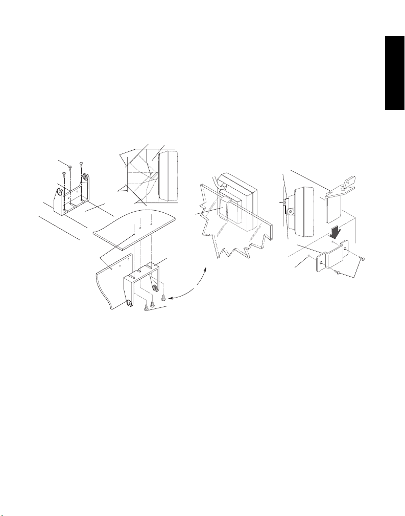
The speaker/amplifier includes a trunnion bracket, hanger bracket, and
wall mount bracket. These brackets enable the speaker to be mounted in
a variety of different ways. Refer to Figure 1.
The trunnion bracket provides a large variety of permanent mountings
(dashboard and accessible firewall areas) for the speaker, while permitting
it to be tilted or angled for best results.
Vehicles Equipped With Airbags - An airbag inflates with great
force. DO NOT place objects, including communication
equipment in the area over the airbag or in the airbag
deployment area. If the communication equipment is improperly
placed and the airbag inflates, this could cause serious injury.
Always mount the speaker securely with the supplied mounting
hardware. A speaker that is not mounted in a fixed position
could interfere with proper vehicle operation.
The mounting screws can damage cables and wires that run
under some mounting surfaces in the vehicle. Be careful to
avoid mounting the bracket above those locations.
If mounted on an insecure or hollow mounting surface, the
bracket could loosen and the unit could break free on collision.
Mount the bracket only in a location which allows self tapping
screws to solidly anchor into a metal surface.
!
WARNING
6871239M01_En.fm Page 1 Friday, February 2, 2007 5:20 PM

2
English
The hanger bracket (already attached to the speaker) by itself permits
temporary mounting on projections, such as automobile windows. In this
case, the speaker must be removed from its trunnion bracket by loosening
the two wing screws.
The wall mount bracket can be used for permanent mountings if the
trunnion bracket is too large to fit in inaccessible areas. In this case,
remove the trunnion bracket and attach the speaker to the wall mount
bracket using the hanger bracket. Security screws are included for optional
use in place of wing screws.
2. Installation
These tools are required for installation:
• Center punch
•Hammer
• Drill, 1/4" Chuck
• #22 Twist Drill (0.157") for self-tapping screws
• #38 Twist Drill (0.101") for self-tapping screws
• Nut Driver, 1/4"
• Nut Driver, 5/16"
Trunnion Bracket Installation Procedure (Refer to Figure 1.)
Step 1. Remove the trunnion bracket by loosening the two wing screws.
Step 2. Remove the three paper retainers and screws from the trunnion
bracket.
Step 3. Remove the wall mount bracket from its taped position on the
hanger bracket, and retain for future use.
Step 4. Using the trunnion bracket as a template, mark the location of the
three desired mounting holes.
6871239M01_En.fm Page 2 Friday, February 2, 2007 5:20 PM

3
English
Step 5. Centerpunch and drill a 0.157" diameter hole at each location.
Step 6. Mount the trunnion bracket using the supplied screws.
Step 7. Remount the speaker into the trunnion bracket and retighten the
two wing screws.
Wall Mount Bracket Installation Procedure (Refer to Figure 1.)
Figure 1. Physical Installation Details
Step 1. Remove the wall mount bracket from its taped position on the
hanger bracket.
Step 2. Remove the trunnion bracket and trunnion wing screws, and
retain for future use.
Step 3. Remove the two paper retainers and screws from the wall mount
bracket.
Step 4. Determine the location for the installation.
0.101'' (2.56mm)
Diameter
6-20 x 1/2''
Self-Tapping
Screw
Wall Mounting
Bracket Detail
Wall Mounting
Bracket
NOTE:
The rear cover of the speaker and the
circuit board must be temporarily
removed to mount the hanger bracket.
Hanger
Bracket
Hanger
Bracket
Vehicle
Window
Window Mounting
Detail
Trunnion Bracket
Mounting Detail
Dashboard
Firewall
Trunnion Bracket
To
Firewall
Mounting
or
Dashboard
Firewall
10-16 x 5/8''
Self-Tapping
Screw
0.157'' (3.99mm)
Diameter
Trunnion
Bracket
10-16 x 5/8''
Self-Tapping
Screw
Console or Floor
MAEPF-26870-O
6871239M01_En.fm Page 3 Friday, February 2, 2007 5:20 PM

4
English
Step 5. Using the bracket as a template, mark the location for the screws.
Step 6. Centerpunch and drill a 0.101" diameter hole at both locations.
Step 7. Mount the wall mount bracket to the surface with the supplied
screws.
Step 8. Firmly seat the hanger bracket (attached to the speaker) in the
wall mount bracket.
Dual Trunnion and Wall Mount Installation
In some installations, such as in school buses, where the speaker may be
subject to excessive strain or abuse, it may be desirable to use both the
trunnion mounting bracket and the wall mounting bracket. In this case,
follow the procedures in both 2.2 and 2.3, but use the dimensions in
Figure 2 to locate the hole centers.
Figure 2. Dual Trunnion
and Wall Mount Dimensions
NOTE: Do not use Figure 2 as a template to drill holes for mounting. It is
only to be used as a reference to show the relevant measurements.
1.92"(48.77mm)
0.96"(24.38mm)
2.31"(58.67mm)
1.155"(29.34mm)
2.56"(65.02mm)
0.375"(9.53mm)
Trunnion Bracket
Wall Mounting Bracket
MAEPF-26871-O
6871239M01_En.fm Page 4 Friday, February 2, 2007 5:20 PM

5
English
Electrical Connections
Step 1. Route wires through connector as shown in Figure 3a, or for
applications with multiple accessories connected to the mobile
radio, route wires as shown in Figure 3b and use the cable tie to
secure wires to the connector.
Step 2.Insert the contacts into pin locations #12 or #16 for black wire, pin
#7 for red wire, and pin #13 for microphone audio or pin #15 for
microphone plus receive audio for blue wire on the accessory
connector as shown in Figure 4.
Step 3.Plug the accessory connector into the back of the mobile radio.
Figure 3a. Wire Strain Relief
Figure 3b. Optional Strain Relief
Optional strain relief
with tie wrap
6871239M01_En.fm Page 5 Friday, February 2, 2007 5:20 PM

6
English
3. Adjustment
General Procedure
See the Vehicle Adapter, or mobile radio installation manual for product-
specific procedure.
Step 1. Adjust the radio as described in the radio instruction manual.
Step 2. Setup the conditions required to provide a signal to the speaker,
such as an incoming received message and set the vehicular
adapter volume level to maximum.
pin #13
pin #12
pin #7
Connector Pinout Mapping Viewed from Rear of Connector
Locking lance up on top row
Locking lance down
for bottom row
Figure 4. Terminal Orientation
pin #16
pin #15
6871239M01_En.fm Page 6 Friday, February 2, 2007 5:20 PM

7
English
Step 3. Adjust the speaker/amplifier volume control (on the speaker
circuit board) for a convenient listening level heard clearly
throughout the vehicle. The adjustment can also be used to lower
minimum loudness if the installation requires it.
4. Schematics
NTN9277A Speaker Board Detail
A+
AUD_IN
AUD_OUT
VIEWED FROM TOP SIDE
BLK_WHT
C1
C2
C3
C4
C5
C6
C7
C8
C9
C10
C12
C14
C15
GND
R1
1
2
3
R2
R3
R4R5
R6
R7
SHEILD
SPKR
SPKR_BLK_WHT
5
4
3
1
2
U1
MAEPF-26869-O
6871239M01_En.fm Page 7 Friday, February 2, 2007 5:20 PM

8
English
Speaker/Amplifier Specifications
Speaker/Amplifier Model Complement
Speaker Adjustment
Rated Voltage: +13.8 Vdc; negative ground
Audio Input: 2400 ohms with adjustable input level
Input sensitivity: 0.5 volt input for full output
Audio output to speaker: 6 watts; less than 10% distortion @ rated voltage
Frequency response: +1, -3 dB; 300-3000 Hz
Speaker: 5" permanent magnet; 2 ohms
Battery drain: Standby: less than 0.1 amp; Full output: 0.75
amp
NTN9277A Speaker/amplifier board
RLN6257A Speaker and cable
RKN4135A Interconnect cable
ADJUST SPEAKER
When the speaker is installed to XTVA (NLD7654),
it is recommended that the loudness adjustment be
set as depicted above for best receive audio clarity.
6871239M01_En.fm Page 8 Friday, February 2, 2007 5:20 PM

9
English
NTN9277A Speaker Board Schematic
1
R6
220uF
C5
0.1uF
1000pF
C4
C10
R5
C15
220pF
R4
2.2
100uF
220
C3
.047uF
C2
47
R3
0.22uF
C6
0.1uF
C7
C9
220pF
C14
220pF
C8
.01uF
C1
10uF
500
R2
1
3
3
1
6
5
4
2
2
C12
.01uF
560
R7
2.2K
R1
3
GND
2INV
1NINV
4
OUT
5
SUP_VOLT
BLK_WHT
TDA2003
U1
SPKR
SPKR_BLK_WHT
GND
AUD_OUT
AUD_IN
SHEILD
BLK-WHT
BLK LS1
2 OHM
A+
BLUE
SHIELD
BLK
RED
BLK/WHT
WHT
AUD IN
SHIELD
GND
A+
SPKR
AUD OUT
P1 CONNECTOR
SHORT CABLE
PCB
EDGE
CONNECTIONS
SPKR
63B81078C99-O
6871239M01_En.fm Page 9 Friday, February 2, 2007 5:20 PM

1
Español
Latinoamericano
1. Descripción
El parlante/amplificador está conformado por un amplificador de circuito
integrado de 6 vatios y un parlante de 2.0 ohmios, dentro de un robusto
gabinete resistente a la intemperie. El gabinete ha sido diseñado para ser
instalado en el interior o el exterior (consulte el Detalle de soporte para
montaje en ventanas, Figura 1) de un autobús escolar, un camión, un
vehículo para emergencias u otro vehículo similar.
El parlante/amplificador se utiliza como elemento opcional para los
productos Motorola XTVA, adaptadores para vehículos y otros productos
similares.
El parlante/amplificador incluye un soporte giratorio, un soporte colgante
y un soporte para montaje en paredes. Estos soportes permiten instalar el
parlante de diferentes formas. Consulte la Figura 1.
Vehículos equipados con bolsas de aire: las bolsas de aire se
inflan con gran fuerza. NO coloque objetos, incluyendo equipos
de comunicación, en el área que se encuentra encima de la
bolsa de aire ni en el área de despliegue de la bolsa de aire. Si
el equipo de comunicación se coloca incorrectamente y la bolsa
de aire se infla, puede provocar lesiones graves.
Monte siempre el parlante con firmeza con los elementos de
montaje provistos. Si el parlante no se monta en una posición
fija, puede interferir con la correcta operación del vehículo.
Los tornillos de montaje pueden dañar los cables que pasan por
debajo de la superficie de montaje del vehículo. Tenga cuidado
de evitar montar el soporte sobre esos lugares.
Si lo monta sobre una superficie inestable o hueca, el soporte
se puede aflojar y la unidad puede liberarse en caso de choque.
Monte el soporte únicamente en una ubicación que permita un
excelente agarre de los tornillos a la superficie metálica.
A
DVERTENCIA
!
Precaución
Precaución
Precaución
6871239M01_es-la.fm Page 1 Thursday, April 19, 2007 11:40 AM

2
Español
Latinoamericano
El soporte giratorio permite instalar el parlante en una amplia variedad de
montajes permanentes (tablero y áreas accesibles de la mampara
cortafuegos), además de que permite inclinarlo o colocarlo en diferentes
ángulos para obtener los mejores resultados.
El soporte colgante (ya conectado al parlante) permite instalarlo en forma
temporal sobre salientes, como las ventanas de un automóvil. En este
caso, debe retirar el parlante de su soporte giratorio aflojando los dos
tornillos de mariposa.
El soporte para montaje en paredes se puede utilizar para instalaciones
permanentes si el soporte giratorio es demasiado grande como para
colocarlo en zonas inaccesibles. En este caso, quite el soporte giratorio y
coloque el soporte para montaje en paredes en el parlante utilizando el
soporte colgante. Se entregan tornillos de seguridad que se pueden
utilizar en lugar de los tornillos de mariposa.
2. Instalación
Necesitará las siguientes herramientas para llevar a cabo la instalación:
• Punzón
• Martillo
• Taladro, portabroca de 1/4 pulg.
• Broca helicoidal Núm. 22 (0,157 pulg.) para tornillos autorroscantes
• Broca helicoidal Núm. 38 (0,101 pulg.) para tornillos autorroscantes
• Llave tubo, 1/4 pulg.
• Llave tubo, 5/16 pulg.
Procedimiento de instalación del soporte giratorio (Consulte
la Figura 1)
Paso 1. Quite el soporte giratorio desajustando los dos tornillos de
mariposa.
Paso 2. Quite los tres topes de papel y los tornillos del soporte giratorio.
Paso 3. Quite el soporte para montaje en paredes del soporte colgante
y consérvelo para utilizarlo más adelante.
6871239M01_es-la.fm Page 2 Thursday, April 19, 2007 11:40 AM

3
Español
Latinoamericano
Paso 4. Utilice el soporte giratorio como plantilla para marcar la
ubicación deseada de los tres orificios de montaje.
Paso 5. Perfore un orificio de 0,157 pulg. de diámetro en cada una de
las marcas que hizo.
Paso 6. Monte el soporte giratorio utilizando los tornillos que recibió con
el equipo.
Paso 7. Vuelva a colocar el parlante en el soporte giratorio y ajuste
nuevamente los dos tornillos de mariposa.
Procedimiento de instalación del soporte para montaje en
paredes (Consulte la Figura 1)
Figura 1. Detalles de la instalación física
Paso 1. Quite el soporte para montaje en paredes del soporte colgante.
Paso 2. Quite el soporte giratorio y los tornillos de mariposa, y
consérvelos para utilizarlos más adelante.
Paso 3. Quite los dos topes de papel y los tornillos del soporte para
montaje en paredes.
Paso 4. Determine el lugar donde se instalará el equipo.
Paso 5. Utilice el soporte a modo de plantilla y marque la ubicación de
los tornillos.
MAEPF-26870-O
Tornillo autorroscante
10-16 x 5/8”
Tornillo autorroscante
10-16 x 5/8”
Tornillo autorroscante
6-20 x 1/2”
Tab le ro
Tab le ro
Cortafuegos
Cortafuegos
Consola o piso
Soporte
giratorio
Soporte giratorio
Soporte
colgante
Soporte
colgante
Diámetro de 0,157 pulg.
(3.99mm)
Diámetro de 0,101 pulg.
(2.56mm)
A montaje en
cortafuegos
Detalle del montaje
con soporte giratorio
Detalle del montaje
en la ventana Detalle del soporte
para montaje en paredes
Soporte para montaje
en paredes
o
Ventana
del vehículo
NOTA:
Es necesario retirar temporalmente la cubierta posterior
del parlante y el tablero de circuitos para instalar
el soporte colgante.
6871239M01_es-la.fm Page 3 Thursday, April 19, 2007 11:40 AM

4
Español
Latinoamericano
Paso 6. Perfore un orificio de 0,101 pulg. de diámetro en cada una de
las marcas que hizo.
Paso 7. Monte el soporte para paredes sobre la superficie utilizando los
tornillos que recibió con el equipo.
Paso 8. Coloque firmemente el soporte colgante (conectado al parlante)
en el soporte para montaje en paredes.
Instalación combinada del soporte para paredes y el soporte
giratorio
En algunas instalaciones, como las que se realizan en autobuses
escolares, en las cuales el parlante puede recibir malos tratos o un uso
intensivo, es aconsejable utilizar tanto el soporte giratorio como el soporte
para montaje en paredes. Si éste es el caso, siga los procedimientos de
las secciones 2.2 y 2.3, pero utilice las dimensiones que se incluyen en la
Figura 2 para ubicar los centros de los orificios.
Figura 2. Dimensiones para el soporte
para paredes y el soporte giratorio combinados
NOTA: No utilice la Figura 2 como plantilla para realizar los orificios para
el montaje. Sólo se debe utilizar a modo de referencia para mostrar
las medidas correctas.
1,92"(48,77mm)
0,96"(24,38mm)
2,31"(58,67mm)
1,155"(29,34mm)
2,56"(65,02mm)
0,375"(9,53mm)
MAEPF-26871-O
Soporte para montaje
en paredes
Soporte giratorio
6871239M01_es-la.fm Page 4 Thursday, April 19, 2007 11:40 AM

5
Español
Latinoamericano
Conexiones eléctricas
Paso 1. Pase los cables a través del conector, tal como se indica en la
Figura 3a, o en el caso de aplicaciones con varios accesorios
conectados a la radio móvil, pase los cables como se indica en
la Figura 3b y utilice el precinto para sujetar los cables al
conector.
Paso 2. Inserte los contactos tal como se indica en la Figura 4: pines 12
ó 16 para el cable negro, pin 7 para el cable rojo y pin 13 para el
audio del micrófono o pin 15 para el micrófono y recepción de
audio para el cable azul en el accesorio de conexión.
Figura 3a. Elemento para aliviar tensiones del cable
Figura 3b. Elemento opcional para aliviar tensiones
Elemento para aliviar tensiones,
opcional con precinto
6871239M01_es-la.fm Page 5 Thursday, April 19, 2007 11:40 AM

6
Español
Latinoamericano
Paso 3. Conecte el conector de accesorios a la parte posterior de la
radio móvil.
3. Ajuste
Procedimiento general
Consulte el manual de instalación de la radio móvil o del Adaptador para
vehículos para conocer el procedimiento específico para su producto.
Paso 1. Ajuste la radio tal como se describe en el manual de
instrucciones.
Paso 2. Realice los ajustes necesarios para enviar una señal al
parlante, tal como un mensaje entrante recibido, y ajuste el
nivel del adaptador para vehículos al máximo.
pin núm. 13
pin núm. 12
pin núm. 7
Asignación de los pines del conector visto desde la parte posterior
Conexión en la hilera superior
Conexión en la
hilera inferior
pin núm. 16
pin núm. 15
Figura 4. Orientación del terminal
6871239M01_es-la.fm Page 6 Thursday, April 19, 2007 11:40 AM

7
Español
Latinoamericano
Paso 3. Ajuste el control de volumen del parlante/amplificador (en el
tablero de circuitos del parlante) a un nivel adecuado que se
pueda escuchar claramente en todo el vehículo. Si la
instalación lo requiere, también es posible utilizar el ajuste para
reducir el nivel mínimo de volumen.
4. Diagrama
Detalle del tablero del parlante NTN9277A
A+
AUD_IN
AUD_OUT
BLK_WHT
C1
C2
C3
C4
C5
C6
C7
C8
C9
C10
C12
C14
C15
GND
R1
1
2
3
R2
R3
R4R5
R6
R7
SHEILD
SPKR
SPKR_BLK_WHT
5
4
3
1
2
U1
VISTO DESDE ARRIBA
MAEPF-26869-O
6871239M01_es-la.fm Page 7 Thursday, April 19, 2007 11:40 AM

8
Español
Latinoamericano
Especificaciones del parlante/amplificador
Complemento del modelo parlante/amplificador
Ajuste del parlante
Tensión nominal: +13,8 VCC; tierra negativo
Entrada de audio: 2400 ohmios con nivel de entrada ajustable
Sensibilidad de entrada: entrada de 0,5 voltios para potencia máxima
Salida de audio al
parlante:
6 vatios; menos de 10% de distorsión a la
tensión nominal
Respuesta de frecuencia: +1, -3 dB; 300-3000 Hz
Parlante: imán permanente de 5 pulg; 2 ohmios
Purga de batería: En espera: menos de 0,1 amp; Potencia máxima:
0,75 amp
NTN9277A Circuito de parlante/amplificador
RLN6257A Parlante y cable
RKN4135A Cable de interconexión
AJUSTE DEL PARLANTE
Cuando se instale el parlante para XTVA (NLD7654),
se recomienda realizar el ajuste de volumen como
se indica más arriba para lograr la mayor claridad
de recepción de audio.
6871239M01_es-la.fm Page 8 Thursday, April 19, 2007 11:40 AM

9
Español
Latinoamericano
Diagrama del tablero del parlante NTN9277A
1
R6
220uF
C5
0.1uF
1000pF
C4
C10
R5
C15
220pF
R4
2.2
100uF
220
C3
.047uF
C2
47
R3
0.22uF
C6
0.1uF
C7
C9
220pF
C14
220pF
C8
.01uF
C1
10uF
500
R2
1
3
3
1
6
5
4
2
2
C12
.01uF
560
R7
2.2K
R1
3
GND
2INV
1NINV
4
OUT
5
SUP_VOLT
BLK_WHT
TDA2003
U1
SPKR
SPKR_BLK_WHT
GND
AUD_OUT
AUD_IN
SHEILD
BLK-WHT
BLK LS1
2 OHM
A+
BLUE
SHIELD
BLK
RED
BLK/WHT
WHT
AUD IN
SHIELD
GND
A+
SPKR
AUD OUT
SPKR
CONECTOR P1
CABLE CORTO
CONEXIONES
DEL TABLERO
DE CIRCUITOS IMPRESO
63B81078C99-O
6871239M01_es-la.fm Page 9 Thursday, April 19, 2007 11:40 AM
Table of contents
Languages:
Other Motorola Speakers System manuals

Motorola
Motorola MOTOROKR 6803578F35 User manual

Motorola
Motorola MT100-5-SB20 User manual

Motorola
Motorola MT160DSB User manual

Motorola
Motorola MT200-SB51 User manual

Motorola
Motorola MOTOROKR EQ7 User manual

Motorola
Motorola MBP162CONNECT User manual

Motorola
Motorola 89243N - EQ7 Wireless Hi-Fi Stereo Speaker Portable... User manual

Motorola
Motorola amphisoundX MT250-ASB31 User manual

Motorola
Motorola MT120-SB21 User manual

Motorola
Motorola MT120-5-DSB21 User manual