Motorola APX 8000XE Use and care manual

COMMUNICATIONS MANUAL
CHAPTER 11
July 17, 2019
UTILIZATION OF COMPANY HANDIE-TALKIE
TABLE OF CONTENTS
1. INTRODUCTION ..............................................................................................................1
2. DESCRIPTION AND USE OF HANDIE-TALKIE...............................................................2
3. SPECIAL FEATURES ......................................................................................................12
4. EQUIPMENT DISTRIBUTION AND ASSIGNMENTS..............................................20
5. MAINTENANCE OF PORTABLE RADIOS................................................................20
6. MISSING, LOST OR STOLEN PORTABLE RADIOS................................................22
7. RADIO FREQUENCY (RF) CHALLENGES, INTERFERENCE AND DEADSPOTS..........22
ADDENDA
1 HT Batteries and Chargers
2 Fire Dispatch Backup Zone
3 Encryption - Tactical/Dispatch Channels
4 Spare Radio Procedures
5 Setting Clock/Time of Day
6 Color Coded Radios APX8000XE

COMMUNICATIONS MANUAL
July 17, 2019 CHAPTER 11
11-1
1. INTRODUCTION
After many years of use in the FDNY, the XTS3500 has reached its end of service life.
Following an exhaustive evaluation process, a new radio with many additional features
has been selected by the FDNY.
1.1 Portable Radios: (HT)
The Department has purchased the Motorola APX8000XE radio. This multi-band radio
will provide access to every mode of voice radio communications currently used by the
FDNY. The APX8000XE portable radio can communicate on VHF, UHF & 700/800
MHz. The multi-band capability greatly enhances the department’s efficiency, increases
intra and interoperability and overall safety of our members. This UL approved,
non-incendive radio is being issued to both Fire and EMS.
1.2 New Features
1.2.1 Voice Annunciation: Announces zone and channel when powering up and
changing channels.
1.2.2 Multi-Screen View: Top display and Main display for navigation of features.
1.2.3 Recent/Mayday Retention: Will hold the IDs of the last 15 transmissions.
1.2.4 Multi-Zone Capabilities: Enhanced communication capabilities by providing
access to numerous channels.
1.2.5 Multi-Band Radio: Ability to communicate on VHF, UHF and 700/800 MHz.
1.2.6 High Visibility LED on Remote Speaker Mic (RSM): Operates on EAB
activation and manually.
1.2.7 Alpha-Numeric ID: Identification of transmitting members. i.e.: LAD 12-OV,
ENG 3-NOZ
1.2.8 Encryption: Enables secure transmissions on selected channels.

COMMUNICATIONS MANUAL
July 17, 2019 CHAPTER 11
11-2
2. DESCRIPTION AND USE OF HT
2.1 Motorola APX8000XE comes equipped with the following:
2 Watt and 5 Watt output
7" multi-band antenna
Lithium-ion rechargeable battery
Carrying case with an adjustable shoulder strap
Remote Speaker Mic (RSM)
Figure 1

COMMUNICATIONS MANUAL
July 17, 2019 CHAPTER 11
11-3
2.2 Two Displays
2.2.1 Main Display Fig 2
2.2.2 Main Display Features (Fig. 2)
Full color display, 4 lines of text up to 14 characters per line.
A. Clock/Time of Day: Is only the time set on that HT and may not be accurate.
(See Add. 6) Time of day is located in upper left-hand corner.
B. Signal: Indicates whether radio is Transmitting ,Receiving or signal
strength for Trunking
C. Direct/Simplex Channel: An indicates a direct/point to point channel.
No symbol (blank) indicates a Trunked/Repeated Channel.
D. TX Power: An Hor Lon the display indicates high (5 Watt) and low
(2 Watt) power level.
E. Battery Gauge: Indicates level of battery. Battery indicator is located in the
upper right corner of the display.
F. Zone: Indicates Zone member’s HT is set to.
G. Channel: Indicates channel member’s HT is set to.
H. Alpha-numeric Identification: By position i.e. LAD 99-Roof
Every portable radio has an assigned Internal Identification Code that is
assigned to a specific unit and riding position. The assigned internal ID will
be displaced when Radio is receiving IDs, Emergency Alerts or has a low
battery. If an alphanumeric ID does not appear, then the numeric ID will be
displayed. (See Addendum 4)

COMMUNICATIONS MANUAL
July 17, 2019 CHAPTER 11
11-4
2.2.3 Front Controls Fig 3
A. Mic is located to the left above the main display.
B. Menu/Select buttons
Single Dot: Zone - Enables changing zones.
Double Dot: Rcnt - (Recent) allows access to list of last 15 IDs received.
Triple Dot: Clck - (Clock) Allows access to internal clock application, to
reset time.
C. 4 Way Navigation Button: Allows navigation through different features on HT.
D. Home Button: Pressing and holding the Home button for long press
(2 seconds) returns the radio to the Tactical Zone A, HT channel 1.
(Note: No matter what channel the channel selector is on, you return to
Channel 1). If you wish to use a different channel, use channel selector knob.

COMMUNICATIONS MANUAL
July 17, 2019 CHAPTER 11
11-5
2.2.4 Top Display Fig 4

COMMUNICATIONS MANUAL
July 17, 2019 CHAPTER 11
11-6
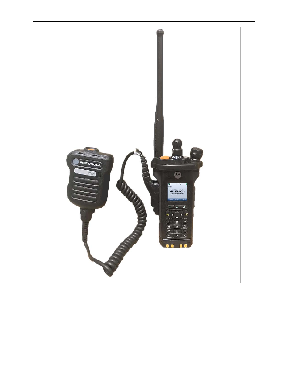
2.2.5 Top Controls Fig 5
A. ON/OFF Volume Control Knob:
Radio ON: Rotate knob clockwise until a click is heard or felt. The radio will
go through a power-up self-test.
If the power-up test is successful, a splash screen will appear on the radio
display followed by the Home screen returning to last channel and zone
selected when radio was on. The radio will return to the last channel that it
was set to when it was powered off, no matter what position the channel
selector knob is on. If the radio power-up test is unsuccessful an Error
message will appear. Turn the radio off, check the battery, and turn the radio
back on. If the radio still does not pass its self-test, it is defective. Follow
procedure in Addendum 4 for placing radio OOS.
The Portable radio must be turned ON prior to donning the bunker coat.
Volume must be adjusted for effective communications. The portable radio
must be worn under the bunker coat to reduce damage and protect the unit
from adverse weather conditions.
B. 3 Position Switch (A/B/C Zone Select):
Is used to toggle between Zone A, Zone B or Zone C. This also provides an
easy method to return to tactical zone from any zone on the radio. Move
A/B/C switch to any zone other than A and then return to A, and radio will
return to Tactical zone.
C. 16 Position Channel Selector Knob: Used to select channel in selected Zone.
D. Emergency Alert Button (EAB):
The Emergency Alert Button (EAB) adjacent to the base of the antenna is
used to activate the Emergency Alert.

COMMUNICATIONS MANUAL
July 17, 2019 CHAPTER 11
11-7
E. Transmit/Receive LED: Illuminates red light when transmitting and amber
when receiving.
Solid Red - HT is transmitting.
Blinking Red (while transmitting) - HT transmitting at low battery condition.
Blinking Red (while not transmitting) - HT is in Emergency Mode.
Solid Amber - Receiving transmission.
Blinking Amber - HT is receiving a secured transmission.
F. Top Display: See Fig 4
G. 2 Position Concentric Switch: Used to activate encryption on designated
channels.

COMMUNICATIONS MANUAL
July 17, 2019 CHAPTER 11
11-8
2.3 Side Buttons Fig 6
A. Squelch Button: (Purple)
Depressing the squelch button momentarily opens the internal squelch of the
radio for the duration of button actuation.
B. Push To Talk (PTT) Button:
Allows radio transmissions.
C. Side Button 1: (Single Square) has two modes.
Short press (Momentary) - Illuminates both main and top displays for 20
seconds.
Long Press (2 seconds) - Reverses orientation of top display.
D. Side button 2: (Double Square)
Depressing this button announces the Zone and Channel the radio is operating
on and illuminates both displays.

COMMUNICATIONS MANUAL
July 17, 2019 CHAPTER 11
11-9
2.4 Zone Selection:
The HT is provided with various zones. Each zone is a grouping of 16 channels.
To change zones, the following steps provide easy access to any channel/zone desired:
Fig 7
Note: The additional channels, zones and frequencies are an enhancement to FDNY
communications. These additional channels afford broader communication capabilities at
the Company level, as well as provide enhanced situational awareness.

COMMUNICATIONS MANUAL
July 17, 2019 CHAPTER 11
11-10
2.5 XE500 Remote Speaker Mic (RSM)
Fig 8
Fig 9

COMMUNICATIONS MANUAL
July 17, 2019 CHAPTER 11
11-11
A. Emergency Alert Button (EAB): Emergency alert button is used to activate
emergency alert and has protective ring to reduce inadvertent Emergency alert
activations.
B. LED light on top is transmit/receive indicator:
Solid Red - HT is transmitting.
Blinking Red (while transmitting) - HT transmitting at low battery condition.
Blinking Red (while not transmitting) - HT is in Emergency Mode.
Solid Amber - Receiving transmission.
Blinking Amber - HT is receiving a secured transmission.
C. Push-To-Talk (PTT) Button: The Remote Speaker Mic (RSM) includes a
recessed PTT button located on the side.
Depressing the PTT button puts HT in the Transmit Mode - When the PTT
button is depressed member should pause ½ second, allowing HT ID to be
transmitted. When the PTT button is released at the end of a transmission, a
tone will be heard through the microphone speaker. The tone level is
proportional to the volume setting.
D. Channel Annunciation Button: Depressing the button beneath the PTT button
will announce the current selected channel.
E. Mics: The RSM has 5 mics - 4 on the front and 1 on the back.
F. High Visibility LED: A high visibility LED light is mounted in the front of the
RSM for a visual indicator when the EA button is depressed. This LED light
can also be used as a flashlight by depressing the light for 2 seconds. To turn
off the light, depress the light for 2 seconds. The High Visibility LED
illuminates 18.5 lumens at 120 degrees.
Fig 10

COMMUNICATIONS MANUAL
July 17, 2019 CHAPTER 11
11-12
3. SPECIAL FEATURES
3.1 Water Resistance
The radio and the RSM are designed to be water resistant. Water resistance is highly
dependent on proper use/connection and condition of the radio seal elements. Therefore,
the radio should not be subject to unwarranted or casual submersion outside the function
of firefighting or routine maintenance. (If radio becomes submerged, refer to Sec. 5 for
proper maintenance).
3.2 Audible Tone at End of Transmission (a.k.a. Voice End Tone)
At the end of each transmission, the radio emits an audible tone to:
1) Inform the operator of the volume setting.
2) Indicate that the radio is functioning properly.
3) Signal the end of the transmission.
3.3 30 Second Time-Out-Timer
This feature cuts off the transmitter after 30 seconds of continuous transmission and is
especially useful to correct the "stuck-button" problem. At the RSM, the radio emits a
short audible warning tone at approximately 26 seconds and a continuous tone at
approximately 30 seconds. This indicates that the transmitter has been shut off.
The operator can re-key the PTT again if a longer transmission is required. This resets
the Time-Out-Timer.
3.4 Voice Recognition
The RSM voice recognition feature captures the member’s voice and reduces background
noise, providing for clearer transmissions in noisy environments.

COMMUNICATIONS MANUAL
July 17, 2019 CHAPTER 11
11-13
3.5 Emergency Alerts (EA):
Depressing Emergency Alert Button (EAB) until EA is activated, approximately 1 second,
will cause the following actions.
3.5.1 Emergency Alert Activation:
Activation of the EA will cause the following actions on the members HT who
depressed EAB.
Fig 11

COMMUNICATIONS MANUAL
July 17, 2019 CHAPTER 11
11-14
3.5.1.1 Audible Alerts: When EAB is depressed, Audible Alerts are emitted.
Alert Tones: Alert tones are the audio signal transmitted to other HTs
within range of the transmitting HT notifying others a member has
activated his/her EA. This signal alerts members of a Mayday or
Urgent situation. There are two types of alert tones; Impolite and
Polite. The APX8000XE transmits One (1)-Impolite and Two (2)-
Polite Alerts.
Impolite Alert - An impolite call is when the radio sends a
transmission even when the channel is busy with other radio traffic,
however it will NOT preempt any ongoing transmissions.
Note: Due to radio frequency (RF) anomalies, some radios may not
receive the emergency alert. Proximity, concrete, steel,
building construction, height, terrain and other factors can
contribute to the individual member’s radio ability to receive
the transmitting member’s EA.
Polite Alert - A polite call is when the radio sends a transmission
when the channel is not busy with other radio traffic. Thereby, increasing
the likelihood that other members will receive Emergency alert.
Approximately 8 seconds after the impolite transmission,
the Polite Alert is sent. Therefore, the Polite Alert may be
more than 8 seconds after the Impolite Alert tone if other
members are transmitting. The APX8000XE HT will
transmit 2 Polite Alerts to attempt to reach as many
members as possible.
All 3 Alerts will be transmitted, regardless if members are
transmitting or receiving messages. The Impolite Alert will
go out first, followed by 2 Polite Alerts when the channel is
clear.
Beacon Tone: Manual activation of a radio EA, will initiate an audible
Beacon transmitted from that radio. This beacon is used to locate
member that activated the EA. This audible beacon is emitted from
members HT until it is reset by member.
Reset EA: EA may be reset by depressing EAB for 2 seconds, or by
turning HT off and then back on.

COMMUNICATIONS MANUAL
July 17, 2019 CHAPTER 11
11-15
3.5.2 Emergency Alerts Received
Activation of the EA will cause the following actions on the HTs that are
receiving the EA.
Fig 12

COMMUNICATIONS MANUAL
July 17, 2019 CHAPTER 11
11-16
3.5.2.1 Transmissions received from member transmitting EA.
Emergency Call: Whenever a member who has transmitted an EA
depresses the PTT button, members receiving such a transmission will
observe Orange band with Emergency call appearing on Main display
with Unit and Position. Similar information will scroll across the top
display (Fig 12a). All transmissions from member will appear similarly
until EA is cleared.
Fig 12a

COMMUNICATIONS MANUAL
July 17, 2019 CHAPTER 11
11-17
3.5.3 Recall Emergency Alert (EA) and Recent transmissions.
The IDs of the last 15 received transmissions (Recent Calls List) can be viewed in
the following manner.
Fig 13

COMMUNICATIONS MANUAL
July 17, 2019 CHAPTER 11
11-18
3.6 Backlight:
Depressing any button will illuminate both displays for approximately 20 seconds.
3.7 Channel Annunciation:
Channel annunciation will occur automatically when radio is turned on, and any time the
zone or channel is changed. Member may confirm current channel they are on by
depressing channel annunciation button on RSM just beneath the PTT button or the
double square side button on the radio.
3.8 Batteries:
The APX 8000XE utilizes a Motorola Impres 2 lithium ion battery.
3.8.1 Removing battery:
Fig 14

COMMUNICATIONS MANUAL
July 17, 2019 CHAPTER 11
11-19
3.8.2 Replacing Battery: Fig 15
Other manuals for APX 8000XE
5
Table of contents
Other Motorola Transceiver manuals

Motorola
Motorola GP360 Series User manual

Motorola
Motorola T5ZX1 User manual

Motorola
Motorola SC 300 User manual

Motorola
Motorola MICOM-2E ALE User manual

Motorola
Motorola HF-SSB User manual

Motorola
Motorola LM2000 - SOUTHERNLINC User manual

Motorola
Motorola TETRA MTP850 EX User manual

Motorola
Motorola Micom-2 User manual

Motorola
Motorola MICOM-2ES User manual

Motorola
Motorola HF-SSB MICOM-500E-A G761AA User manual