2
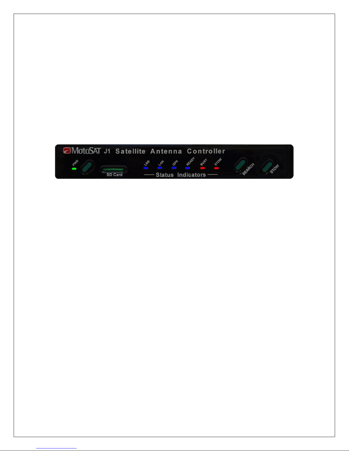
The DataStorm H3 Satellite Antenna Controller
Features
Stand Alone Satellite Antenna Controller
Front Panel Search, Stow, and Power Commands
No Software Required on PC
DVB-S2 Satellite dentification (N D)
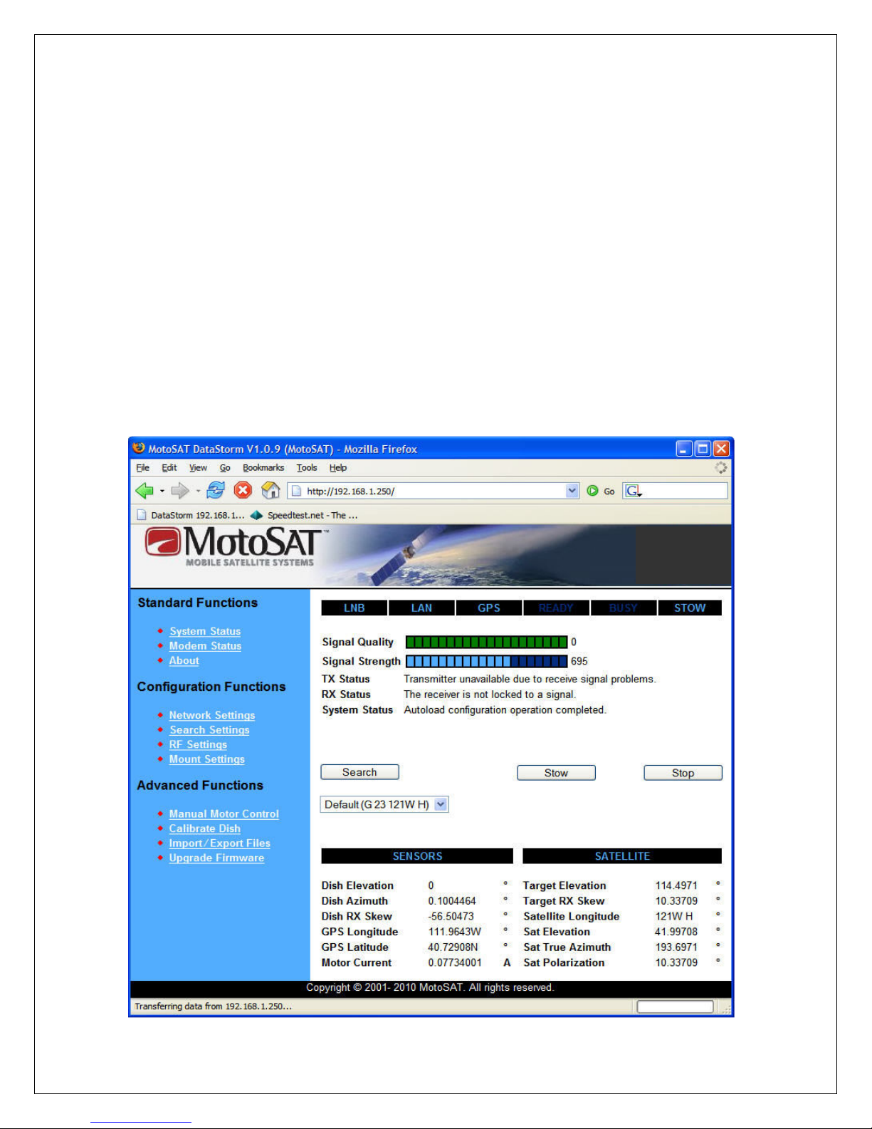
HTML Graphical User nterface
SD Card Firmware Upgrades
SD Card Configuration mports
Web Direct Sat Table mports
LED Status ndicators
Simplified Multiple Sat Select Screen
Telnet Commands for Diagnostics
mport and Export Configuration Files
mport and Export Satellite Tables
Simple Electrical Connections
HTML and Telnet Security
The DataStorm H3 Satellite Antenna Controller
The DataStorm H3 Satellite Antenna Controller is one of the most advanced Satellite Antenna
Controllers available. Simple User operation combined with many advanced configurable
features will allow the flexibility needed for almost any application anywhere.
Operate from the Front Panel or through a PC using an nternet Browser such as
nternet Explorer, Firefox, Sapphire, Chrome or many other Browsers.
No external software is required.
A true stand alone Satellite Antenna Controller now with SD Card nterface.
NOTE: The DataStorm H3 Satellite Antenna Controller can be used with
either the
• Automatic pole mount ( ESA) which stows in a “bird bath” position
or the
• obile automatic mount ( ESSENGER) which stows in a “face
down” horizontal position.
The H3 Antenna Controller is available in either a “Stand alone” or “Rack
ount” configuration.
This manual is written to use the “face down horizontal” mount as an
example and was written to reference the Stand Alone style.